manuals.online logo
Brands
  1. Home
  2. •
  3. Brands
  4. •
  5. Contec
  6. •
  7. Control Unit
  8. •
  9. Contec RRY-16CX-USB User manual

Contec RRY-16CX-USB User manual

Ver.1.00
RRY-16CX-USB 1
Digital Output Unit with Relay-Isolation
for USB
RRY-16CX-USB
* Specifications, color and design of the products are subject
to change without notice.
This product is an USB2.0-compliant digital output unit that
output signals to reed relay contacts.
This product provides up to 16 independent common reed
relay contact outputs. Independent common terminal
provided per channel, capable of supporting a different
external power supply. High-capacity output rating is
designed to be a maximum of 2A 125V (AC), 2A 30V (DC) per
channel.
As there is compatible with PCI bus-compatible board
RRY-16C(PCI)H and PCI Express bus-compatible board
RRY-16C-PE in terms of connector shape and pin
assignments, it is easy to migrate from the existing system.
Windows driver is bundled with this product. Possible to be
used as a data recording device for LabVIEW, with dedicated
libraries.
16 independent common reed relay contact outputs (with
a single make contact)
This product has 16 reed relay outputs with a single make
contact. Independent common terminal provided per channel,
capable of supporting a different external power supply.
High-capacity output rating is designed to be a maximum of 2A
125V (AC), 2A 30V (DC) per channel.
Compatible to USB1.1/USB2.0
Compatible to USB1.1/USB2.0 and capable to achieve high
speed transfer at HighSpeed (480 Mbps).
USB HUB function
This product has the USB HUB function. Max. 4
RRY-16CX-USB can be used in 1 USB port of PC. *1
When you use 4 or more RRY-16CX-USB, you can do by
connecting RRY-16CX-USB to the another USB port of PC
side. Also, you can connect the CONTEC’s USB device other
than RRY-16CX-USB to the USB port of RRY-16CX-USB.
*2*3
Connectors are compatible with PCI/PCI Express
bus-compatible board
As there is compatible with RRY-16C(PCI)H and RRY-16C-PE
in terms of connector shape and pin assignments, it is easy to
migrate from the existing system. If the system of this
product is created by the digital I/O driver API-DIO(98/PC), it is
required to replace it with API-DIO(WDM).
Windows compatible driver libraries are attached.
Using the attached digital I/O driverAPI-DIO(WDM) makes it
possible to create applications of Windows. In addition, a
diagnostic program by which the operations of hardware can
be checked is provided.
LabVIEW is supported by a plug-in of dedicated library
VI-DAQ.
Using the dedicated library VI-DAQ makes it possible to make
a LabVIEW application.
*1 This product cannot be stacked up for installation.
*2 Do not connect the device other than that of CONTEC’s USB to the USB port included
on the RRY-16CX-USB. Otherwise, this may cause a failure or malfunction.
*3 When connecting multiple units with USB HUB function and set up them, do one at a
time and complete setup for the previous unit before starting to do the next unit.
Features
USB cable
USB cable USB cable USB cable
PLUG-IN Electronic GmbH • Am Sonnenlicht 5 • 82239 Alling • Tel.: +49 (0) 8141 3697-0 • [email protected] • www.plug-in.de
Ver.1.00
RRY-16CX-USB 2
Item Specification
No. of Output Channels 16 channels (independent common)
Output Format Reed Relay (1a, make) Output
Max. rating capacity 2A 125V(AC), 2A 30V(DC) (load resister)
Max. permitted
voltage 125V (Max.) *1, *2
Max. Carry Current 2A (Max.)
Contact resistance
(Initial state) 30mΩor less
Operating time
(At the time of ON) Within 7ms
Recovery time
(At the time of OFF) Within 6ms
Mechanical Life
Expectancy 20,000,000 operations min or more Switching times :
180/min
Electrical lifetime 100,000 operations min or more Switching times :
20/min
Relay
Contact
Spec.
Relay Type PCN-105D3MHZ
USB section
Bus specification USB Specification 2.0/1.1 standard
USB transfer rate 12Mbps (Full-speed), 480Mbps (High-speed) *3
Power supply Self-power
Common section
Number of terminals used at
the same time 127 terminals (Max.) *4
Dielectric strength 250Vrms
Current consumption (Max.) 5VDC 600mA
Operating conditions*5 0 - 50ºC, 10 - 90%RH (No condensation)
Allowable distance of signal
extension Approx. 50m (depending on wiring environment)
Physical dimensions (mm) 180(W) x 140(D) x 34(H) (No protrusions)
Weight 400g (Not including the USB cable, attachment)
Connector 37-pin D-SUB, female connector
DCLC-J37SAF-20L9E(mfd. by JAE) or equivalent to it
Attached cable USB cable 1.8m
*1 Please exceed neither max. permitted voltage nor max. rating capacity of the use relay
when using it by the voltage that exceeds 30VDC. Doing so can cause a malfunction.
*2 The potential difference between channels must not exceed 125V in the maximum.
Doing so can cause a malfunction.
*3 This depends on the PC environment used (OS and USB host controller).
*4 As a USB hub is also counted as one device, you cannot just connect 127 USB unit.
*5 To suppress the heating, ensure that there are spaces for ventilation (about 5cm) around
this product.
Windows version of digital I/O driver API-DIO(WDM)
[Stored on the bundled CD-ROM driver libraryAPI-USBP(WDM)]
It is the library software, and which supplies command of
hardware produced by our company in the form of standard
Win32 API function (DLL). Using programming languages
supporting Win32API functions, such as Visual Basic and
Visual C++ etc., you can develop high-speed application
software with feature of hardware produced by our company.
In addition, you can verify the operation of hardware using
Diagnostic programs.
< Operating environment >
OS Windows 7, Server 2008, Vista, XP,
Server 2003, 2000, Me, 98
Adaptation language Visual Basic, Visual C++, Visual C#,
Delphi, C++ Builder
You can download the updated version from the CONTEC’s
Web site (http://www.contec.com/product/device/apiusbp/).
For more details on the supported OS, applicable language
and new information, please visit the CONTEC’s Web site.
Data acquisition VI library for LabVIEW VI-DAQ
(Available for downloading (free of charge) from the CONTEC web site.)
This is a VI library to use in National Instruments LabVIEW.
VI-DAQ is created with a function form similar to that of
LabVIEW's Data Acquisition VI, allowing you to use various
devices without complicated settings.
See http://www.contec.com/vidaq/ for details and download of
VI-DAQ.
Cable (Option)
Flat cable with both-ends 37-pin D-SUB connector
: CB37P-1.5 (1.5m)
: PCB37P-3 (3m)
: PCB37P-5 (5m)
Shield cable with both-ends 37-pin D-SUB connector
: PCB37PS-0.5P (0.5m)
: PCB37PS-1.5P (1.5m)
: PCB37PS-3P (3m)
: PCB37PS-5P (5m)
Flat cable with one-end 37-Pin D-SUB connector
: PCA37P-1.5 (1.5m)
: PCA37P-3 (3m)
: PCA37P-5 (5m)
Shield cable with one-end 37-pin D-SUB connector
: PCA37PS-0.5P (0.5m)
: PCA37PS-1.5P (1.5m)
: PCA37PS-3P (3m)
: PCA37PS-5P (5m)
Connector (Option)
37pin D-SUB(male) connector Five-piece set
: CN5-D37M
Accessories (Option)
Screw Terminal (M3 x 37P) : EPD-37A *1*2
Screw Terminal (M3.5 x 37P) : EPD-37 *1
General Purpose Terminal (M3 x 37P) : DTP-3A *1
Screw Terminal (M2.6 x 37P) : DTP-4A *1
USB I/O Unit Bracket for X Series : BRK-USB-X
AC adapter (input : 90 - 264VAC, output : 5VDC 2.0A)
:POA200-20-2 *3
AC-DC power supply unit(input: 85 - 132VAC, output: 5VDC 3.0A)
: POW-AC13GY
AC-DC power supply unit(input: 85 - 264VAC, output: 5VDC 2.0A)
: POW-AD22GY
DC-DC power supply unit(input: 10 - 30VDC, output: 5VDC 3.0A)
: POW-DD10GY
DC-DC power supply unit(input: 30 - 50VDC, output: 5VDC 3.0A)
: POW-DD43GY
*1 PCB37P or PCB37PS optional cable is required separately.
*2 “Spring-up” type terminal is used to prevent terminal screws from falling off.
*3 It is the same as the one appended to the product. Please buy it necessary for
maintenance.
* Check the CONTEC’s Web site for more information on these options.
- Unit [RRY-16CX-USB] …1
- AC adapter …1
- AC Cable (for 125VAC) …1
- USB cable (1.8m) …1
- USB cable attachment on the main unit’s side
(For Mini B connector side) …1
- Clamps for prevention of cable on the main unit’s side …1
- CD-ROM *1 [API-USBP(WDM)] …1
- First step guide … 1
- Power connector MC1,5/3-ST-3,5 …1
- Ferrite core …1
*1 The CD-ROM contains the driver software and User’s Guide (this guide)
Packing List
Cable & Connector
Support Software
Accessories
Specification
PLUG-IN Electronic GmbH • Am Sonnenlicht 5 • 82239 Alling • Tel.: +49 (0) 8141 3697-0 • [email protected] • www.plug-in.de
Ver.1.00
RRY-16CX-USB 3
Connecting to a Connector
To connect an external device to this product, plug the cable
from the device into the interface connector (CN1) of unit
shown below.
* Please refer to the 2 page for more information on the supported cable and accessories.
Connector Pin Assignment
Pin Assignments of Interface Connector(CN1)
CN1
Pin No. Signal
name Meaning Pin No.
Signal
name Meaning
19 N.C.
37 N.C. 18 N.C.
36 N 17
Common of O-17 17 O-17
35 N 16 Common of O-16 16 O-16
34 N 15 Common of O-15 15 O-15
33 N 14 Common of O-14 14 O-14
32 N 13 Common of O-13 13 O-13
31 N 12 Common of O-12 12 O-12
30 N 11 Common of O-11 11 O-11
29 N 10 Common of O-10 10 O-10
+1 Output Port
28 N 07
Common of O-07 9 O-07
27 N 06 Common of O-06 8 O-06
26 N 05 Common of O-05 7 O-05
25 N 04 Common of O-04 6 O-04
24 N 03 Common of O-03 5 O-03
23 N 02 Common of O-02 4 O-02
22 N 01 Common of O-01 3 O-01
21 N 00 Common of O-00 2 O-00
+0 Output Port
20 N.C. 1 N.C.
O-00 - O-17 16 output signal pins. Connect these pins to the input signal pins of the
external device.
N00 - N17 Common pin corresponding to each output pin.
N.C. No connection to this pin.
Block Diagram
Physical Dimensions
Using the Connectors
-Connector used 37-pin D-SUB connector
[F(female)type]
DCLC-J37SAF-20L9E [mfd by JAE]+
equivalence to it
Lock nut UNC #4-40 (inch screw threads)
-Compatible connector 17JE-23370-02(D8C)
[mfd by DDK, M(male)type]
FDCD-37P [mfd by HIROSE, M(male)type]
DC-37P-N [mfd by JAE, M(male)type]
Interface connector (CN1)
19
37
1
20
PLUG-IN Electronic GmbH • Am Sonnenlicht 5 • 82239 Alling • Tel.: +49 (0) 8141 3697-0 • [email protected] • www.plug-in.de
Ver.1.00
RRY-16CX-USB 4
Figures shows the output circuit at the interface section of the
board. The signal output section uses a relay contact method
to send signals to the external device.
Output Circuit
CAUTION
When the power turned on, all outputs are reset to OFF.
Example of Connection
Output a "1" to a bit will light the LED that is connected to the
related relay output. On the other hand, output a "0" to the bit
will switch the LED off.
This product must be connected with 5VDC power supply (in a
self-powered state). Connect with 5VDC power supply by
using +5VDC input pin.
When using the attached AC adapter [POA200-20-2], please
connect directly to the input terminals. When the
accompanying power connector (MC1,5/3-ST-3,5, suitable
cable: AWG28 - 16) is used to supply power to this unit, strip
the end of the suitable cable and insert it to the power
connector before firmly securing it using a screw.
CAUTION
- Connect 5VDC power supply to the main unit. Next, connect the
USB cable to the PC. Do not turn it on or off when using. If you
remove, USB cable is first and then 5VDC power supply.
- When the USB module is not used, leave the AC adapter unplugged.
- Continuously using the AC adapter heated affects its life.
- Use the AC adapter not in a closed place but in a well-ventilated
place not to be heated.
- Do not remove the power connector [MC1,5/3-ST-3,5] attached to the
AC adapter.
セルフパワー用の5VDC電源との接続 セルフパワー用の5VDC電源との接続
Item RRY-16CX-USB RRY-16C-PE RRY-16C(PCI)H
Max. rating capacity 2A 125V(AC), 2A 30V(DC) (load resister) None
Max. permitted
voltage 125V (Max.) *1, *2 125V(AC), 30V(DC)
Current
consumption (Max.) 5VDC 600mA 3.3VDC 1100mA 5VDC 550mA
Bus specification USB Specification 2.0/1.1
standard PCI Express Base
Specification Rev. 1.0a x1 PCI(32bit, 33MHz, Universal
key shapes supported)
Physical
dimensions (mm) 180(L) x 140(D) x 34(H)
(No protrusions) 121.69(L) x 110.18(H) 121.69(L) x 105.68 (H)
Weight 400g
(Not including the USB cable,
attachment)
120g
*1 Please exceed neither max. permitted voltage nor max. rating capacity of the use relay
when using it by the voltage that exceeds 30VDC. Doing so can cause a malfunction.
*2 The potential difference between channels must not exceed 125V in the maximum.
Doing so can cause a malfunction.
Output Signal Connection
Connection with 5VDC Power Supply fo
r
Sel
f
-
p
owe
r
Vi+ Power supply (5V)
Vi- Power supply (GND)
FG Frame ground
Difference from RRY-16C-PE and
RRY-16C
(
PCI
)
H
PLUG-IN Electronic GmbH • Am Sonnenlicht 5 • 82239 Alling • Tel.: +49 (0) 8141 3697-0 • [email protected] • www.plug-in.de

Other Contec Control Unit manuals

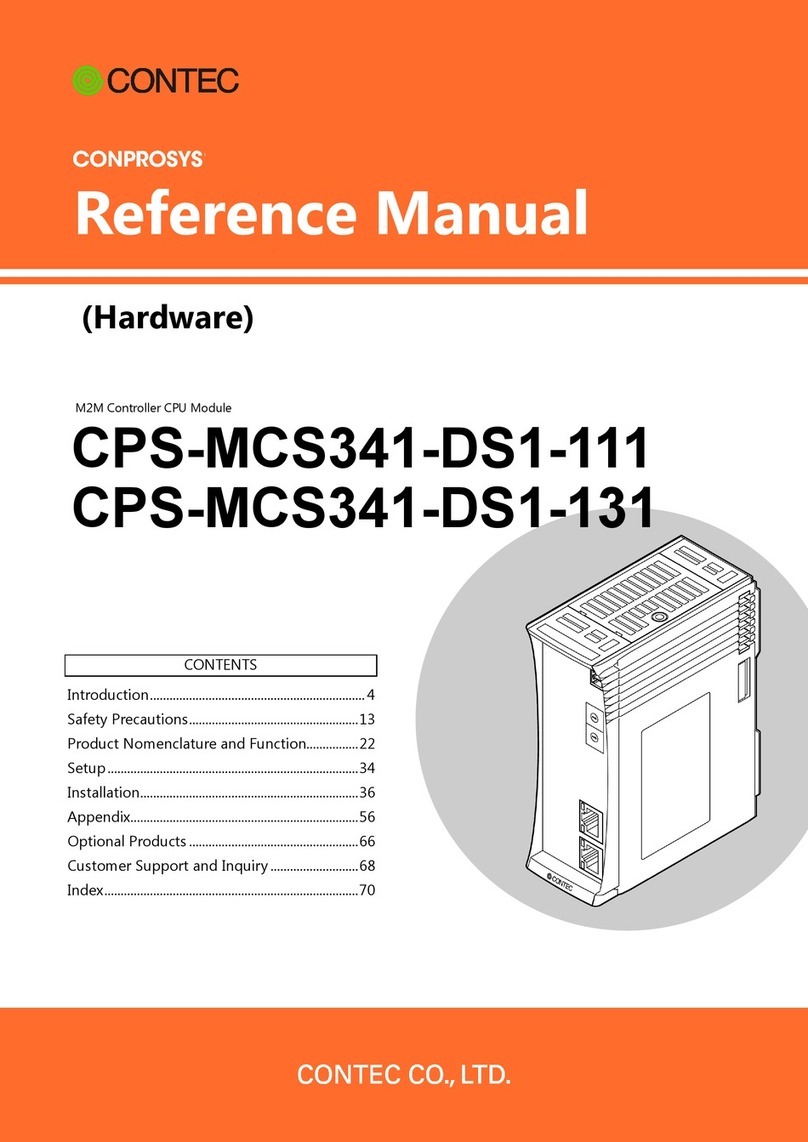
Contec CONPROSYS CPS-MCS341-DS1-111 User manual

Contec

Contec CONPROSYS CPS-MCS341-DS1-111 User manual

Contec COM-4CN-USB User manual

Contec

Contec COM-4CN-USB User manual

Contec CPSN-SSI-4C User manual

Contec

Contec CPSN-SSI-4C User manual

Contec CNT16-8GY User manual

Contec

Contec CNT16-8GY User manual

Contec CONPROSYS Series User manual

Contec

Contec CONPROSYS Series User manual

Contec PLUG-IN PTI-4GY User manual

Contec

Contec PLUG-IN PTI-4GY User manual

Contec ADI16-4(FIT)GY User manual

Contec

Contec ADI16-4(FIT)GY User manual

Contec DAI12-4GY User manual

Contec

Contec DAI12-4GY User manual

Contec CPS-AO-1604LI User manual

Contec

Contec CPS-AO-1604LI User manual

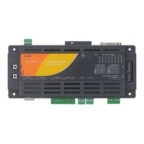
Contec Conprosys CPS-MC341-ADSC1-111 User manual

Contec

Contec Conprosys CPS-MC341-ADSC1-111 User manual

Contec AI-1608VIN-USB User manual

Contec

Contec AI-1608VIN-USB User manual

Contec F&eIT Series User manual

Contec

Contec F&eIT Series User manual

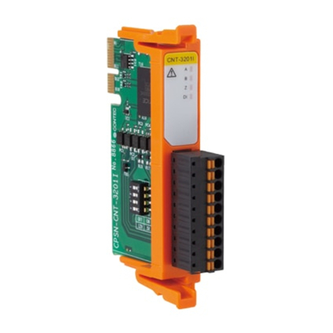
Contec CONPROSYS nano CPSN-CNT-3201I User manual

Contec

Contec CONPROSYS nano CPSN-CNT-3201I User manual

Contec CONPROSYS Series User manual

Contec

Contec CONPROSYS Series User manual

Contec F&eIT Series User manual

Contec

Contec F&eIT Series User manual

Contec CNT24-2GY User manual

Contec

Contec CNT24-2GY User manual

Contec F&eIT Series User manual

Contec

Contec F&eIT Series User manual

Contec DS540-MPCI4W User manual

Contec

Contec DS540-MPCI4W User manual

Contec CPS-DO-16L User manual

Contec

Contec CPS-DO-16L User manual

Popular Control Unit manuals by other brands

KEUCO 59948 000070 Installation and operating instructions

KEUCO

KEUCO 59948 000070 Installation and operating instructions

Paxton Switch2 quick start guide

Paxton

Paxton Switch2 quick start guide

ASAHI YUKIZAI Dymatrix AVSDV user manual

ASAHI YUKIZAI

ASAHI YUKIZAI Dymatrix AVSDV user manual

Honeywell Esser 8044 Series Installation instruction

Honeywell

Honeywell Esser 8044 Series Installation instruction

Pilz PNOZ m EF 8DI4DO operating manual

Pilz

Pilz PNOZ m EF 8DI4DO operating manual

Fanstel BluNor BT840XEE manual

Fanstel

Fanstel BluNor BT840XEE manual

Fortin EVO ALL Regular Installation

Fortin

Fortin EVO ALL Regular Installation

Vortice CR5N Instruction booklet

Vortice

Vortice CR5N Instruction booklet

LG EBR81777301 user manual

LG

LG EBR81777301 user manual

Eaton RF96APM manual

Eaton

Eaton RF96APM manual

ILX Lightwave LDC-3916558 user guide

ILX Lightwave

ILX Lightwave LDC-3916558 user guide

Atest Gaz Sigma MOD AO user manual

Atest Gaz

Atest Gaz Sigma MOD AO user manual

Rohm LAPIS Semiconductor ML22Q663 manual

Rohm

Rohm LAPIS Semiconductor ML22Q663 manual

Infineon AIROC IFW56810 Getting started

Infineon

Infineon AIROC IFW56810 Getting started

Nelson 800 Series quick start guide

Nelson

Nelson 800 Series quick start guide

Rosendahl bonsaiLAN instruction manual

Rosendahl

Rosendahl bonsaiLAN instruction manual

Newland EM2037-V4 Integration guide

Newland

Newland EM2037-V4 Integration guide

Saluki SMR Series Quick start manual

Saluki

Saluki SMR Series Quick start manual

manuals.online logo
manuals.online logoBrands
  • About & Mission
  • Contact us
  • Privacy Policy
  • Terms and Conditions

Copyright 2025 Manuals.Online. All Rights Reserved.