manuals.online logo
Brands
  1. Home
  2. •
  3. Brands
  4. •
  5. Contec
  6. •
  7. Control Unit
  8. •
  9. Contec CONPROSYS Series User manual

Contec CONPROSYS Series User manual

Ver.1.02
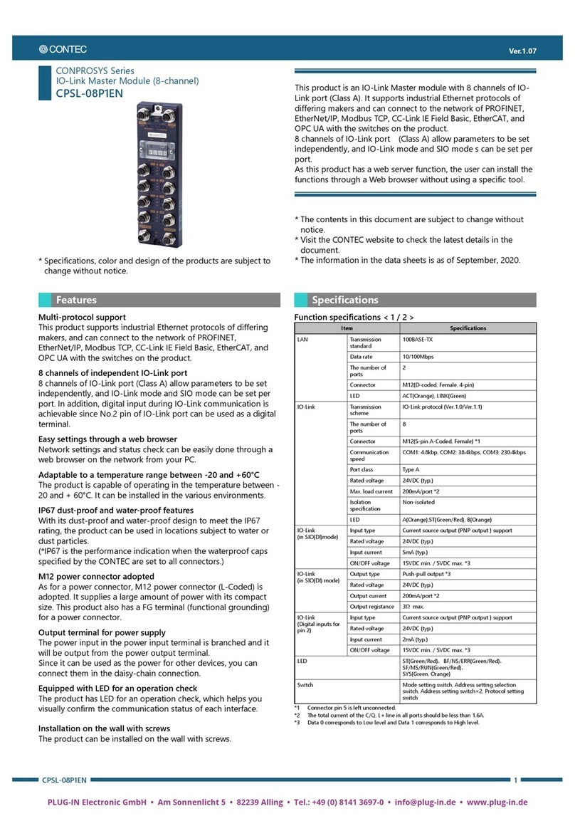
CPSL-08P1EN 1
CONPROSYS Series
IO-Link Master Module (8-channel)
CPSL-08P1EN
* Specifications, color and design of the products are subject to
change without notice.
This product is an IO-Link Master module with 8 channels of IO-
Link port (Class A). It supports industrial Ethernet protocols of
differing makers and can connect to the net-work of PROFINET,
EtherNet/IP, Modbus TCP, and CC-Link IE Field Basic with the
switches on the product.
8 channels of IO-Link port (Class A) allow parameters to be set
independently, and IO-Link mode and SIO mode s can be set per
port.
As this product has a web server function, the user can install the
functions through a Web browser without using a specific tool.
* The contents in this document are subject to change without
notice.
* Visit the CONTEC website to check the latest details in the
document.
* The information in the data sheets is as of November, 2019.
Features
Multi-protocol support
This product supports industrial Ethernet protocols of differing
makers, and can connect to the network of PROFINET,
EtherNet/IP, Modbus TCP, and CC-Link IE Field Basic with the
switches on the product.
8 channels of independent IO-Link port
8 channels of IO-Link port (Class A) allow parameters to be set
independently, and IO-Link mode and SIO mode can be set per
port. In addition, digital input during IO-Link communication is
achievable since No.2 pin of IO-Link port can be used as a digital
terminal.
Easy settings through a web browser
Network settings and status check can be easily done through a
web browser on the network from your PC.
Adaptable to a temperature range between -20 and +60°C
The product is capable of operating in the temperature between -
20 and + 60°C. It can be installed in the various environments.
IP67 dust-proof and water-proof features
With its dust-proof and water-proof design to meet the IP67
rating, the product can be used in locations subject to water or
dust particles.
(*IP67 is the performance indication when the waterproof caps
specified by the CONTEC are set to all connectors.)
M12 power connector adopted
As for a power connector, M12 power connector (L-coded) is
adopted. It supplies a large amount of power with its compact
size. This product also has a FG terminal (functional grounding)
for a power connector.
Output terminal for power supply
The power input in the power input terminal is branched and it
will be output from the power output terminal.
Since it can be used as the power for other devices, you can
connect them in the daisy-chain connection.
Equipped with LED for an operation check
The product has LED for an operation check, which helps you
visually confirm the communication status of each interface.
Installation on the wall with screws
The product can be installed on the wall with screws.
Specifications
Function specifications < 1 / 2 >
Item
Specifications
LAN
Transmission
standard
100BASE-TX
Data rate
10/100Mbps
The number of
ports
2
Connector
M12(D-coded, Female, 4-pin)
LED
ACT(Orange), LINK(Green)
IO-Link
Transmission
scheme
IO-Link protocol (Ver.1.0/Ver.1.1)
The number of
ports
8
Connector
M12(A-coded, Female, 5-pin)*1
Communication
speed
COM1: 4.8kbp, COM2: 38.4kbps, COM3: 230.4kbps
Port class
Type A
Rated voltage
24VDC (typ.)
Max. load current
200mA/port *2
Isolation
specification
Non-isolated
LED
A(Orange),ST(Green/Red), B(Orange)
IO-Link
(in SIO(DI)mode)
Input type
Current source output (PNP output ) support
Rated voltage
24VDC (typ.)
Input current
5mA (typ.)
ON/OFF voltage
15VDC min. / 5VDC max. *3
IO-Link
(in SIO(DI) mode)
Output type
Push-pull output *3
Rated voltage
24VDC (typ.)
Output current
200mA/port *2
Output registance
3Ωmax.
IO-Link
(Digital inputs for
pin 2)
Input type
Current source output (PNP output ) support
Rated voltage
24VDC (typ.)
Input current
2mA (typ.)
ON/OFF voltage
15VDC min. / 5VDC max. *3
LED
ST(Green/Red)、BF/NS/ERR(Green/Red)、
SF/MS/RUN(Green/Red)、
SYS(Green, Orange)
Switch
Mode setting switch, Address setting selection
switch, Address setting switch×2, Protocol setting
switch
*1 Connector pin 5 is left unconnected.
*2 The total current of the C/Q, L+ line in all ports should be less than 1.6A.
*3 Data 0 corresponds to Low level and Data 1 corresponds to High level.
Ver.1.02
CPSL-08P1EN 2
Function specifications < 2 / 2 >
Item
Specifications
Power input *4*5
Rate input voltage
(current)
U
S
: 24VDC (1.8A),
UA: 24VDC (0.1A)
Max. input current
US: 12A, UA: 12A
Input voltage range
US: 20.4 –26.4VDC, UA: 20.4 –26.4VDC
Device current
comsumption
U
S
: 0.2A(Max.), U
A
: 0.1A(Max.)
Connector
M12(L-coded, Male, 5(4+FE)pin)
Power output *4
Output voltage *6
U
S
: US input voltage (Max.),
UA: UA input voltage (Max.)
Max. output current *7
US: 12A, UA: 12A
Connector
M12(L-coded, female, 5(4+FE)pin)
Physical dimensions (mm)
69.0(W)×225.0(D)×18.0(H)
(No projection included)
Weight
600g
Protective function
IP67 *8
Installation method
Installation with screws *9
*4 Use power cable within 3meters.
*5 UA power is unavailable with this product. It is not necessary to supply power to UA when
you only use the device on its own.
*6 The voltage input to the power input terminal is output as it is, but if the current from the
output terminal is large, a voltage drop may occur due to the internal resistance.
*7 The total current from the power output current, device consumption current, and output
current to the IO-Link port should be supplied to the power supply input terminal.
*8 Do not use this product immersed in water.
*9 The commercial screws are required individually.
Installation Environment Requirements
Item
CPS-MM-LC
Operating ambient
temperature
-20 - +60°C
Operating ambient humidity
10 - 90%RH (No condensation)
Non-operating ambient
temperature
-20 - +60°C
Non-operating ambient
humidity
10 - 90%RH (No condensation)
Corrosive gases
None
Line-noise
resistance
Line noise
AC line/±2kV *10
Signal line/±1kV(IEC61000-4-4 Level 3, EN61000-4-4 Level 3)
Static
electricity
resistance
Touch/±4kV(IEC61000-4-2 Level 2, EN61000-4-2 Level 2)
Air/±8kV(IEC61000-4-2 Level 3, EN61000-4-2 Level 3)
Vibration
resistance
(The product
alone) *9
Sweep
resistance
10 - 57Hz *11 / semi-amplitude vibration 0.15mm, 57 -
150Hz/2.0G
40minutes each in X, Y, and Z directions (JIS C60068-2-6-
compliant, IEC60068-2-6-compliant)
Altitude
5000m or less
Shock resistance
(The product alone) *10
15G half-sine shock for 11ms in X, Y, and Z directions
(JIS C 60068-2-27 –compliant, IEC 60068-2-27 -compliant)
Grounding
Class D grounding (previous class 3 grounding)
Standard
VCCI ClassA, FCC ClassA,
CE Marking(EMC Directive Class A, RoHS Directive)
*10 When you use the CPS-PWD-90AW24-01 (optional power product)
*11 When you use an optional power product:10 - 55Hz (See the manual of optional power
product for details)
Physical Dimensions
Circuit Block Diagram
Component Name
No.
Name
Function
1
LAN Port
It is a connector for Ethernet communuication.
2
FE Terminal
It is a terminal for functional groudning.
(This hole is also used to secure the main body with a screw).
3
Status LED
Status of the product is indicated with LEDs.
4
Mode Setting Switch
It is a switch for boot mode setting.
(Do not perform any operations other than those described in
this manual.)
5
Maintenance Connector
Do not use this.
6
Address Setting Selection
Switch
It is a switch to select a setting method for the IP address of
the product.
7
Address Setting Switch
It is a switch to set an address of the product.
8
Protocol Setting Switch
It is a switch to select an Ethernet protocol.
9
IO-Link Connector
It is an IO-Link communication connector.
10
Screw Mounting Hole
It is a hole to fix and secure the main body with a screw.
11
Power Input Connector
It is a connector to supply power.
12
Power Output Connector
It is a connector to send power to the outside.
LAN Port
Pin
number
Signal
number
Description
1
TX+
Transmission data (+)
Output
2 RX+
Reception data (+)
Input
3 TX-
Transmission data (-)
Output
4 RX-
Reception data (-)
Input
- LAN Cable
Compatible Connector
M12 (For Ethernet), D-coded, 4-pin, Male
Category
Category 5e or better, a shielded cable (Double shield cable
recommended)
Cable Length
Within 100 meters
Ver.1.02
CPSL-08P1EN 3
Protocol Setting Switch
Setting value
Setting contents
0
[Factory settings]
PROFINET
1
EtherNet/IP
2
Modbus TCP
3
CC-Link IE Field Basic
4 - F
Do not set anything.
Address Setting Selection Switch
Setting value
Setting contents
0
[Factory settings]
DHCP *1
1
BOOTP *2
2
Set with the address setting switch.
3 - F
Do not set anything.
*1 DCP is preferred when PROFINET protocol is set.
*2 Do not set this except when setting EtherNet / IP protocol.
Address Setting Switch
When using the product with fixed addresses.(192.168.1.1 -
192.168.1.254). Set an IP address when choosing [2] in "Address
Setting Selection Switch". There are two switches for setting
addresses and the addresses are set in hex. “H” and “L” represent
high bits and low bits respectively.
The setting range is 01 - FEh (1 - 254).
Setting value
Setting contents
00h
[Factory settings]
Start up with the IP address set in
CONPROSYS WEB Setting.
01 - FEh It is a setting range for addresses.
FFh
Set to "FF" and turn on the power. This
restores IP address to the default
settings. The SYS of the LED turns green.
Check the green is on, and set back to
"00", then start up again.
[H] [L]
IO-Link Connector
Pin
number
Signal
name
Description
1 L+
Power supply to the connected
device (+)
2
DI
Digital input
3 L-
Power supply to the connected
device (-)
4 C/Q
IO-Link communication/Digital
I/O
5
N.C.
This is left unconnected
- IO-Link Cable
Compatible Connector
M12, A-coded, 3 to 5-pin (in accordance with your use) , Male
Cable
Use a cable that withstands the temperature of 75°C and higher.
Cable Length
Within 20 meters
- An example of connecting with the IO-Link device
- An example of connecting with a 3-line sensor
- An example of connecting with a 2-line sensor
- A connecting example of DO output
Power Input Connector
Pin
number
Signal
name
Description
1
US
I/O power /system power
2
GND_U
A
Ground of the auxiliary power
3
GND_U
S
Ground of I/O power/system power
4 UA
Auxiliary power
(Unavailable with this product)
FE FE
It is a terminal for functional
grounding. Connect this to earth
ground.
- Power Input Cable
Compatible Connector
M12, L-coded, 5(4+FE)-pin, Female
Cable
Use a cable that withstands the temperature of 75°C and higher.
Cable Length
Within 3 meters
Power Output Connector
Pin
number
Signal
name
Description
1
US
I/O power/system power
2
GND_U
A
Ground of the auxiliary power
3
GND_U
S
Ground of I/O power/system power
4 UAAuxiliary power
FE FE
It is a terminal for functional grouding.
It is connected to the FG termial at the
top of the device.
- Power Output Cable
Compatible Connector
M12, L-codec, 5(4+FE)-pin, Male
Cable
Use a cable that withstands the temperature of 75°C and higher.
Cable Length
Within 3 meters
Product Configuration List
Product …1
Product Guide … 1
Warranty Certificate …1
Serial number Label …1
Waterproof cap …1
Optional Products
DIN rail fitting power supply
CPS-PWD-90AW24-01: Fitting power supply 90W
(Input: 100 - 240VAC, Output: 24VDC 3.8 A)
CPS-PWD-30AW24-01: Fitting power supply 30W
(Input: 100 - 240VAC, Output: 24VDC 1.3 A)
* When connecting to the optional power supply of the CONTEC, alterations need to be
undertaken to connect the M12 connector cable to the terminal.
* Visit the Contec website for the latest optional products.

Other manuals for CONPROSYS Series

6

This manual suits for next models

1

Other Contec Control Unit manuals

Contec F&eIT Series User manual

Contec

Contec F&eIT Series User manual

Contec AI-1608VIN-USB User manual

Contec

Contec AI-1608VIN-USB User manual

Contec PLUG-IN PTI-4GY User manual

Contec

Contec PLUG-IN PTI-4GY User manual

Contec F&eIT Series User manual

Contec

Contec F&eIT Series User manual

Contec RRY-16CX-USB User manual

Contec

Contec RRY-16CX-USB User manual

Contec Conprosys CPS-MC341-ADSC1-111 User manual

Contec

Contec Conprosys CPS-MC341-ADSC1-111 User manual

Contec DAI12-4GY User manual

Contec

Contec DAI12-4GY User manual

Contec CPS-AO-1604LI User manual

Contec

Contec CPS-AO-1604LI User manual

Contec CONPROSYS nano CPSN-CNT-3201I User manual

Contec

Contec CONPROSYS nano CPSN-CNT-3201I User manual

Contec CPSN-SSI-4C User manual

Contec

Contec CPSN-SSI-4C User manual

Contec CPS-DO-16L User manual

Contec

Contec CPS-DO-16L User manual

Contec DS540-MPCI4W User manual

Contec

Contec DS540-MPCI4W User manual

Contec CONPROSYS Series User manual

Contec

Contec CONPROSYS Series User manual

Contec CONPROSYS CPS-MCS341-DS1-111 User manual

Contec

Contec CONPROSYS CPS-MCS341-DS1-111 User manual

Contec CNT24-2GY User manual

Contec

Contec CNT24-2GY User manual

Contec ADI16-4(FIT)GY User manual

Contec

Contec ADI16-4(FIT)GY User manual

Contec COM-4CN-USB User manual

Contec

Contec COM-4CN-USB User manual

Contec F&eIT Series User manual

Contec

Contec F&eIT Series User manual

Contec CNT16-8GY User manual

Contec

Contec CNT16-8GY User manual

Popular Control Unit manuals by other brands

NI USB-6008 user guide

NI

NI USB-6008 user guide

resideo Braukmann D05FS installation instructions

resideo

resideo Braukmann D05FS installation instructions

Emos P5630S manual

Emos

Emos P5630S manual

Asutec ASUEL-150 operating manual

Asutec

Asutec ASUEL-150 operating manual

CLIMAVENETA CVM 20 Instructions for use

CLIMAVENETA

CLIMAVENETA CVM 20 Instructions for use

ARRI RF-EMIP operating manual

ARRI

ARRI RF-EMIP operating manual

Olfer CAS-24V-ZHAGA-4P-40-DA instruction manual

Olfer

Olfer CAS-24V-ZHAGA-4P-40-DA instruction manual

Faderfox NEW MODULE PC12 user manual

Faderfox

Faderfox NEW MODULE PC12 user manual

hager tebis TX100 manual

hager

hager tebis TX100 manual

Telit Wireless Solutions NE866B1 Hardware Design Guide

Telit Wireless Solutions

Telit Wireless Solutions NE866B1 Hardware Design Guide

Comtrue CT-7301 manual

Comtrue

Comtrue CT-7301 manual

Fermax DUOX PLUS 1S quick start guide

Fermax

Fermax DUOX PLUS 1S quick start guide

Viessmann VITOTRONIC 300 Technical data manual

Viessmann

Viessmann VITOTRONIC 300 Technical data manual

ICP DAS USA ZT-2017 user manual

ICP DAS USA

ICP DAS USA ZT-2017 user manual

A.R.I. Eliptix W-30 A Installation, Operating, Maintenance

A.R.I.

A.R.I. Eliptix W-30 A Installation, Operating, Maintenance

Jetter JXM-IO-EX30 user manual

Jetter

Jetter JXM-IO-EX30 user manual

Turnigy Aquastar 120 ESC instruction manual

Turnigy

Turnigy Aquastar 120 ESC instruction manual

Tech Controllers EU-L-X WiFi user manual

Tech Controllers

Tech Controllers EU-L-X WiFi user manual

manuals.online logo
manuals.online logoBrands
  • About & Mission
  • Contact us
  • Privacy Policy
  • Terms and Conditions

Copyright 2025 Manuals.Online. All Rights Reserved.