Betriebsanleitung / Manual CT 250 Antrieb / Drive Unit -
5 -
CONTEC Maschinenbau & Entwic lungstechni GmbH © CONTEC
®
2023
Hauptstrasse 146, 57518 Alsdorf (Sieg) / Germany
Tel: +49 (0) 2741 9344-0 Fax: +49 (0) 2741 9344-29
3. Inbetriebnahme und Fräsen 3. Operating
a Nach Montage der für die Anwendung
erforderlichen Wer zeuge ann mit dem
Arbeiten begonnen werden.
a After mounting the appropriate tools the
operation of the planer can begin.
b Zum rangschieren der Fräse ohne
zugeschalteten Vorschub lassen sich die
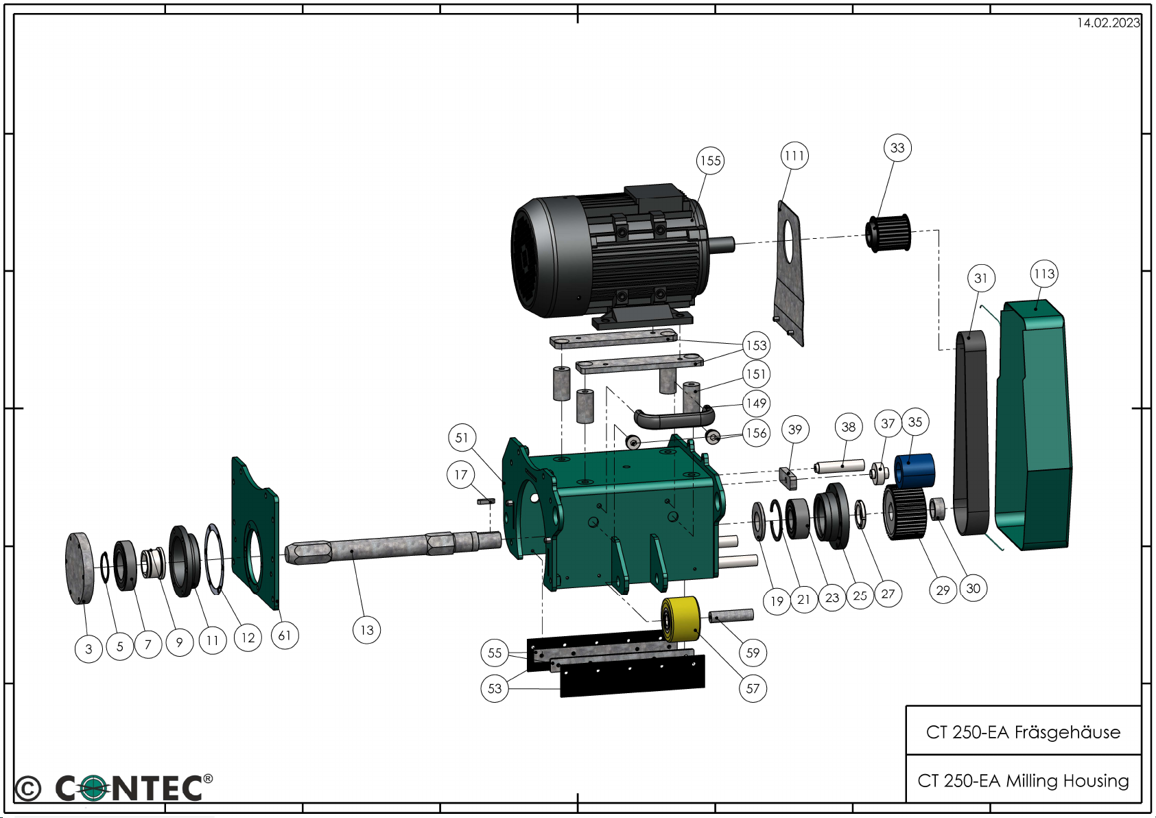
Vorschubwalzen (Anhang S izze Pos 119)
von den Hinterrädern abheben. Dazu muss der
Hebel Höhenschnellverstellung (Anhang
S izze Pos 97/99) nach oben gezogen werden.
b To move the floor planer lift the drive
wheels (Appendix diagram No. 119) from the
rear wheels of the machine. Therefor the lever
of the height adjustment (Appendix diagram
No. 97/99) has to be brought to its upper
position.
c Der Hebel Höhenschnellverstellung der
Fräse muss sich vor dem Einschalten des
Motors in oberer Stellung befinden.
Außerdem muss das Handrad (Anhang S izze
Pos 101/102) der Maschine im Uhrzeigersinn
bis zum Anschlag gedreht werden.
c The lever of the height adjustment has to be
in the upper position before the machine is
switched on. The hand wheel (Appendix
diagram 101/102) of the height adjustment
must also be turned cloc wise as far as
possible.
d Das Potentiometer der Vorschubgeschwin-
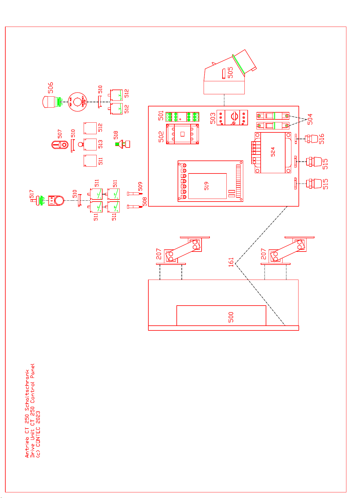
dig eit (Anhang S izze Pos 518) auf der
Oberseite des Schaltschran s auf „0“ drehen.
Der Fräsmotor ann jetzt mit Hilfe des
Motorschalters (Anhang S izze Pos 507)
eingeschaltet werden.
d Turn the potentiometer for the speed
regulation (Appendix diagram No. 518) on
top of the control panel into the „0“ position.
The motor of the planer can now be switched
on by pressing the motor switch (Appendix
diagram No. 507).
e Die Fräse wird jetzt abgelassen indem der
Hebel Höhenschnellverstellung nach unten
geschoben wird. Die Arbeitstiefe mit dem
Handrad der Höhenregulierung (Anhang
S izze Pos 101/102) soweit einstellen, bis die
Wer zeuge auf dem Boden greifen und der
gewünschte Effe t erzielt wird.
e Lower the planer with the lever to the
operating position. Turn the hand wheel of the
height adjustment (Appendix diagram
101/102) until the tools are lowered onto the
floor and until the desired finish is achieved.
Achtung: Übermäßige Tiefeneinstellung
führt zur Anhebung der Maschine. Es
besteht die Gefahr, dass die Fräse sich
nach vorne in Bewegung setzt. Die
mögliche Tiefeneinstellung ist von der
Härte des Bodens abhängig und muss von
Fall zu Fall ermittelt werden
Attention: Lowering the tools too much
will lift the machine from the floor. The
machine can jump forward. How deep you
can go depends on the hardness of the
floor.