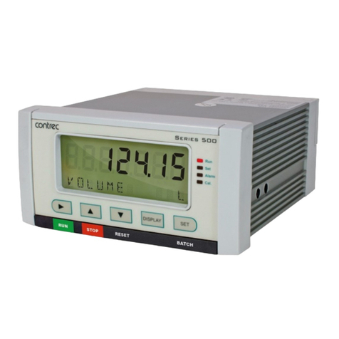
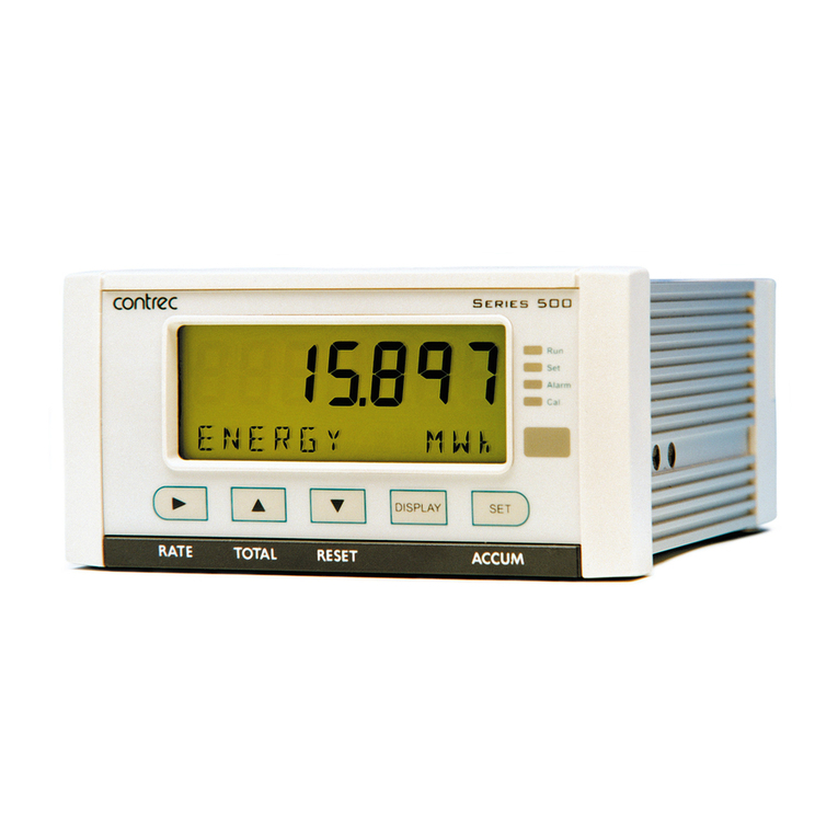
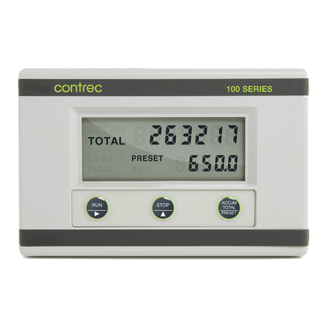
Contrec 214D User manual

214D-M-V7
FIELD MOUNTED
BATCH CONTROLLER
MODEL 214D
May 2019


CONTENTS
1. Introduction 1
1.1 Model Number Designation 3
1.2 Intrinsic Safety Approvals 4
2. Specification 6
3. Operation 8
3.1 Front Panel Operation 8
3.2 Test Mode 10
3.3 Batch Operations 11
3.3.1 Control Outputs 11
3.3.2 Signal Timeout 12
4. Programming 13
4.1 Program Steps 14
4.2 Example 15
5. Valve Control and DC Power 16
6. Battery Backup Version 18
7. Flowmeter Input 19
8. Intrinsic Safety Connections 24
8.1 Coils 24
8.2 Simple Apparatus 25
8.3 Namur Proximity Switches 25
8.4 Relay Outputs 27

9. Installation 29
9.1 Wall Mounting 29
9.2 Panel Mount Version 30
9.3 Removing the Front Panel 31
9.4 The Main Electronics 33
9.5 Grounding 33
9.6 Wiring 34
9.7 Maintenance 34
9.9 Dimensions 35
9.10 Terminal Designations 36
9. Instrument Disposal 37
Index 38

Introduction 1
1. INTRODUCTION
The Model 214Di Batch Controller is a microprocessor based instrument
which accepts a frequency or pulse input from a wide range of
flowmeters
and automatically controls the batching of fluids via a one stage or two
stage control valves. The instrument displays the Preset value, a
Resettable
Batch Total and an accumulated Total directly in engineering units.
The Batch Controller is intrinsically safe and can be used in hazardous
areas provided it is connected as directed to approved flowmeters and
control solenoids.
The Model 214Di is fully programmable from the front panel; the
user
can program scaling factors, decimal point positions, valve delays and
signal timeouts.
The instrument is compatible with a wide range of flowmeters. Links on
the
input board enable the circuit to be configured for millivolt signals, reed
switches, Namur proximity switches and most other signal types.
The instrument is housed in an attractive polycarbonate enclosure
which
is completely watertight. A universal bracket is supplied as standard
for
wall mounting while optional pipe or panel mounting brackets are
also
available.
The Model 214D is an upgraded version of the Contrec Model 214. The
following improvements have been made in the Model 214D:
� The voltage drop across the solenoid outputs in the 214D is only 0.8
Volts.
� The voltage supply for the DC input can go as low as 9 Volts.
� The 214D has an overall lower current consumption than the
previous
model with an improved battery life - the battery life in the new
model is typically 5 years regardless of the time the unit spends in
totalising or batching modes.
� The millivolt input can accept signals as low as 15mV P-P.
�The 214D has a wide frequency range - 0Hz to 10kHz.
Introduction2
The Model 214Di Rate Totaliser conforms to the EMC-Directive of the Council of
European Communities 2014/30/EU, the LVD directive 2014/35/EU and the following
standards:
EN61326:2013 Electrical equipment for measurement, control and
laboratory use – EMC requirements :
Residential, Commercial & Light Industry Environment
& Industrial Environment.
EN61010:2010 Safety requirements for electrical equipment for
measurement, control, and laboratory use.
In order to comply with these standards, the wiring instructions in Section 9.5
must be adhered to.

Introduction 3
1.1 MODEL NUMBER DESIGNATION
The Model Number of the 214Di describes the unit type, output and
backup options installed and the mounting options.
Model 214Di . 2 0 C . A
Model
Intrinsically Safe
Batch Controller - 214Di 0 - Standard solid state relay
outputs
Type of Mounting
0 - No cable entry holes
1 - Panel mount
2 - Wall mount with cable glands
6 - 2" galvanised pipe bracket
Enclosure Type*
A - Aluminium
Approvals
C CSA USA / Canada approval
M ATEX/IECEx approval
eg. Standard wall mounted Batch Controller would be Model 214Di.20M
* 214D is supplied in plastic enclosure as standard unless ‘A’ is stated in part
number.

Introduction
4
1.2 INTRINSIC SAFETY APPROVALS
The Model 214Di is certified for use in hazardous areas and has IECEx, ATEX
and CSA US/C approvals.
The Model 214Di certification details are:
IECEx Approval IECEx BVS 15.0099X
Rat i n g E x i a IIB T 4 Gb
ATEX Approval BVS 15 ATEX E 106 X
Rating II 2G Ex ia IIB T4 Gb
Ambient Temperature: Maximum ambient temperature of -20° to-60°C.
CSA US/C Approval LR 104 840-5.
Type: Class 1, Groups C and D.
When installing in hazardous areas, the instrument must be installed
according to the guidelines in Section 8 and in accordance with standards for
wiring and installation in hazardous areas.
DC Power
The input can be connected to IS circuits with the following maximum
values:
Ui = 28V
Ii = 93mA
Pi = 653mW
The internal capacitance and inductance seen on these terminals is 0.1uF
and 0mH.

Introduction 5
Relay Outputs
The outputs can be connected to IS circuits with the following
maximum values:
Ui = 28V
Ii = 93mA
Pi = 653mW
The internal capacitance and inductance seen on these terminals is 0.1uF
and 0mH.
Flowmeter Input
Entity parameters on the flowmeter enable connection to a wide
range of approved sensors.
Input parameters are:
Ui = 24V
Ii = 20mA
Pi = 320mW
The internal capacitance and inductance seen on these terminals is 0.02uF
and 0mH.
Output parameters are:
Uo = 10.0V (open circuit)
Io = 9.0mA (short circuit)
Po = 23mW
Maximum allowed external capacitance is 20µF.
Maximum allowed external inductance is 1.5H.

Specification6
2. SPECIFICATION
General
Display: LCD which is continuously powered.
Batch Total: 7 digits with 10mm (0.4") high digits.
Accumulated Total: Displayed when the ACCUM TOTAL button is
pressed.
Preset: 5 digits with 8.5mm (0.33") high digits.
K-factor: The pulses per unit of measure (e.g.
pulses/gallon) is programmable in the range
0.0001 to 999,999.
Decimal Points: Decimal point position is fully programmable
for the total and preset.
Frequency Range: 0Hz to 10kHz.
Signal Type: Link settable for sinewave (15mV P-P minimum),
open collector, reed switch, pulse or
Namur proximity switch.
DC Power Input: 9-28 Volt at 4mA maximum.
Battery Backup
Type: Two lithium battery packs.
Battery Life: 5 years typical.
Outputs
Outputs: Two solid state relay outputs suitable for
driving DC solenoids or external relays.
Switching Power: 200mA. 30VDC maximum.
Supply Backup: Lithium battery.
Isolation: Both outputs are separately isolated via
opto-isolators.

Specification 7
Physical
Temperature: Operating temperature: -20°C to 60°C.
Dimensions: 98mm (3.9") high x 152mm (6.0") wide x
43mm (1.7") deep (cable glands not included).
Protection: Sealed to Nema 4X or IP67 standards.
Cable Entry: By cable glands.
Material: Polycarbonate and ABS.
Wall Mounting: Universal mounting bracket supplied as standard.
Pipe Mounting: A galvanised metal bracket is available
which enables the Model 214Di to be
attached to a 2" vertical or horizontal pipe.
Turbine Meter Adaptor: An optional mounting stem is available
for mounting the Model 214Di directly on
turbine flowmeters which have a 1" NPT
boss or 1" BSP boss.
Panel Mounting: Supplied with mounting brackets.
Terminals accessible from rear. The panel
mount version is not watertight.
Cutout: 142mm (5.6") wide x 88mm (3.5" high).

Operation8
3. OPERATION
The Model 214Di Batch Controller accepts a frequency or pulse input from a
wide range of flowmeters. The instrument is fully programmable with all
operating parameters and calculation constants programmable from the front
panel. The setup parameters are stored in a non-volatile memory and are
retained for at least 10 years in the event of a power loss.
3.1 FRONT PANEL OPERATION
Three keys on the front of the instrument provide an easy and straight
forward method to set up batches and control operations. The three keys
each have dual functions as described below:
Front Panel Keys
SETTING THE PRESET QUANTITY
The Batch quantity is programmed as follows:
Switch Action Display Comments
Press PRESET The Accumulated Total together with
the Preset quantity is displayed.
"1" 2345
The most significant digit of the Preset
quantity flashes indicating that it can
be changed.
Press "2" 2345 Pressing the < key will increment the digit.
(The up arrow on the Stop key indicates
to increment the digit.)
STOP
RUN
ACCUM
TOTAL
PRESET

Operation 9
Switch Action Display Comments
Press 2 "2" 345 Pressing the key will change digit and
enables the next digit to be
incremented.
(The right arrow on the RUN key indicates
to change digit.)
Press PRESET 22345 Pressing PRESET returns the instrument
to the Run mode and batches can now be
run.
Note: If there are no keys pressed within 10 seconds while the instrument is
in preset mode it will return to the run mode saving the current value as the
preset quantity.
Upon exit of preset mode the value is checked against the programmable
batch limit. If the value is greater than the batch limit the preset value is
set to the programmed limit. This check is disabled if the batch limit is
programmed as zero.
Once programmed, the Preset quantity will be retained in memory and will
not alter until changed by the user. The Preset quantity can only be set
while the instrument is in a non-operational state such as when the batch
is complete, or has been cancelled.
STARTING A BATCH
To start a batch press the RUN key. The Total will then reset to zero and,
provided there is flow, the Total display will start counting upwards.
The batcher has two output transistors and these are switched on and
off as described in section 3.3.
STOPPING
The process can be stopped at any time by pressing the STOP switch. This
is indicated by the "Pause" message being displayed on the screen. Once
the process has been interrupted in this way, it can be continued by
pressing the RUN key or the process can be aborted by pressing the STOP
switch a second time.

Operation10
ACCUMULATED TOTAL
During a batch run, the Accumulated Total can be displayed by pressing
the ACCUM TOTAL key. In the non-operational state (i.e. when the batch
is complete), the ACCUM TOTAL key also functions as the PRESET key and
enables the Preset quantity to be changed.
The Accumulated Total cannot normally be reset, except by pressing the
internal Reset button (see section 9.4).
3.2 TEST MODE
The 214Di has a Test Mode which can be entered and exited by pressing
and holding the front panel keys in certain sequences to avoid accidental
entry or falsely starting a batch. To enter Test Mode, the front panel keys
should be pressed and held in the following order: the STOP key and then
the ACCUM TOTAL key.
Note the test mode cannot be entered while the instrument is in program
mode or preset mode.
The tests are as follows:
Relay 1 Test By pressing the RUN key, the display will show
the test for Relay 1. The output will only
activate while the RUN key is being pressed.
Relay 2 Test By pressing the STOP key, the display will show
the test for Relay 2. The output will only
activate while the STOP key is being pressed.
Display Test By pressing the PROGRAM key, all segments of
the display will flash.
Note the relay outputs are only operated when external DC power is present.
And any batch in progress when test mode is entered is stopped and cannot be
resumed.
To exit Test Mode, the front panel keys should be pressed and held in
the following order: the ACCUM TOTAL key and then the STOP key.

Operation 11
3.3 BATCH OPERATIONS
The operation of the Batch Controller is shown below:
3.3.1 Control Outputs
The two solid state relay outputs can be set up to control a single valve or a
dual valve with slow stop and/or slow start. Alternatively, the second output
can be used to control a pump.
The output operation is shown above.
A time delay between the Start and the time when Output 2 switches on
can be programmed to provide a soft startup. The delay can range from 0
(no delay) to 9 seconds.
A Prestop quantity (i.e. the quantity to the end of the batch) can also
be programmed to provide a slowdown of flow at the end of the
batch, thereby enabling precise quantities to be batched.
Run
PAUSE
Stop Run
Batch
Quantity
Reached Run
Output 1
Output 2
"on" state
"on" state
Start Time Prestop
Quantity
Two Stage Valve Control

Operation12
The process can be stopped at any time by pressing the STOP key, whereby
both outputs will immediately switch off. The process can then be aborted
and the batcher reset by pressing the STOP key again, or the process
continued by pressing the RUN key.
If the process is continued and the instrument was previously in the slow
start or main control phases (i.e. not the prestop phase), the timer will be
reset and a slow start will occur with a full time delay to ensure a correct
start up. The totals will not be reset and the batch quantity will remain
unchanged.
3.3.2 Signal Timeout
The Signal Timeout period defines a time interval which is used to detect if
the low has stopped. If there is no signal input for a time greater than the
Signal Timeout period, the flow is deemed to have stopped. A Signal
Timeout period detects the loss of signal midway through a batch when the
outputs are on. In this case, the Batcher will enter a Flow Alarm condition
and switch off the outputs.
The Flow Alarm condition is maintained until acknowledged by pressing the
STOP switch. The alarm condition is also signalled to the operator by the
PAUSE message being flashed on the display.
The instrument enables the user to program a time interval of up to 99
seconds to detect an absence of signal input.
If the Signal Timeout is set to 0, this function is disabled.

Programming 13
4. PROGRAMMING
The Model 214Di is fully programmable, with all parameters being stored
in memory.
The Program Mode can be entered in one of two ways:
1. By removing the lower cover strip (i.e. the dark grey strip along the
bottom of the enclosure) and turning it end for end and replacing it.
This brings a small magnet, on the inside of the cover strip, in close
vicinity of a reed switch inside the instrument.
2. By removing the front section of the enclosure which contains the
main processor board and batteries. Once removed, the PRESET key
is pressed to enter the Program Mode.
The PRESET switch is used to step through the program (CAL sequence) and
the and keys on the front panel are used to change and increment the
flashing digits. Six CAL steps are accessible in the Calibration mode. The CAL
number is displayed on the lower display and the parameter is displayed on
the upper display.
Any batch in progress when the Program mode is entered, is stopped and
cannot be resumed. Also, no incoming pulses are totalised while the unit is in
Program mode.
To exit the Program mode the lower cover strip should be returned to its
original position or the front panel should be refitted.
Parameters in Program Mode that consist of the two parts, whole numbers
and digits after the decimal point, are restricted to having a maximum of 6
significant digits. Therefore the number of significant digits entered in the
whole numbers determines the number of digits that are able to be entered
in the digits after the decimal point.
For Example
000001 in the whole numbers makes 0000 available after the decimal place.
000100 in the whole numbers makes 000 available after the decimal place.
010000 in the whole numbers makes 0 available after the decimal place.

Programming
14
4.1 PROGRAM STEPS
Step Comment
Scaling Factor - whole numbers.
Scaling Factor - digits after the decimal point.
The Scaling Factor is the pulses per unit of measure
(e.g.pulses/litre, pulses/gallon, etc). The Scaling Factor
can be programmed in the range of 0.0001 - 999,999.
Decimal Point for Total Display.
The total and preset quantity can be displayed with 0, 1,
2 or 3 decimal point places.
Start Time Delay.
The time in seconds (0-9 sec) when Output 2 will
switch "on" once the RUN key is pressed.
Prestop Quantity
The quantity at which Output 2 will switch "off"
before the end of the batch (Eg. If the Preset quantity
is 100 litres and the Prestop quantity is 2 litres,
Output 2 will switch off after 98 litres.)
Signal Timeout.
A time period between 0-99 seconds during which,
if there is no flow measured, the Outputs will both
switch "off" and the PAUSE message will be
displayed.
Batch Limit.
This value determines the maximum preset value
that may be entered by the operator. A value of
zero for the batch limit disables this feature.
Software Version.

Programming 15
4.2 EXAMPLE
A flowmeter produces 20.538 pulses per litre and has a maximum flowrate of
150litres/minute. It is required to batch quantities in batches of around 300
litres and to alarm if there is no flow once the batch has started.
To increase the accuracy of the batch, a two stage valve will be used and the
flow will be slow prior to the end of the batch to enable a more accurate
cutoff.
It has also been decided to reduce the flowrate 10 litres prior to the end of
the batch. The instrument is then programmed as follows:
Step
Value of
Parameter Description
00020 Scaling factor (Whole numbers).
5380 Scaling factor (Decimals).
1 One decimal place.
1 One second delay on full flow to
stop pipe hammer.
10 10 litre prestop.
2 Two second signal timeout.
350 350 litre batch limit.
2.XX Software Version.

Valve Control and DC Power
16
5. VALVE CONTROL AND
DC POWER
The Model 214Di will operate from an external power source between 9-
28VDC and draws no more than 4mA. This enables the instrument to be
powered from AC mains adaptors and eliminate the need to run mains
voltage in the field.
As the instrument has an internal battery backup it will power the instrument if
DC power is interrupted, but these batteries are not capable of powering the
solenoids or sensors if they require external power (see section 6 for further
description of operation with battery backup.)
Solid state relay outputs provide control to solenoids or relays and can sink
up to 200mA. The outputs are internally protected against voltage spikes
caused by relays and coils. Connections for a dual stage applications is given
on the following page.
For single stage applications, only Output 1 is required.
Specification for Outputs
Maximum Current (sink): 200mA.
Maximum Voltage: 30VDC.
Saturation Voltage: 0.8VDC max across the outputs in the "on"
state.
This manual suits for next models
1
Table of contents
Other Contrec Controllers manuals

Contrec
Contrec 515 User manual

Contrec
Contrec 500 Series User manual

Contrec
Contrec 424 User manual

Contrec
Contrec 515 User manual

Contrec
Contrec 515 User manual

Contrec
Contrec 414Q User manual

Contrec
Contrec 414L Reference manual

Contrec
Contrec 505 BC01 User manual

Contrec
Contrec 505 Series User manual

Contrec
Contrec 515 CB01 Installation manual
Popular Controllers manuals by other brands

Fermax
Fermax STAND-ALONE CONTROLLER 1 DOOR WG Installer manual

OSTLING
OSTLING PinMark UMC box Operation manual

Allen-Bradley
Allen-Bradley PowerFlex 700H Service manual

Siemens
Siemens SIMATIC ET 200SP operating instructions

Belimo
Belimo NM24A-MP Technical data sheet

MarelliMotori
MarelliMotori MARK X user manual