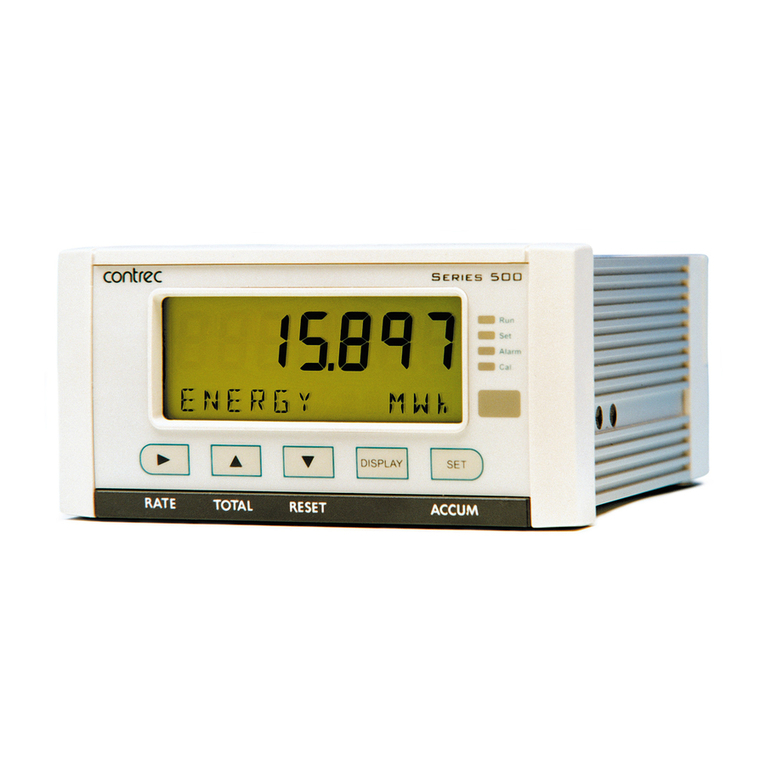
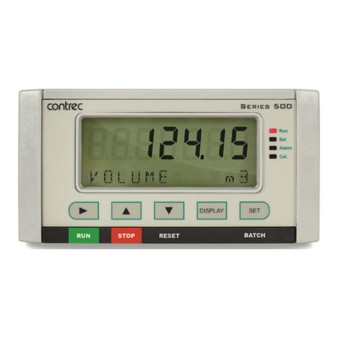
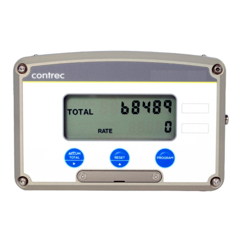
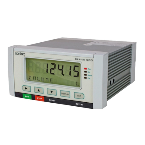
Contrec 424 User manual

424-M-V1.5
BATCH CONTROLLER
MODEL 424
22 Jun 2018

424-M-V1.5

424-M-V1.5
Contents
1. INTRODUCTION 1
1.1 MODEL NUMBER DESIGNATION 3
2. SPECIFICATION 4
3. OPERATION 6
3.1 FRONT PANEL OPERATION 7
3.2 BATCH OPERATIONS 10
3.2.1 Control Relay Outputs 12
3.2.2 Signal Timeout 13
3.2.3 End of Batch 14
3.2.4 Auto Restart 15
3.2.5 Automatic Overrun Compensation 16
3.3 CALCULATION OF RATE AND TOTAL 17
3.3.1 Frequency Input 17
3.3.2 Filtering 18
3.4 TOTAL CONVERSION 20
3.5 THE OUTPUT PULSE AND FLOW ALARM 21
4. COMMS & OPTIONS 23
4.1 THE RS232/485 INTERFACE 23
4.1.1 Hardware 23
4.1.2 RS232 24
4.1.3 Multipoint Communication 25
4.1.4 Real Time Clock 26

424-M-V1.5
4.2 SOFTWARE PROTOCOL 27
4.2.1 Echoing Commands 27
4.2.2 Response Times 27
4.3 COMMANDS AND RESPONSES 28
4.4 PRINTER COMMUNICATIONS 31
4.4.1 Hardware Interconnection 31
4.4.2 Operation 33
4.4.3 Information Printed 33
4.5 THE 4-20mA OUTPUT OPTION 36
4.5.1 Load Specification 37
4.5.2 Calculation 37
5. CALIBRATION 39
5.1 PROGRAMMING THE SETUP PARAMETERS 41
5.2 ENTERING THE BATCH PARAMETERS 43
5.3 PROGRAMMING OPTIONS 45
5.4 TEST MENU 48
6. INPUT CIRCUITS 49
6.1 INPUT CIRCUIT FOR THE MODEL 424 49
6.2 FREQUENCY INPUT CONNECTION 50
6.3 REMOTE SWITCHES 52
7. INSTALLATION & MAINTENANCE 53
7.1 GENERAL 53
7.2 WIRING DESIGNATIONS FOR THE 424 55

424-M-V1.5
7.3 MAINTENANCE 56
8. TROUBLE SHOOTING 57
8.1 ERROR CODES 59
Index 60

424-M-V1.5

424-M-V1.5
Safety Notice
The information in this safety notice is for the prevention of injury to personnel
and damage to the instrument.
Use only in accordance with the instructions provided within this manual.
The manufacturer assumes no liability for injury or damage caused by misuse of
the instrument or modifications made to the instrument.
Qualified Personnel & Maintenance
The instrument must be installed, operated and serviced by persons who have
been properly trained and authorised. Personnel must read and understand this
manual prior to installation and operation of the instrument. Refer to section 7
for further information regarding permitted maintenance operations.
Static Hazard
The user should observe accepted safety practices for handling electronic
devices, especially during servicing.
Voltage Hazard
Before connecting power to the instrument, ensure that the supply voltage for
the AC or DC input is suitable. The AC voltage rating is as stated on the
instrument rating plate. Personnel should take all due care to avoid electric
shock. For safe operation it is essential to connect a mains safety earth to the
A.C. Power inlet. Do not operate at altitudes above 2000m.
Welding Hazard
Do not perform electric welding in close proximity to the instrument or its
interconnecting cables. If welding in these areas must be performed, disconnect
all cables from the instrument. Failure to do so may result in damage to the unit.
Moisture Hazard
To avoid electrical faults and corrosion of the instrument, do not allow moisture
to remain in contact with the instrument. Operate only in a clean, dry and
pollutant-free environment.
Disconnection Device
When powered from a mains supply this unit requires the provision of a suitable
mains isolation device, capable of interrupting both poles of the supply and
meeting your local wiring regulations, to be accessible near to the installed
instrument.
424-M-V1.5
FCC Notice
This equipment has been tested and found to comply with the limits for a
Class A digital device, pursuant to Part 15 of the FCC Rules. These limits are
designed to provide reasonable protection against harmful interference
when the equipment is operated in a commercial environment. This
equipment generates, uses, and can radiate radio frequency energy and, if
not installed and used in accordance with the instruction manual, might
cause harmful interference to radio communications. Operation of this
equipment in a residential area is likely to cause harmful interference, in
which case the user will be required to correct the interference at his own
expense.
Properly shielded and grounded cables and connectors must be used in order
to meet FCC emission limits. Contrec Ltd. is not responsible for any radio or
television interference caused by using other than recommended cables and
connectors or by unauthorized changes or modifications to this equipment.
Unauthorized changes or modifications could void the user's authority to
operate the equipment.
This device complies with Part 15 of the FCC Rules. Operation is subject to the
following two conditions: (1) this device might not cause harmful
interference, and (2) this device must accept any interference received,
including interference that might cause undesired operation.

424-M-V1.5
Introduction 1
1. INTRODUCTION
The model 424 Batch Controller accepts pulse or frequency flow signals
and automatically controls the batching of fluids via a one or two stage
control valve.
The instruments are extremely flexible and easy to operate, with a four key
front panel operation that enables the batch quantity to be set, and batches
to be started or stopped.
This manual covers both the Model 424.0 and 424.1. While both versions
have identical software and outputs, the Model 424.1 includes a 4-20mA
output circuit.
Model 424 Accepts most frequency and pulse signals,
including mV outputs from turbine flowmeters,
and 2 wire proximity switch outputs. It also
enables all four front panel switches to be
remotely connected via the rear terminal strip.
The Model 424 has a scaled pulse output for driving
remote counters, together with a flow alarm output.
The instrument is fully programmable, with all calculation constants set via the
front panel switches and stored permanently in non-volatile memory.
This instrument is intended for fixed installation only, e.g. within a panel or
cabinet, and is not intended for desktop use.

424-M-V1.5
2 Introduction
This instrument conforms to the EMC-Directive of the Council of
European Communities 2014/30/EU, the LVD directive 2014/35/EU and
the following standards:
• EN61326:2013 Electrical equipment for measurement, control and
laboratory use – EMC requirements:
Residential, Commercial & Light Industry Environment & Industrial
Environment.
• EN61010:2010 Safety requirements for electrical equipment for
measurement, control, and laboratory use.
In order to comply with these standards, the wiring instructions in Section 7.1
must be followed.

424-M-V1.5
Introduction 3
1.1 MODEL NUMBER DESIGNATION
The model number of an instrument describes which input and output options
are installed.
Model 424 . 1 0 U C
C for Conformal Coating
The model and option of the instrument can be displayed in the Test Menu
(sec 5.4).
Options
0 for no option
1 for 4-20mA Output
Power
U for universal mains supply
D for DC power only
Mounting
1 for Panel Mounting
2 for Field Mounting (contact factory)
3 for Explosion proof

424-M-V1.5
4 Specification
2. SPECIFICATION
General
Display: 6 digit LCD. 0.7" (17.8mm) high digits.
Display Update Rate: 0.25 seconds.
Transducer Supply: 8-24VDC software adjustable, 0.2, 0.5, 1V
increments.
70mA max @ 24V, 120mA max @ 12V.
Power Requirements: 13.5 to 28.5 volts DC, 10W.
AC Mains: 100-240 V AC (+/-10%) 50-60 Hz (+/-10%), 10W
Operating Temperature: 0 to 55°C standard.
-20°C to 60°C with conformal coating option.
Dimensions: 5.7" (144mm) wide x 2.8" (72mm) high x
7.0" (178mm) deep.
Cutout: 5.5" (139mm) wide x 2.6" (67mm) high.
Installation: This instruments is intended for fixed
installation only, e.g. within a panel or
cabinet, and is not intended for desktop
use.
Frequency Input
Frequency Range: Minimum: 0.25Hz on Rate.
0Hz on Total.
Maximum: 10KHz - Pulse, 2.5KHz Coil and
NPS
Input Circuits: Will accept most sine logic and proximity
switch inputs (see section 6.1).
Scaling Range: 0.1000 to 50,000.
Relay Outputs
Maximum Switching Power: 1250VA.
Maximum Switching Voltage: 250VAC, 30VDC.
Maximum Switching Current: 5 Amps.

424-M-V1.5
Specification 5
4-20mA Output
Resolution: 12 bits.
Accuracy: Better than 0.1%.
Maximum Load: 390 ohms internally powered from +15V
(Terminal 3, +15V and 6, 0V )
950 ohms from 24Vdc or if internal I (-) = -15V
(Terminal 3, +15V and 7, -15V )
See page 38.
Isolation: Output is isolated.
Pulse Output
Pulse Width: 1,10,100mSec (negative going pulse).
Maximum Duty Cycle: 499,49,4.9 pulses per second - according to
pulse width setting.
Output: An open collector transistor will sink
100mA.
Scaling: The pulse output is scaled and outputs one
pulse each time the accumulated total
increments to its maximum limit.
E.g. With a pulse width setting of 10mSec the unit can output a maximum of 50
pulses per second. The scaling of t.dpt must be set so that the least significant
digit of the accumulated total does not exceed 50 increments per second (Hz).

424-M-V1.5
6 Operation
3. OPERATION
The model 424 Batch Controllers use a low power CMOS microprocessor
to perform all control functions and calculations.
The instruments are fully programmable with all operating parameters and
calculation constants user programmable. (See Section 5 entitled
'Calibration' for information on programming). All parameters and constants
are stored in a non-volatile memory which retains data without battery
backup for a minimum of 10 years.
A block diagram of the instrument is shown below.
Pulse Input
Signal
Common
RS232/485
Comms
DC Input Power
DC Power Ground
DC Power Output to Sensors
Model 424
RS232/485
Relays
End Of Batch (EOB) /
Pump Control (PC)
110-220V
AC Mains
Control
Relay Outputs (2)
Pulse
Output
Flow Alarm
4-20mA
Output
4-20mA
Output
Remote
Switches

424-M-V1.5
Operation 7
3.1 FRONT PANEL OPERATION
The four key operation of the Batch Controller is straightforward.
SETTING THE BATCH QUANTITY
The Batch quantity is programmed as follows:
Switch Action Display Comments
Press BATCH SET Batch 'Batch' is displayed for one second
followed by the batch quantity last
entered. The Batch Set LED lights.
'1' 2345 The most significant digit flashes
indicating that it can be changed.
Press '2' 2345 Pressing the DISPLAY key will
increment the digit. (The up arrow on the
Display key indicates to increment digit).
Press 2 '2' 345 Pressing the RUN key will change digit
and enable the next digit to be
incremented. (The right arrow on
the RUN key indicates to change
digit).
Press BATCH SET Set Once the desired number is entered,
press the BATCH SET key to return to the
Run mode. The Batch Set LED will
extinguish.
Once programmed, the Batch quantity will be retained in the non-volatile
memory and will not alter until changed by the user.

424-M-V1.5
8 Operation
The Batch quantity can only be set while the instrument is in a non-operational
state such as when the batch is complete, or if the batch process has been
interrupted.
However, the BATCH SET key can be pressed and held while in the run
state to check the current Batch quantity. All digits will flash to signal the
quantity cannot be changed.
STARTING A BATCH
To start the process the RUN key is pressed. The Run LED will light green
and the instrument will begin to totalise from zero or, if programmed for
the count down mode, the display will decrement from the batch quantity.
The Batch Controller has two output relays and these are energised and de-
energised as described in Section 3.2.
STOPPING
The process can be stopped at any time by pressing the STOP key. Once the
process has been interrupted in this way it can be continued by pressing the
RUN switch, or the process can be aborted and the instrument reset by
pressing the STOP switch a second time.
When the process is interrupted, the STOP LED will flash to prompt the
operator to either restart or abort the batch.
RESETTING
The instrument can be programmed to reset in one of two ways :-
�At the end of a batch, the STOP key must be pressed to reset
the Batch Total. If the instrument is programmed to count down,
the Batch Total will then revert to the preset quantity. If it is
programmed to count up, the Batch Total will clear to zero.
�If Auto Reset is programmed, the Batch Total will automatically
reset when the RUN key is pressed and then commence the
next batch.

424-M-V1.5
Operation 9
DISPLAYED INFORMATION
The display will normally show the Batch Total, which is the total count for
the current batch and is reset on each new batch.
The DISPLAY key can be used to display the following additional information:
Rate
On the first press of the DISPLAY key, the display shows RATE for one
second followed by the flowrate.
Accumulated Total
On the next press of the DISPLAY key, the display shows ACCtot for
one second followed by the actual total. The Accumulated Total
cannot be reset during normal operation.
Changes to the delivery status, e.g. Starting or reaching the end of a batch,
take priority and the display will be restored to showing the batch values.
LIMIT ON BATCH SIZE
To prevent accidental entry of large batch quantities, a maximum batch limit
can be programmed during calibration. The operator is then prevented from
entering a batch quantity which exceeds this value.

424-M-V1.5
10 Operation
3.2 BATCH OPERATIONS
The Batch Control functions can be programmed during Calibration to operate
in one of two ways :-
1. At the end of the batch, the STOP key must be pressed to reset the Batch
Total. (This must be done before another batch can be started).
Run
PAUSE
Stop Run Stop Run
Relay 1
Relay 2
Start Time Prestop
Quantity
End of
Batch End of
Batch
Count Down
Count Up
Batch
Quantity
Reached

424-M-V1.5
Operation 11
2. If Automatic Reset is programmed, a new batch is commenced each time
the RUN key is pressed.
The Batch Controller can also be programmed, during Calibration, to either
count up from zero on each batch, or to count down from the preset batch
quantity.
Batch
Quantity
Reached
Run
PAUSE
Stop Run Run
Relay 1
Relay 2
Start Time Prestop
Quantity
End of
Batch
Count Down
Count Up
End of
Batch
Auto Restart
Time

424-M-V1.5
12 Operation
3.2.1 Control Relay Outputs
The two output relays can be set up to control either a single valve or a dual
valve with slow stop and/or slow start. Alternatively, the second relay can be
used to control a pump.
The relay operation is shown on the previous two pages.
A time delay between the Start and the time when relay 2 energises can
be programmed to provide a soft startup. The delay can range from 0
(no delay) to 79 minutes and 59 seconds.
A Prestop quantity (i.e. the quantity to the end of the batch) can also
be programmed to provide a slowdown of flow at the end of the
batch, thereby enabling precise quantities to be batched. The Prestop
value is limited by the number of decimal points used for the total
(t.dpt, Cal Menu).
The process can be stopped at any time by pressing the STOP key, whereby
both relays will immediately de-energise. The process can then be aborted
and the Batch Controller reset by pressing the STOP key again, or the process
continued by pressing the RUN key.
If the process is continued and the instrument was previously in the slow
start or main control phases (i.e. not the prestop phase), the timer will be
reset and a slow start will occur with a full time delay to ensure a correct
start up. The totals will not be reset and the batch quantity will remain
unchanged.
t.dpt Max Prestop
0 10,000
1 1,000
2 100
3 10
Table of contents
Other Contrec Controllers manuals

Contrec
Contrec 414L Reference manual

Contrec
Contrec 515 User manual

Contrec
Contrec 515 CB01 Installation manual

Contrec
Contrec 214D User manual

Contrec
Contrec 505 BC01 User manual

Contrec
Contrec 500 Series User manual

Contrec
Contrec 515 User manual

Contrec
Contrec 505 Series User manual

Contrec
Contrec 515 User manual

Contrec
Contrec 414Q User manual