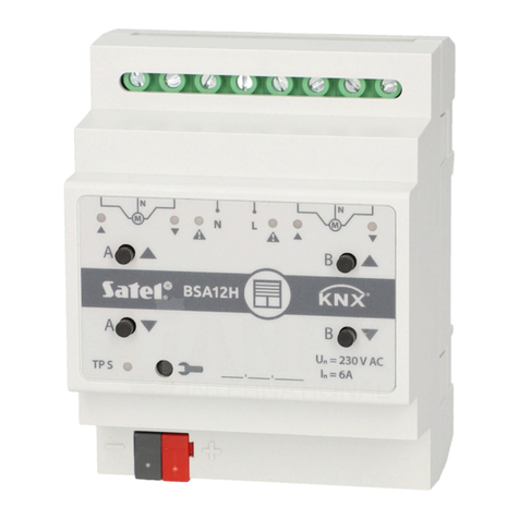
Satel KNX-SA41 User manual

KNX-SA41 / KNXSA24
Universal Switch Actuator
Quick installation guide
Full manual is available on www.satel.eu
Firmware version 1.01 knx-sa_sii_en 11/19
SATEL sp. z o.o. •ul. Budowlanych 66 • 80-298 Gdańsk • POLAND
tel. +48 58 320 94 00
www.satel.eu

IMPORTANT
The device should be installed by qualified personnel.
Prior to installation, please read carefully this manual.
Changes, modifications or repairs not authorized by the manufacturer shall void your rights
under the warranty.
SATEL aims to continually improve the quality of its products, which may result in changes in
their technical specifications and software. Current information about the changes being
introduced is available on our website.
Please visit us at:
http://www.satel.pl
The declaration of conformity may be consulted at www.satel.eu/ce
The following symbols may be used in this manual:
- note;
- caution.

This manual only regards the installation of modules KNX-SA41 and KNX-SA24. For more
information about modules and their configuration, please refer to the full manual available at
www.satel.eu.
1. Description
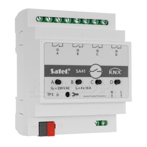
The KNX-SA41 / KNX-SA24 module is an universal switch actuator, which makes it possible
to control electrical devices (lighting, ventilation).
The modules differ by the number of outputs, the KNX-SA41 having four and the
KNX-SA24 eight relay outputs (see “Electric diagram of relay outputs”).
load circuit terminals for connecting loads (2 terminals per channel).
green LEDs indicating the channel state. One channel state LED is assigned to each
channel:
ON –channel enabled,
OFF –channel disabled.
buttons to manually change the channel state. One ON/OFF button is assigned to each
channel.
The manual change of channel state is monitored by the module. The values of
communication objects responsible for storing information about the current state of
individual channels are systematically updated, according to the changes made.
The buttons are also used to restore the module factory default settings (see
“Restoring the module factory default settings”).
red LED –is ON when physical address is being set using the ETS program. Setting the
address may be activated manually, using the button on the enclosure, or remotely
from the ETS program.
programming button (used when setting the physical address).
terminal to connect KNX bus.
mains supply terminals.

2 KNX-SA41 •KNX-SA24 SATEL
1.1 Electric diagram of relay outputs
The KNX-SA41 and KNX-SA24 modules differ by the number of independent circuits and the
number of relays per each of these circuits. The KNX-SA41 has 4 independent circuits with 1
relay per circuit, while the KNX-SA24 has 2 independent circuits with 4 relays per circuit
(Fig. 2).
Information on what is the number of circuits and relays in the module is contained in
the module symbols (KNX-SA41/KNX-SA24). The first digit in the symbol means the
number of circuits in the module, and the second –the number of relays per one
circuit.
1.2 Enclosure
PCB of the KNX SA41 and KNX SA24 modules is mounted in enclosures, which have
identical shape and dimensions. The enclosures only differ by their panels for manual control
of channel state. In the figure 3, the enclosure dimensions are presented based on the
example of KNX-SA41 module. The module occupies 4 units on the DIN rail (35 mm).

SATEL KNX-SA41 •KNX-SA24 3
2. Installation
Disconnect power before making any electrical connections.
The module is designed for indoor installation, in spaces with normal air humidity, e.g. in
distribution boxes on 35 mm DIN rail.
1. Mount the module on mounting rail.
2. Use the connecting terminal to connect KNX bus cable to the module.
3. Connect the loads to load circuit terminals.
4. Connect module power to N and L terminals.
All connections should be made in accordance with the wiring diagram for the given
module (see “Wiring diagram”).
5. Connect a computer running ETS program to the KNX bus and configure the module.
To configure the module, you will require a computer running the ETS program version
5.5 or newer, provided with USB or Ethernet (TCP/IP) connector. The SATEL ETS
application file, which can be downloaded from www.satel.eu/ets, must be imported
into the program.

4 KNX-SA41 •KNX-SA24 SATEL
2.1 Wiring diagram
3. Restoring the module factory default settings
1. Disconnect the module from KNX bus.
2. Power off the module.
3. Power on the module again.
4. Press simultaneously the four channel state control buttons situated on the module
enclosure (see “Description”). For the KNX-SA24 module, use the control buttons
grouped in the upper row of buttons (A,C,E,G) to reset memory. The indicator LEDs
situated above the buttons will go on.
5. Hold down the buttons until the indicator LEDs go off (about 10 seconds). The module will
restart with restored factory default settings.
6. Connect the module to KNX bus.
4. Specifications
Power supply
Supply voltage .............................................................................................................230 VAC
Maximum power consumption ............................................................................................ 5 W
KNX bus voltage....................................................................................................20…30 VDC
Current consumption from KNX bus ............................................................................. <10 mA
Number of relay outputs
KNX-SA41 (4 independent circuits with 1 relay per circuit)......................................................4

SATEL KNX-SA41 •KNX-SA24 5
KNX-SA24 (2 independent circuits with 4 relays per circuit)....................................................8
Relays
Rated load (capacity):
AC1...................................................................................................... 16 A / 250 VAC
AC15........................................................................3 A / 120 V 1.5 A / 240 V (B300)
AC3...................................................................................750 W (single-phase motor)
DC1........................................................................................................16 A / 24 VDC
DC13...................................................................0.22 A / 120 V 0.1 A / 250 V (R300)
Minimum switching current ..............................................................................................10 mA
Maximum inrush current .................................................................168 A 20 ms; 800 A 200 µs
Rated current......................................................................................................................16 A
Maximum breaking capacity in AC1 category............................................................. 4 000 VA
Maximum operating frequency:
at rated load in AC1 category...............................................................600 cycles/hour
no load ..............................................................................................3 600 cycles/hour
Electrical life (number of cycles):
resistive AC1, 600 cycles/hour...................................................>10516 A / 250 VAC
resistive DC1, 600 cycles/hour.....................................................>10516 A / 24 VDC
AC3, I = 3.5 A................................................................................................>2.5 x 10⁵
at incandescent lamp load, 1000 W..............................................................>0.9 x 10⁵
Connections
Maximum wire cross-section.........................................................................................2.5 mm2
Maximum tightening torque.............................................................................................0.5 Nm
KNX parameters
Maximum time of reaction to telegram...........................................................................<20 ms
Maximum number of communication objects KNX-SA41/KNX-SA24 .............................69/133
Maximum number of group addresses.................................................................................256
Maximum number of associations .......................................................................................256
Mechanical parameters
Operating temperature range..................................................................................0°C...+45°C
Storage/transport temperature range...................................................................-25°C...+70°C
IP code................................................................................................................................IP20
Number of units on DIN rail......................................................................................................4
Enclosure dimensions......................................................................................70 x 92 x 60 mm
Weight
KNX-SA41............................................................................................................192 g
KNX-SA24............................................................................................................240 g
4.1 Maximum output loads
Resistive load ................................................................................................................3680 W
Capacitive load.............................................................................................16 A, max. 200 µF
6 KNX-SA41 •KNX-SA24 SATEL
4.2 Maximum output loads for lighting
Incandescent lamps.......................................................................................................3680 W
HV 230V halogen lamps ................................................................................................3680 W
LV halogen lamps:
inductive transformer.......................................................................................2000 VA
electronic transformer........................................................................................2500 W
Fluorescent lamps:
non compensated..............................................................................................3680 W
parallel compensated.......................................................................... 2500 W, 200 µF
series compensated............................................................................ 3680 W, 200 µF
Compact fluorescent lamp (CFL):
non compensated..............................................................................................3680 W
parallel compensated.......................................................................... 2500 W, 200 µF
High-pressure mercury lamps:
non compensated..............................................................................................3680 W
parallel compensated.......................................................................... 3680 W, 200 µF
Exceeding the limit values of the module working parameters may damage the
module and pose hazard to human health or life.
Other manuals for KNX-SA41
1
This manual suits for next models
1
Table of contents
Other Satel Controllers manuals

Satel
Satel RX1K User manual

Satel
Satel ASW-210 User manual

Satel
Satel ACU-280 User manual

Satel
Satel Abax ACU-100 User manual

Satel
Satel MICRA VERSA-MCU User manual

Satel
Satel ACU-270 User manual

Satel
Satel KNX-BSA12L User manual

Satel
Satel RXH-1K User manual

Satel
Satel ABAX 2 ACU-220 User manual

Satel
Satel KNX-DIM21 User manual

Satel
Satel ACU-250 User guide

Satel
Satel ABAX 2 ACU-280 User manual

Satel
Satel VERSA-MCU User manual

Satel
Satel KNX-DIM21 User manual

Satel
Satel ACU-120 User manual

Satel
Satel RX-2K User manual

Satel
Satel INT-CR User manual

Satel
Satel ACU-220 User manual

Satel
Satel MICRA VERSA-MCU User manual

Satel
Satel ASW-100 E User manual