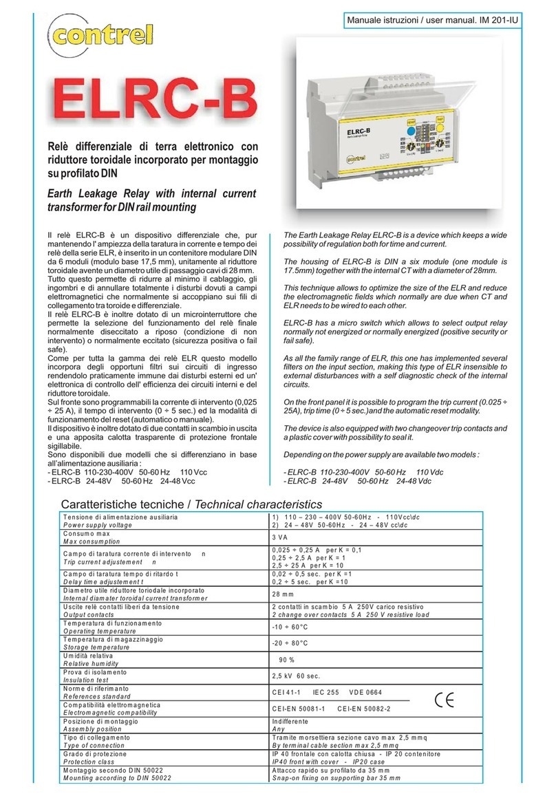
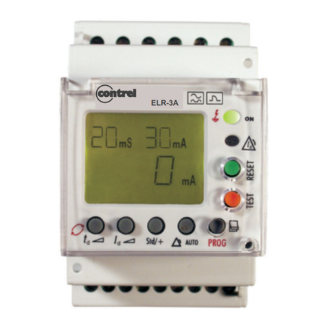
manuals.online logo
Brands
  1. Home
  2. •
  3. Brands
  4. •
  5. Contrel
  6. •
  7. Relay
  8. •
  9. Contrel ELR-4 User manual

Contrel ELR-4 User manual

ELR-2 manuale istruzioni IM208-I v1.01 pag. 1 / 4
MANUALE ISTRUZIONI / INSTRUCTION MANUAL
IM202-IU v1.01
ELR-4 RELÉ DIFFERENZIALE DI TERRA / EARTH LEAKAGE RELAY
ELR-4v
ELR-4Mv
ELR-4o
ELR-4Mo
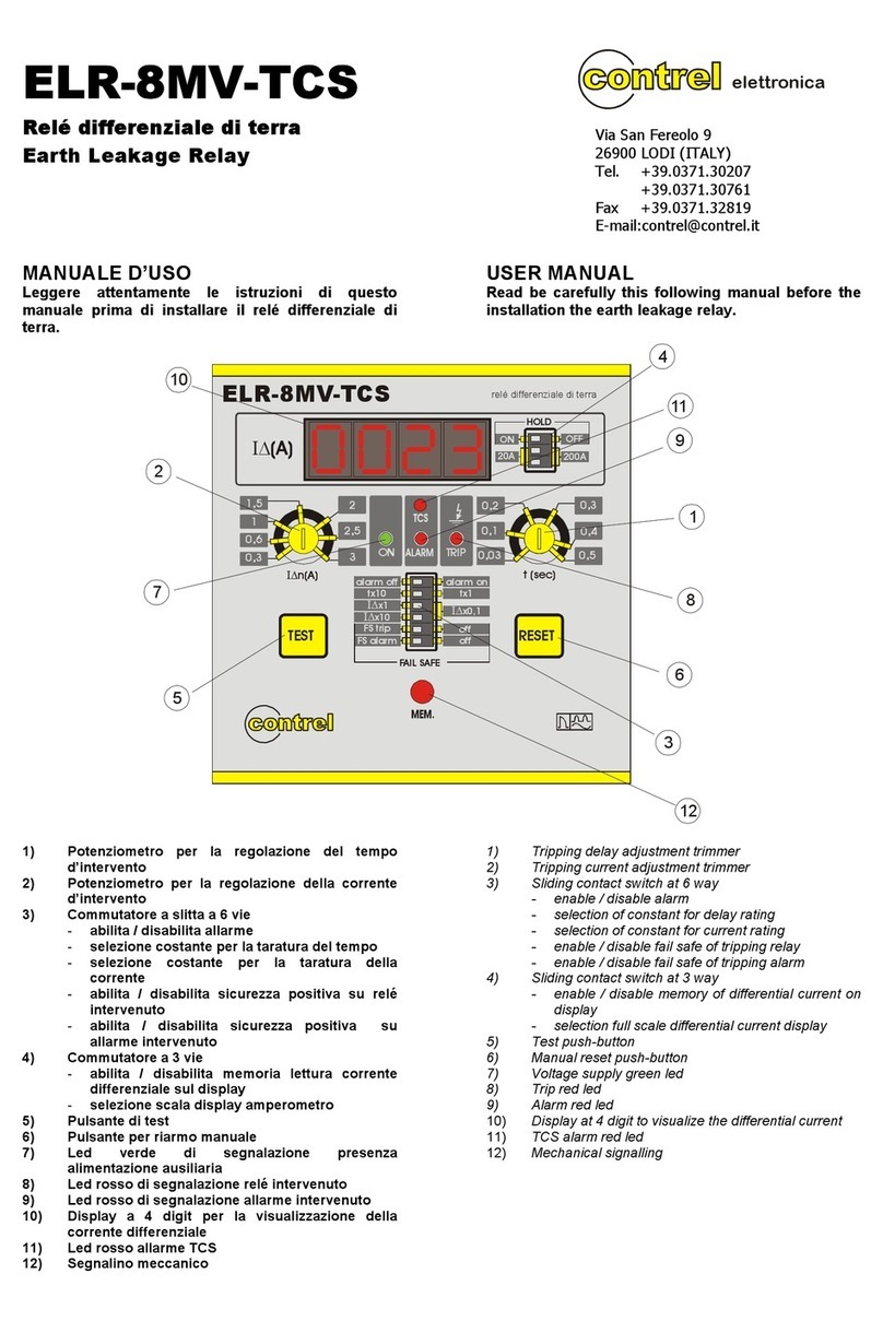
MANUALE D’USO
Leggere attentamente le istruzioni di questo manuale
prima di installare il relé differenziale di terra.
USER’S MANUAL
Read carefully the instructions in this manual before
installing the earth leakage relay.
GENERALITA’
I relè differenziali della serie ELR-4, nonostante le
dimensioni ridotte, conservano tutte le caratteristiche di
base dei relé differenziali della serie ELR. Hanno la
possibilità di essere abbinati a qualsiasi tipo di toroide
della serie CT-1. Disponibili in più versioni in modo da
soddisfare tutte le esigenze riguardanti l’alimentazione
ausiliaria.
Un'importantissima caratteristica del relè è
rappresentata dal controllo permanente dei circuito
toroide-relè differenziale. L'interruzione dello stesso
dovuta a guasto del toroide, rottura del filo di
collegamento, o a guasto di parte della circuiteria
interna, porta all'intervento automatico della protezione.
Tutto questo permette d'individuare immediatamente
l'anomalia, senza dover aspettare il controllo periodico
effettuato con il pulsante di test sull'apparecchio come si
verifica nelle tradizionali esecuzioni.
La vastità di regolazione permette di scegliere molto
facilmente il valore d’intervento in modo tale da
mantenere i valori delle tensioni di contatto al disotto dei
50 V come richiesto dalle norme CEI. Dette regolazioni
permettono, inoltre, di operare una selettività di
intervento sia in corrente che in tempo, quando ci sono
più relé posti sulla linea.
Altra importante caratteristica è l’insensibilità
dell’apparecchio a disturbi esterni in considerazione dei
filtri introdotti sui circuiti di ingresso ed insensibilità alle
correnti continue presenti sulla linea sotto controllo,
secondo quanto richiesto dalle norme VDE.
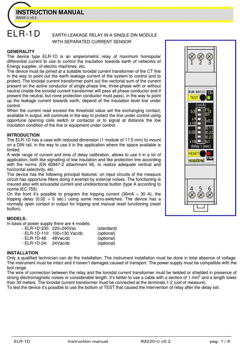
Due sono i test disponibili: quello manuale (pulsante di
test) e quello automatico del collegamento toroide – relé.
MODELLI
Tutti i modelli da incasso hanno dimensioni 48x96 e
presentano le stesse connessioni elettriche.
ELR-4v : versione verticale (v)
ELR-4Mv : versione verticale (v) provvista di
segnalatore meccanico di relé intervenuto
(M)
ELR-4o : versione orizzontale (o)
ELR-4Mo : versione orizzontale (o) provvista di
segnalatore meccanico di relé intervenuto
(M)
GENERALITY
The ELR-4 series, maintain all the basic characteristics
of ELR series, although their reduced dimensions. It can
be coupled to any type of toroid CT-1’s family.
An outstanding characteristic of the present relays, is the
permanent control of the Toroidal - ELR circuit.
Its interruption brings along the immediate trip of the
protection. This allows to identify the anomaly, without
waiting to the periodical control, made with the Test
push button.
Its current and time settings range is very wide. Such a
feature allows to easily choose the tripping current value
in the way that the voltage values are maintained below
50 V, in compliance with CEI standards. It allow, also, to
perform a tripping selectivity, whenever there are more
relay in the same line.
Another important feature is its insensitivity to external
trouble and pulse current with dc components (present
in the line), due to the filters built on the input circuits, as
for the VDE standards.
There are two test available: manual test (test push -
button) and automatic test of toroid – relay circuit.
MODELS
All models have the same dimensions 48x96 and they
have the same ekectric connection.
ELR-4v : vertical version (v)
ELR-4Mv : vertical version (v) with mechanical
signalling of relay tripped (M)
ELR-4o : horizontal version (o)
ELR-4Mo : horizontal version (o) with mechanical
signalling of relay tripped (M)
ELR-2 manuale istruzioni IM208-I v1.01 pag. 2 / 4
INSTALLAZIONE
L’installazione deve essere eseguita da personale
tecnico qualificato e deve avvenire in assenza di
tensione. Assicurarsi che lo strumento sia intatto e non
abbia subito danneggiamenti durante il trasporto.
Accertarsi che le tensioni di alimentazione siano
compatibili con i range consentiti dallo strumento.
Attorcigliare tra loro i fili di collegamento al toroide,
tenerli lontano i cavi di potenza ed in presenza di forti
campi elettromagnetici usare un conduttore schermato.
Ridurre al minimo la distanza tra il toroide ed il relé.
INSTALLATION
Only a qualified technician can do the installation. The
instrument installation must be done in total absence of
voltage. The tool must be intact and it haven’t damages
caused of transport. The power supply must be
compatible with the tool range. Twist together the wires
connecting the relay to the toroid and keep the wires far
from the power cables and use shielded wires if there
are strong magnetics fields. Reduce at the minimum the
length of wires between relay and toroid.
7
8
9
ALIMENTAZIONE
SUPPLY Vaux
Bm
Bm
SCHEMA D’INSERZIONE
CONNECTING DIAGRAM
SCHEMA D’INSERZIONE
/ CONNECTING DIAGRAM
V
ISTA LATO POSTERIORE
/ BACK SIDE VIEW
12031112 789456
ouput relay TRIP
input current
M
A
DE
IN
EU
s.n.
ELR-2 manuale istruzioni IM208-I v1.01 pag. 3 / 4
0.02 ÷ 0.5 sec 0.2 ÷ 5 sec
tx1tx10
t
x1tx10
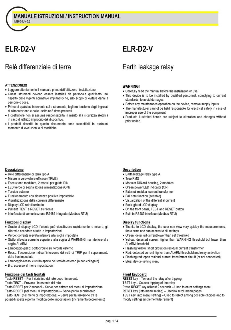
1)Potenziometro per la regolazione del tempo
d’intervento
2)Potenziometro per la regolazione della corrente
d’intervento
3)Commutatore a slitta a 4 vie
-abilita / disabilita riarmo automatico
-selezione costante per la taratura del tempo
-selezione costante per la taratura della corrente
4)Pulsante di test
5)Pulsante per riarmo manuale
6)Led verde di segnalazione presenza alimentazione
ausiliaria
7)Led rosso di segnalazione relé intervenuto
8)Segnalazione meccanica di relé intervenuto
(solo per le versioni M)
1)Tripping delay adjustment trimmer
2)Tripping current adjustment trimmer
3)Sliding contact switch at 4 way
- enable / disable automatic resetting
- selection of constant for delay rating
- selection of constant for current rating
4)Test push-button
5)Manual reset push-button
6)Voltage supply green led
7)Trip red led
8)Mechanical signaling for relay tripped
(only for M versions)
REGOLAZIONE
Regolazione del tempo d’intervento
Le figure indicano le due posizioni del microinterruttore
che definiscono i range dei tempi d’intervento. Il
potenziometro seleziona il tempo all’interno del range
definito dal microinterruttore.
ADJUSTMENT
Tripping delay adjustment
The pictures show the two positions of the switch that it
defines the tripping delay. The trimmer selection the
delay inside the range setted of the switch.
K
2
Regolazione della corrente d’intervento
Le figure indicano le tre posizioni dei microinterruttori
che definiscono i range delle correnti d’intervento. Il
potenziometro seleziona la corrente all’interno del range
definito dal microinterruttore.
Tripping current adjustment
The pictures show the three positions of the switches
that they define the tripping delay. The trimmer selection
the delay inside the range set of the switch.
K
1
Commutatore riarmo automatico o manuale
La figura mostra la posizione del microinterruttore che
permette di attivare il riarmo automatico; nell’altra
posizione il riarmo deve essere fatto manualmente.
Automatic or manual reset
The picture shows the position of switch that allow to
enable automatic reset; in the other position the reset is
manual.
6
5
RESET
TEST
0,25 0,5 1
0,30,40,5
0,20,1
t (sec)
ON
TRIP
MEMORY
TRIP
In(A)
∆
21,52,5
Earth Leakage Relay
ELR-4Mo
RESET
I
∆
nx0,1
tx1
man
I
∆
nx1
I
∆
nx10
tx10
auto
1
27
3
4
TESTRESET
In(A)
∆
2
1,5
2,5
0,25
0,5
10,3
0,4
0,5
0,2
0,1
t
(sec)
I
∆
nx0,1
tx1
man
I
∆
nx1
I
∆
nx10
tx10
auto
RESET
Earth Leaka
g
e Rela
y
ELR-4v
TRIP
ON
8
0.25 ÷ 2.5 A 2.5 ÷ 25 A
0.025 ÷ 0.25 A
I
∆
nx0,1
I
∆
nx1
I
∆
nx10
I
∆
nx0,1
I
∆
nx1
I
∆
nx10
I
∆
nx0,1
I
∆
nx1
I
∆
nx10
man
auto
RESET
ELR-2 manuale istruzioni IM208-I v1.01 pag. 4 / 4
FUNZIONAMENTO
Dopo aver eseguito il cablaggio e regolato lo strumento
in base alle proprie esigenze, si può fornire tensione
all’ELR-4 e verificare l’accensione del led verde di
presenza tensione ausiliaria. L’eventuale intervento del
relé è da attribuire all’interruzione del circuito toroide –
relé o alla presenza di corrente dispersa superiore al
valore settato.
FUNCTIONING
After the connection and the adjustment of tool
depending of the application you can turn on the voltage
supply at the ELR-4 and to verify that the green led of
power supply is on. The eventual trip of relay can
depend by an interruption of the toroid–relay circuit or by
a presence of earth leakage current higher than the
value set.
CARATTERISTICHE TECNICHE / TECHNICAL FEATURES
Tensione d’alimentazione ausiliaria
Supply Voltage
110 Vca/cc 230 – 400 Vca (-15% +10%) oppure 24/48 Vca/cc;
110 Vac/dc 230 – 400 Vac (-15% +10%) or 24/48 Vac/dc;
Frequenza
Frequence
50÷60 Hz
Consumo Max
Max consumption
3 VA
Campo di taratura corrente di scatto
Tripping current range
0.025÷0.25 A (K1=0.1); 0.25÷2.5 A ( K1=1); 2.5÷25 A (K1=10);
Campo di taratura tempo d’intervento
Tripping delay range
0.02÷0.5 s (K2=1); 0.2÷5 s (K2=10);
Contatti in uscita
Output contacts
2 contatti di scambio 5 A 250 V
2 contacts of change 5 A 250 V
Temperatura di funzionamento
Working Temperature
-10 ÷ 60 °C
Temperatura di magazzinaggio
Storage temperature
-20 ÷ 80 °C
Umidità relativa senza condensa
Relative umidità without condensation
<90%
Tipo di collegamento
Type of connection
Morsettiera fissa: sezione cavo 2.5 mm2
Screw terminals for cross section wire 2.5 mm2
Grado di protezione
Protection degree
IP 20 / IP 40 frontale con calotta
IP 20 / IP 40 front face with cover
Prova d’isolamento
Insulation test
CEI 41-1
2.5KV 60 sec
Scarica elettrostatica
Electrostatic discharge
IEC255
CARATTERISTICHE DIMENSIONALI
45
92
R3
55
96
48
123
62 12
9
102
90
Per applicazioni non descritte nel presente manuale riferirsi a specifica documentazione o contattare il servizio di assistenza
NOTE
In ragione delle evoluzione normative e dei prodotti , l’azienda si riserva di modificare in qualunque momento le caratteristiche di prodotto descritte in questa pubblicazione,
che vanno quindi sempre preventivamente verificate.La responsabilità del produttore per danni causati da difetti del prodotto “può essere ridotta o soppressa (…) quando il
danno è provocato congiuntamente da un difetto del prodotto o per colpa del danneggiato o di una persona di cui il danneggiato è responsabile” (Articolo 8, 85/374/CEE)

This manual suits for next models

4

Other Contrel Relay manuals

Contrel ELR-D2-V User manual

Contrel

Contrel ELR-D2-V User manual

Contrel ELR-1D User manual

Contrel

Contrel ELR-1D User manual

Contrel ELR-3A Series User manual

Contrel

Contrel ELR-3A Series User manual

Contrel ELR-51AS User manual

Contrel

Contrel ELR-51AS User manual

Contrel ELR-52AS User manual

Contrel

Contrel ELR-52AS User manual

Contrel ELR-3B User manual

Contrel

Contrel ELR-3B User manual

Contrel ELR-4C User manual

Contrel

Contrel ELR-4C User manual

Contrel ELR-8MV-TCS User manual

Contrel

Contrel ELR-8MV-TCS User manual

Contrel ELR-7 User manual

Contrel

Contrel ELR-7 User manual

Contrel ELR-3B User manual

Contrel

Contrel ELR-3B User manual

Contrel ELRC-B User manual

Contrel

Contrel ELRC-B User manual

Popular Relay manuals by other brands

AutomationDirect RTD180 operating instructions

AutomationDirect

AutomationDirect RTD180 operating instructions

Guard master Minotaur MSR7R manual

Guard master

Guard master Minotaur MSR7R manual

FANOX D30 quick start guide

FANOX

FANOX D30 quick start guide

ABB Relion 615 series Applications manual

ABB

ABB Relion 615 series Applications manual

RELCO RL UN instructions

RELCO

RELCO RL UN instructions

ABB HCB-1 Instruction leaflet

ABB

ABB HCB-1 Instruction leaflet

I-Gard SIGMA 3 manual

I-Gard

I-Gard SIGMA 3 manual

Rockwell Automation Allen-Bradley Guardmaster Minotaur MSR131RTP installation instructions

Rockwell Automation

Rockwell Automation Allen-Bradley Guardmaster Minotaur MSR131RTP installation instructions

Vimar 0170/001 quick start guide

Vimar

Vimar 0170/001 quick start guide

Honeywell NOTIFIER FRM-1 Installation and maintenance instructions

Honeywell

Honeywell NOTIFIER FRM-1 Installation and maintenance instructions

Toshiba GRZ100 B Series instruction manual

Toshiba

Toshiba GRZ100 B Series instruction manual

GMI D5097S instruction manual

GMI

GMI D5097S instruction manual

Victron energy BatteryProtect BP-65 Installation

Victron energy

Victron energy BatteryProtect BP-65 Installation

BURK Technology Plus-X ICRU quick start guide

BURK Technology

BURK Technology Plus-X ICRU quick start guide

BECKWITH ELECTRIC SYNCROCLOSER M-0188A Instruction book

BECKWITH ELECTRIC

BECKWITH ELECTRIC SYNCROCLOSER M-0188A Instruction book

Velleman VM116 manual

Velleman

Velleman VM116 manual

Siemens 3RU7146 Series operating instructions

Siemens

Siemens 3RU7146 Series operating instructions

Omron G9SX-EX401 Series user manual

Omron

Omron G9SX-EX401 Series user manual

manuals.online logo
manuals.online logoBrands
  • About & Mission
  • Contact us
  • Privacy Policy
  • Terms and Conditions

Copyright 2025 Manuals.Online. All Rights Reserved.