manuals.online logo
Brands
  1. Home
  2. •
  3. Brands
  4. •
  5. Contrel
  6. •
  7. Relay
  8. •
  9. Contrel ELR-7 User manual

Contrel ELR-7 User manual

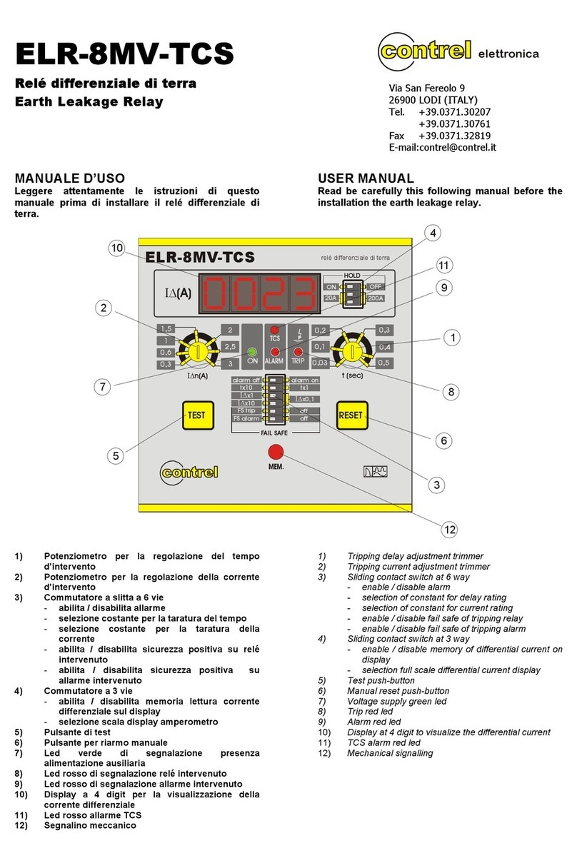
ELR-7 manuale istruzioni / instruction manual IM205-IU v1.6 pag. 1
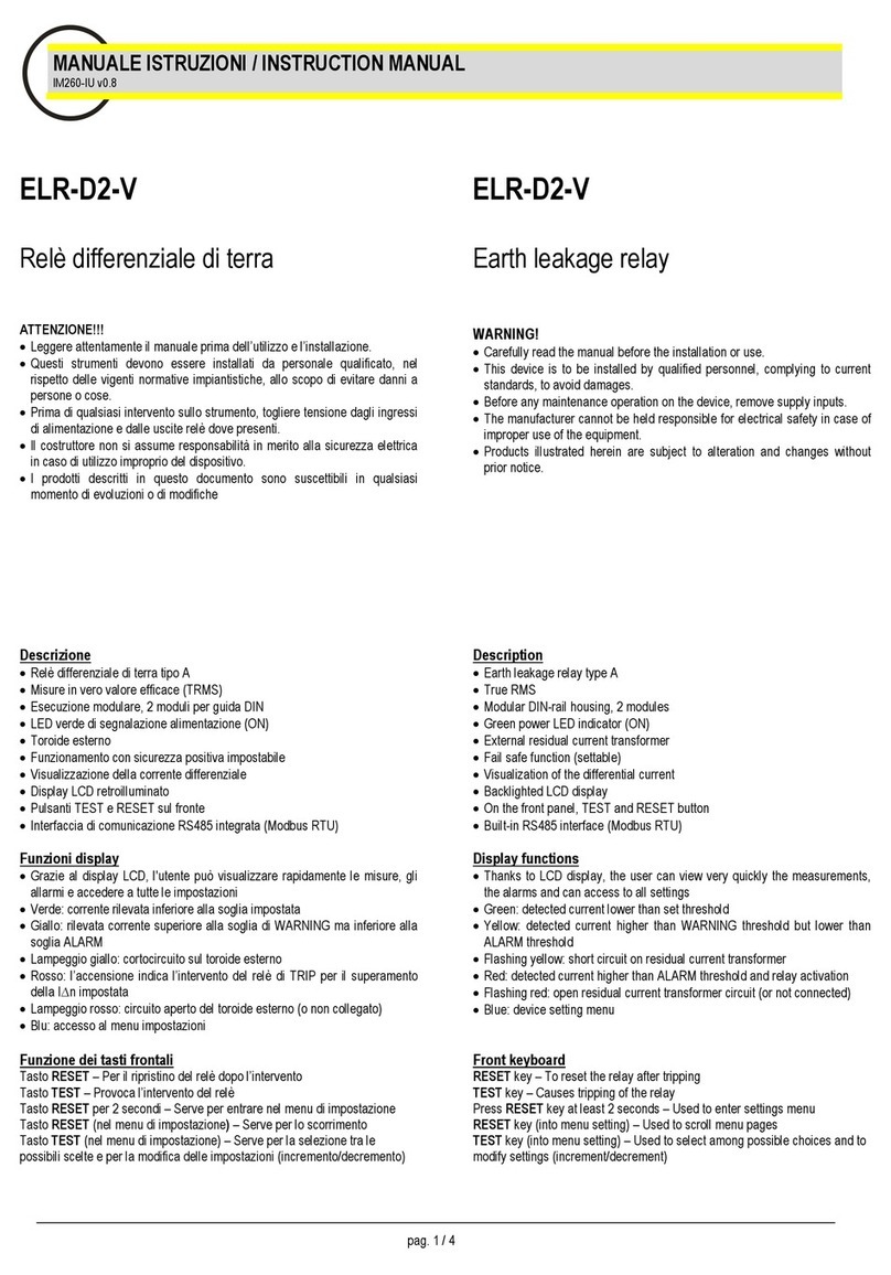
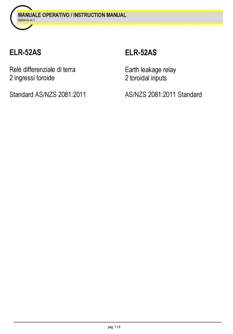
MANUALE ISTRUZIONI / INSTRUCTION MANUAL
IM205-IU v1.6
ELR-7 RELÈ DIFFERENZIALE DI TERRA / EARTH LEAKAGE RELAY
Relè differenziale di terra elettronico
di dimensioni compatte (esecuzione
da incasso DIN 48x48mm) con ampia
regolazione dei parametri di taratura.
Earth Leakage Relay with compact
dimensions (flush mouting DIN
48x48mm) and wide possibility of
parameters regulations.
GENERALITÀ
Il relè ELR-7 è un dispositivo differenziale che, pur
mantenendo l'ampiezza della taratura in corrente e
tempo dei relè della serie ELR e mantenendo le stesse
elevate prestazioni, è inserito in un contenitore per
montaggio da incasso DIN 48x48mm e profondità ridotta
a 72mm comprese le morsettiere.
Tutto questo permette di ridurre al minimo l’ingombro in
quelle applicazioni dove gli spazi sono limitati, come nei
quadri MCC, mantenendo prestazioni adeguate anche
alle installazioni più critiche.Risulta quindi adatto alla
protezione carichi critici, come grandi motori, ecc.
Come per tutta la gamma dei relè ELR questo modello
incorpora degli opportuni filtri sui circuiti di ingresso
rendendolo praticamente immune dai disturbi esterni ed
un'elettronica di controllo permanente dell'efficienza dei
circuiti interni e del riduttore toroidale.
Sul fronte sono programmabili la corrente di intervento
(25mA ÷ 25 A), il tempo di intervento (0,02 ÷ 5 sec.) e la
modalità di funzionamento del reset (automatico o
manuale).
Il relè ELR-7 è dotato di un microinterruttore che
permette la selezione del funzionamento del relè finale
normalmente diseccitato a riposo (condizione di non
intervento) o normalmente eccitato (sicurezza positiva o
fail safe).
Il dispositivo è inoltre dotato di due contatti in scambio
separati in uscita (ad esempio uno per la connessione
alla bobina di apertura dell’interruttore e uno per
segnalazione intervento a distanza), una apposita
calotta trasparente di protezione frontale e comode
morsettiere a vite estraibili.
GENERAL
The earth leakage relay ELR-7 is a device inserted in a
flush mounting DIN 48X48 with an extreme depth of
72mm terminals included, keeping in the same time both
the trip current and delay time adjustment amplitude of
relays series ELR keeping the same high performance.
All that allows to minimize the dimensions in all the
applications where we have place, gaps, like in MCC
electrical panel board.
As for all the ELR series this one has implemented
several filters on the input section, making it insensible
to external disturbances and also a self diagnostic check
of the internal circuits and the external toroidal current
transformer.
For all these reason it is recommended for the protection
of big motors and critical loads.
On the front label it is possible to set the tripping current
(0.025 ÷ 25A), the delay time(0,02 ÷ 5 sec.), the fail safe
and reset modality.
The device is also equipped with two change-over trip
contacts (example the first one for connection to the
shunt trip, the second for remote signalization),and also
with a plastic cover.
Another important feature is the possibility to draw-out
the terminal-board.
MODELLI DISPONIBILI
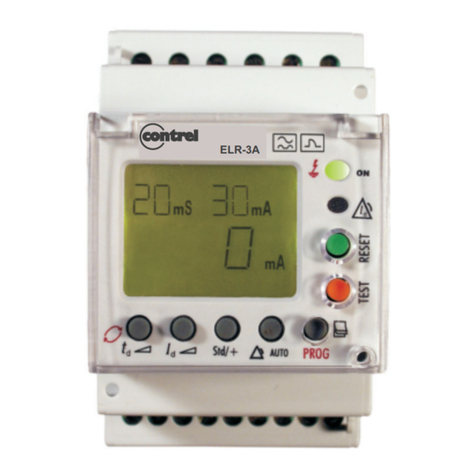
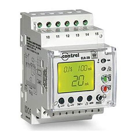
Sono disponibili due modelli che si differenziano in base
all’alimentazione ausiliaria:
- ELR-7 110-230V 50-60 Hz 110 Vcc
- ELR-7 24-48V 50-60 Hz 24-48 Vcc
- ELR-7 220Vcc
EXECUTIONS
According to the auxiliary power supply are available
two executions:
- ELR-7 110-230V 50-60 Hz 110 V dc
- ELR-7 24-48 V 50-60 Hz 24-48V dc
- ELR-7 220Vdc
ELR-7 manuale istruzioni / instruction manual IM205-IU v1.6 pag. 2
OPZIONI
Opzionalmente è possibile richiedere il relè con filtro di
terza armonica incorporato sui circuiti di misura (circa -
22dB a 150Hz, il relè potrà essere applicato solo su
linee a 50-60Hz):
- ELR-7h 110-230V 50-60 Hz 110 Vcc
- ELR-7h 24-48V 50-60 Hz 24-48 Vcc
OPTIONS
On request it is possible to add an additional internal
filter of 3rd harmonics (about -22dB at 150Hz):
- ELR-7h 110-230V 50-60 Hz 110 Vdc
- ELR-7h 24-48V 50-60 Hz 24-48 Vdc
- ELR-7h 220Vdc
- ELR-7h 220Vcc
ACCESSORI
È disponibile su richiesta una speciale calotta frontale
con guarnizione per ottenere una protezione frontale
IP55.
ACCESSORIES
On request is possible to guaranty a IP55 front side
protection using a special plastic cover.
NOTE
Per note tecniche relative all’installazione, regolazione e
per informazioni tecniche relative ai riduttori toroidali
esterni serie CT-1 vedere documentazione relativa
(CAT: C125-IU).
Si ricorda comunque che gli accessori disponibili per
l’intera gamma di relè differenziali ELR sono utilizzabili
anche con questa versione (ad esempio moltiplicatore
esterno, adattatore per connessione a TA, ecc).
Si raccomanda inoltre di utilizzare per il collegamento tra
riduttore toroidale e relè cavetti schermati e/o intrecciati.
NOTE
For all the information regarding installation and the
external current transformers to be connected with the
ELR relays please consult the catalogue C125-IU.
All the accessories used for the ELR series may be used
also for the ELR-7 relay, like the external multiplier CT1-
M type or the adaptor for connection with current
transformer .../5A.
For the connection between toroidal current transformer
and relay must be use twisted pair or shielded cable.
Descrizione – programmazione
Legenda:
1) potenziometro di regolazione
corrente di intervento
2) potenziometro di regolazione
tempo ritardo di intervento
3) microinterruttori di
programmazione:
- a. in posizione 1 riarmo
automatico,
in posizione 0 riarmo
manuale
- b. Scelta costante taratura
costante di moltiplicazione
tempo intervento
in posizione 1 K=10
in posizione 0 K=1
- c,d scelta costante di
moltiplicazione corrente di
intervento
con c,d in posizione 0
K=0,1
con c in posizione 1, d in
posizione 0 K=1
con c,d in posizione 1
K=10
- e in posizione 1 i relè di
uscita saranno diseccitati
a riposo
in posizione 0 i relè di uscita saranno eccitati a
riposo (sicurezza positiva)
4) pulsante di prova
5) pulsante per il riarmo manuale
6) LED verde di segnalazione presenza alimentazione
ausiliaria
7) LED rosso di segnalazione relè intervenuto
8) morsetti di uscita relè finali
9) morsetti per alimentazione ausiliaria e connessione a
riduttore toroidale esterno
Description – setting
Legend:
1) tripping current
adjustement
potentiometer
2) delay adjustement potentiometer
3) dip switch for setup:
- a. in position 1 automatic
reset
in position 0 manual reset
- b. selection of constant for
delay rating
in position 1 K=10
in position 0 K= 1
- c,d selection of constant for
current rating
for c,d in position 0 K=0,1
for c in position 1, d in
position 0 K=1
for c,d in position 1 K=10
- e. in position 1 output relays
normally not energized
in position 0 output relays
normally energized (fail-
safe)
4) test push-button
5) manual reset push-button
6) signalling green LED of auxiliary
voltage supply
7) signalling red LED of tripped relay
8) output relays terminals
9) auxiliary voltage supply terminals and connection to
the external toroidal current transformer
13
5
67
2
9
RESET
AUTO MAN
tx10 tx1
OFF ON
Ix1 x0,1 I
a
b
c
d
e
10
0,25 0,02
0,05
t(sec.)
0,1
0,2
0,5
0,5
ON
TEST
RESET
RESET MAN
OFF ON
FA ILE S AF E
AUTO
t x 10 t x 1
TRIP
Earth Leakage Relay
relè differenziale di terra
In(A)
Inx1
Inx10Inx0,1
0,4
0,3
1,5
2
2,5
1
ELR-7
Ix10
4
12345
7 8 9 10 11 12
9
PANNELLO
FRONTALE
FRONT
PANEL
PANNELLO
POSTERIORE
BACKSIDE
PANEL
ELR-7 manuale istruzioni / instruction manual IM205-IU v1.6 pag. 3
Schema di
connessione
Schema di inserzione con
interruttore con bobina di
apertura a lancio di
corrente e relè finali in
eccitazione all’intervento
(FAIL SAFE OFF) per
l’utilizzo in diseccitazione
(FAIL SAFE ON) collegare
alla BA i morsetti 7 - 8
(contatto NA in condizione
di NON intervento).
Connecting diagram
Connecting diagram with
breaker with opening coil
and output relay NO FAIL
SAFE (OFF) for use output
relay FAIL SAFE (ON)
connected to BA terminals
7 – 8 (contact N.O. in NO
trip condition).
* alimentazione ausiliaria Uaux
morsetti: 1 - 3 = 220-240Vac
morsetti: 2 - 3 = 110-125Vac/cc
oppure
morsetti: 1 - 3 = 48Vac/cc
morsetti: 2 - 3 = 24Vac/cc
oppure
morsetti: 1 - 3 = 220Vcc
*power supply Uaux
terminals: 1 - 3 = 220-240Vac
terminals: 2 - 3 = 110-125Vac/dc
or
terminals: 1 - 3 = 48Vac/dc
terminals: 2 - 3 = 24Vac/dc
or
terminals: 1 - 3 = 220Vdc
Caratteristiche dimensionali Overall dimension
Aux
Terra
Earth
*
ELR-7
CT-1/...
xxxx
45
45
R3
ELR-7
48
48
54
9
44
20 63
calotta protezione
protectioncover
morsettiere
terminals strip
ELR-7 manuale istruzioni / instruction manual IM205-IU v1.6 pag. 4
Caratteristiche tecniche Technical characteristics
Tensione di alimentazione ausiliaria
Power supply voltage
1) 110 – 230V 50-60Hz - 110Vcc\dc
2) 24 – 48V 50-60Hz - 24 – 48V cc\dc
3) 220Vcc/dc
Consumo max
Max consumption 3 VA
Campo di taratura corrente di intervento n
Trip current adjustement n
0,025 ÷ 0,25 A per K = 0,1
0,25 ÷ 2,5 A per K = 1
2,5 ÷ 25 A per K = 10
Campo di taratura tempo di ritardo t
Delay time adjustement t 0,02 ÷ 0,5 sec. per K =1
0,2 ÷ 5 sec. per K =10
Riduttori toroidali esterni e accessori
External toroidal current transformers adn accessories Serie CT-1/… - moltiplicatore taratura, adattatore TA
CT-1/… series - external multiplier settino, CT adapter
Uscite relè contatti liberi da tensione
Output contacts 2 contatti in scambio NA-C-NC 5 A 250V carico resistivo
2 change over contacts NO-C-NC 5 A 250 V resistive load
Temperatura di funzionamento
Operating temperature -10 ÷ 60°C
Temperatura di magazzinaggio
Storage temperature -20 ÷ 80°C
Umidità relativa
Relative humidity 90%
Prova di isolamento
Insulation test 2,5 kV 60 sec.
Norme di riferimanto
References standard CEI 41-1 IEC 255 VDE 0664
Compatibilità elettromagnetica
Electromagnetic compatibility CEI-EN 50081-1 CEI-EN 50082-2
Posizione di montaggio
Assembly position Indifferente
Any
Tipo di collegamento
Type of connection Tramite morsettiera estraibile sezione cavo max 2,5 mmq
By terminal cable section max 2,5 mmq
Grado di protezione
Protection class IP 40 frontale con calotta (opz. IP55) - IP 20 contenitore
IP40 front with cover(opz. IP55) - IP20 case
Montaggio secondo DIN 43700
Mounting according to DIN 43700 Montaggio ad incasso DIN 48x48mm,profondità 72mm
Flush mounting DIN 48x48mm, depth 72mm

This manual suits for next models

1

Other Contrel Relay manuals

Contrel ELR-1D User manual

Contrel

Contrel ELR-1D User manual

Contrel ELR-52AS User manual

Contrel

Contrel ELR-52AS User manual

Contrel ELRC-B User manual

Contrel

Contrel ELRC-B User manual

Contrel ELR-3B User manual

Contrel

Contrel ELR-3B User manual

Contrel ELR-51AS User manual

Contrel

Contrel ELR-51AS User manual

Contrel ELR-4C User manual

Contrel

Contrel ELR-4C User manual

Contrel ELR-3A Series User manual

Contrel

Contrel ELR-3A Series User manual

Contrel ELR-8MV-TCS User manual

Contrel

Contrel ELR-8MV-TCS User manual

Contrel ELR-3B User manual

Contrel

Contrel ELR-3B User manual

Contrel ELR-4 User manual

Contrel

Contrel ELR-4 User manual

Contrel ELR-D2-V User manual

Contrel

Contrel ELR-D2-V User manual

Popular Relay manuals by other brands

Siemens 7SR220 Argus Configuration guide

Siemens

Siemens 7SR220 Argus Configuration guide

Siemens RL Instruction guide

Siemens

Siemens RL Instruction guide

Ampcontrol MEC-1 user manual

Ampcontrol

Ampcontrol MEC-1 user manual

Eaton Cutler-Hammer D64RP18 instruction manual

Eaton

Eaton Cutler-Hammer D64RP18 instruction manual

ZIEHL TR 800 Web operating manual

ZIEHL

ZIEHL TR 800 Web operating manual

Siemens 3RU2116 8K Series operating instructions

Siemens

Siemens 3RU2116 8K Series operating instructions

Idem SEU-1 instructions

Idem

Idem SEU-1 instructions

ZIEHL MS220KA operating manual

ZIEHL

ZIEHL MS220KA operating manual

Pilz PNOZ XV1P operating instructions

Pilz

Pilz PNOZ XV1P operating instructions

Aqara T1 quick start guide

Aqara

Aqara T1 quick start guide

Sel 411L instruction manual

Sel

Sel 411L instruction manual

Pilz PNOZ X7P 24 V DC/AC operating instructions

Pilz

Pilz PNOZ X7P 24 V DC/AC operating instructions

Basler BE1-32R instruction manual

Basler

Basler BE1-32R instruction manual

jablotron AC-83 manual

jablotron

jablotron AC-83 manual

Pilz PNOZ X2.1VP operating manual

Pilz

Pilz PNOZ X2.1VP operating manual

AMX AXC-SAV Dimensional drawing

AMX

AMX AXC-SAV Dimensional drawing

EUCHNER ESM-2H2 Series operating instructions

EUCHNER

EUCHNER ESM-2H2 Series operating instructions

Zamel EXTA PCP-06 quick start guide

Zamel

Zamel EXTA PCP-06 quick start guide

manuals.online logo
manuals.online logoBrands
  • About & Mission
  • Contact us
  • Privacy Policy
  • Terms and Conditions

Copyright 2025 Manuals.Online. All Rights Reserved.