manuals.online logo
Brands
  1. Home
  2. •
  3. Brands
  4. •
  5. Contro l4
  6. •
  7. Dimmer
  8. •
  9. Contro l4 C4-FPD120 User manual

Contro l4 C4-FPD120 User manual

™
Minimum Load (without neutral)
Incandescent (Tungsten) 25W
Halogen 25W
Fluorescent* N/A
Compact Fluorescent (CFL)* N/A
LED* N/A
Environmental
Operational Temperature 32˚ F - 104˚ F (0˚ C - 40˚ C)
All load ratings are based on an ambient
temperature of 25˚ C.
Humidity 5% to 95% non-condensing
Storage -4˚ F - 158˚ F (-20˚ C - 70˚ C)
Miscellaneous
Control Communications ZigBee, IEEE 802.15.4, 2.4 GHz, 15-channel
spread spectrum radio
Wallbox Volume 5.75 cubic inches
Weight 0.12 lb. (0.05 kg)
Shipping Weight 0.18 lb. (0.08 kg)
* NOTES:
(1) The maximum and minimum load requirements for fluorescent, CFL
and LED loads can vary greatly depending upon the specific fixture and/
or bulb being used. At higher wattages, these load types have significant
in-rush current which can trip the protection circuitry on the device. At
low wattages, some CFL and LED loads will not be able to completely
shut o.
(2) In both cases, the quality and performance of these load types varies
greatly from manufacturer to manufacturer. When using these load types,
we recommend testing in advance. If problems are found, simply changing
to a dierent bulb manufacturer may solve the problem.
(3) Additionally, we do not recommend the use of fluorescent, CFL, or
LED loads without a neutral wire connected to the dimmer due to the
capacitive nature of these load types.
Warnings and Considerations
WARNING! Turn OFF electrical power before installing or servicing this
product. Improper use or installation can cause SERIOUS INJURY, DEATH
or LOSS/DAMAGE OF PROPERTY.
ATTENTION! Coupez l’alimentation électrique avant d’installer ou de
réparer ce produit. Une mauvaise installation ou utilisation peut entraîner
des blessures graves, décès ou perte / dommages à la propriété.
WARNING! This device must be protected by a circuit breaker (20A max).
ATTENTION! Cet appareil doit être protégé par un disjoncteur (20A max.)
WARNING! Ground this device in accordance with the National Electric
Code (NEC) requirements. DO NOT rely solely upon the yoke plate’s
contact with a metal wallbox for adequate grounding. Use the device’s
ground wire to make a secure connection to the safety ground of the
electrical system.
ATTENTION! Cet appareil doit être en conformité avec le Code national
de l’électricité (NEC). Ne comptez pas uniquement au contact de la
plaque avant avec un boîtier mural métallique pour la mise à la terre
adéquate. Utilisez cet appareil à la terre de l’appareil pour établir une
connexion sécurisée au système électrique.
IMPORTANT! This device must be installed by a licensed electrician in
accordance with all national and local electrical codes.
IMPORTANT! If you are unsure about any part of these instructions,
consult a qualified electrician.
Supported Model
đŏ C4-FPD120 Forward Phase Dimmer
Introduction
The Control4® Forward Phase Dimmer operates independently or as part of a
Control4 home automation system. It installs in a standard wall box using typical
wiring standards and communicates to the Control4 system using a wireless
connection.
Box Contents
đŏ Forward Phase Dimmer
đŏ Wire Nuts
đŏ Warranty Card
đŏ +.3. ŏ$/!ŏ%))!.ŏ*/0((0%+*ŏ1% ! (this document)
Specifications and Supported Load Types
The specifications are described below.
Model Number C4-FPD120-xx
Power Requirements 120 VAC +/-10%, 50/60 Hz
This device can function with or without a
neutral AC connection depending on load type.
See load types and wiring diagrams below.
When wired without a neutral, loads may
appear dimmer.
Power Consumption 450mW
Load Types and Ratings
Supported Load Types Incandescent; Halogen; Magnetic (Iron Core,
Inductive) Low Voltage (MLV) transformers;
Forward Phase Dimmable Fluorescents,
Compact Fluorescents, and LEDs.
Maximum Load 1 Gang 2 Gang 3+ Gang
Incandescent (Tungsten) 1000W 800W 600W
Halogen 1000W 800W 600W
Fluorescent* 500W 500W 500W
Compact Fluorescent (CFL)* 500W 500W 500W
LED* 200W 200W 200W
Minimum Load (with neutral)
Incandescent (Tungsten) 4.5W
Halogen 4.5W
Fluorescent* 4.5W
Compact Fluorescent (CFL)* 4.5W
LED* 4.5W
Forward Phase
Dimmer
Installation Guide
IMPORTANT! Use this device only with copper or copper-clad wire. Do
not use aluminum wiring. This product has not been approved for use with
aluminum wiring.
IMPORTANT! To reduce the risk of overheating and possible damage
to other equipment, do not install to control a receptacle or a motor
operated appliance.
IMPORTANT! This product generates heat during normal operation.
IMPORTANT! Using this product in a manner other than outlined in this
document voids your warranty. Further, Control4 is NOT liable for any
damage incurred with the misuse of this product. See “Troubleshooting.”
IMPORTANT! Do NOT use a power screwdriver to install this device. If you
do, you may overtighten the screws and strip them. Also, overtightening
the screws may interfere with proper button operation.
IMPORTANT! This is an electronic device with intricate components.
Handle and install with care!
Installation Instructions
1 Ensure that the location and intended use meet the following criteria:
đŏ Do not exceed the load capacity requirements of the dimmer. In multi-
gang installations, a reduction of the dimmers’ capacity is required to allow
the dimmers to be installed side-by-side. Refer to the load ratings in the
specifications above for details.
đŏ Install in accordance with all national and local electrical codes.
đŏ The range and performance of the wireless control system is highly
dependent on the following: (1) distance between devices; (2) layout of the
home; (3) walls separating devices; and (4) electrical equipment located near
devices.
2 If installing in a multi-gang scenario, use pliers to remove the inner-side
breakaway tabs. Bend each tab forward, and then back and forth until it
breaks o. Remove the inner-side tabs ONLY on any device side that will
be adjacent to another device. DO NOT remove tabs on any side that will
become the outer side of a group of devices. Handle the device with care
after removing the tabs, as the broken edge can be sharp.
3 Turn o the local electrical power by either switching o the circuit breaker or
removing the fuse from the fuse box. To ensure the wires do NOT have power
running to them, use an inductive voltage detector.
NOTE: The wallbox wiring shown in this document is an example. Your
wire colors and functions may dier. If you are not sure which wires
are the Hot, Neutral, Load, Traveler, and Ground wires, have a trained
electrician perform the installation.
4 Prepare each wire. Wire insulation should be stripped back 5/8 of an inch
from the wire end (see Figure 1).
Figure 1. Strip Wire Insulation
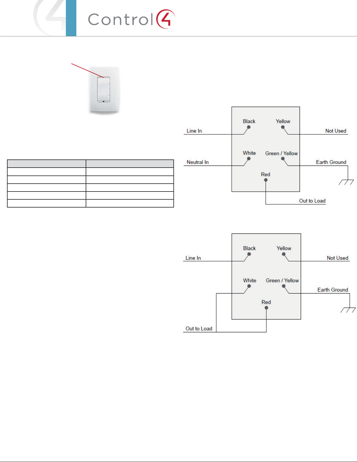
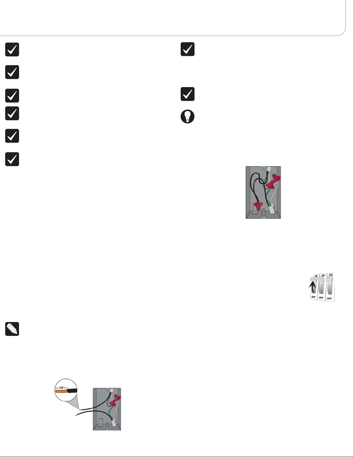
5 Identify your wiring application, and then see the appropriate wiring diagram
in the “Sample Wiring Configurations” section below.
IMPORTANT! Not grounding this product, as described in the “Warnings
and Considerations” section, may result in an installation less immune to
damage caused by electrical disturbances, such as ESD or lightning, and
may void the warranty.
6 Identify and connect the dimmer wires to the wallbox wires using the wire
nuts.
IMPORTANT! The yellow wire is not a traditional traveler. It cannot directly
power a lighting load. It must be used only to connect to a Control4
Auxiliary Keypad. See “Sample Wiring Configurations.”
TIP: If you are using a Control4 push-on (screwless) faceplate in a multi-
gang installation, attach the black faceplate sub-plate to all of the devices
that will be installed into the wallbox prior to attaching the devices to the
wallbox. This will help ensure that all the devices are properly aligned and
on the same plane after installation.
7 Fit the wires back into the wallbox. Bend the wires in a zigzag pattern so that
they easily fold into the wallbox (Figure 2).
Figure 2. Bend the Wires
8 Align the dimmer to the wallbox (the load rating label should be at the
bottom) and fasten it with screws. Tighten the screws until the back side of
the yoke plate is even with the wall surface, but no further. Overtightening can
warp the dimmer and cause mechanical malfunction.
9 Install the Control4 Faceplate following the instructions in the Faceplate
Installation Guide or attach a standard Decora style faceplate.
10 Turn ON power at the circuit breaker or replace the fuse
from the fuse box.
Operation and Configuration
On initial power up, all status LEDs on the dimmer will illuminate green indicating
that the device has power. To set up this dimmer for use with a Control4 system,
refer to the Composer Pro User Guide.
To operate this dimmer as a stand-alone device:
đŏ Click the top button to turn the light on.
đŏ Click the bottom button to turn the light o.
đŏ Press and hold the top button to ramp the light up. Release the button at the
desired light level.
đŏ Press and hold the bottom button to fade the light down. Release the button
at the desired light level.
Air Gap Switch
During routine lamp replacement, remove power from the lamp by engaging the
air gap mechanism. To engage, press on the right side of the top actuator bar until
the left side pops out. All LEDs on the dimmer will turn o and the dimmer will no
longer control the light when the air gap mechanism has been engaged. To return
power to the dimmer and lamp, press on the left side of the top actuator bar until
it snaps back into place.
™
Figure 3. Dimmer Actuator Bar
Button Tap Sequences
The button tap sequences are defined in the table below. Button tap sequences
that require a single (1) button should use the top-most button installed on the
dimmer.
Function Button Sequence
Identify 4
ZigBee Channel 7
Reboot 15
Factory Reset 9-4-9
Leave Mesh and Reset 13-4-13
Troubleshooting
If the light does not turn on:
đŏ Ensure at least one LED on the face of the dimmer is lit.
đŏ Ensure the light bulb is not burned out and is screwed in tightly.
đŏ Ensure that the circuit breaker is not turned OFF or tripped.
đŏ Check for proper wiring (see “Sample Wiring Configurations”).
đŏ For help on the installation or operation of this product, email or call the
Control4 Technical Support Center. Please provide your exact model number.
Contact support@control4.com or see the web site www.control4.com.
Care and Cleaning
đŏ Do NOT paint the dimmer or its wall plate.
đŏ Do NOT use any chemical cleaners to clean the dimmer.
đŏ Clean surface of the dimmer with a soft damp cloth as needed.
Regulatory/Safety Information
To review Regulatory information for your particular Control4 products, see
the information located on the Control4 website at: http://www.control4.com/
regulatory/.
Patent Information
Applicable patents are available at http://www.control4.com/legal/patents.
Warranty
For complete warranty information, including details on consumer legal rights as
well as warranty exclusions, review the Warranty card or visit www.control4.com/
warranty.
About this Document
Part Number: 200-00307, Rev C 7/30/2013 BN
Sample Wiring Configurations
Figure 4. Single Device Location, With Neutral Connection
Figure 5. Single Device Location, Without Neutral Connection
Actuator Bar
Figure 6. Multiple Device Location Using Auxiliary Keypad, With Neutral Connection
Figure 7. Multiple Device Location with Auxiliary Keypad, Without Neutral Connection
Figure 8. Multiple Device Location Using Configurable Keypad, Neutral Required
Copyright ©2013 Control4. . All rights reserved. Control4, the Control4 logo, the Control4 iQ logo and the Control4 certified logo are registered trademarks or trademarks of Control4 Corporation in
the United States and/or other countries. All other names and brands may be claimed as the property of their respective owners Pricing and specifications are subject to change without notice

Other Contro l4 Dimmer manuals

Contro l4 C4-DIN-8APD-E Quick guide

Contro l4

Contro l4 C4-DIN-8APD-E Quick guide

Contro l4 C4-KD120 Series User manual

Contro l4

Contro l4 C4-KD120 Series User manual

Contro l4 C4-DIN-8FPD-E Quick guide

Contro l4

Contro l4 C4-DIN-8FPD-E Quick guide

Contro l4 Wireless Outlet Dimmer User manual

Contro l4

Contro l4 Wireless Outlet Dimmer User manual

Contro l4 C4-TV120277 User manual

Contro l4

Contro l4 C4-TV120277 User manual

Contro l4 C4-APD120 User manual

Contro l4

Contro l4 C4-APD120 User manual

Contro l4 8-Channel User manual

Contro l4

Contro l4 8-Channel User manual

Contro l4 C4-KD120 User manual

Contro l4

Contro l4 C4-KD120 User manual

Contro l4 LDZ-101 User manual

Contro l4

Contro l4 LDZ-101 User manual

Popular Dimmer manuals by other brands

Lightronics AS-62D owner's manual

Lightronics

Lightronics AS-62D owner's manual

Newlab L458MC04T1A01 user manual

Newlab

Newlab L458MC04T1A01 user manual

Ekinex EK-GD2-TP-1-HV Applications manual

Ekinex

Ekinex EK-GD2-TP-1-HV Applications manual

Sunricher SR-2304B manual

Sunricher

Sunricher SR-2304B manual

Savi QORALUX installation guide

Savi

Savi QORALUX installation guide

Leprecon ULD-340DMX-HP user manual

Leprecon

Leprecon ULD-340DMX-HP user manual

Lite-Puter DX-610 user manual

Lite-Puter

Lite-Puter DX-610 user manual

Sunricher SR-2805RCCT quick start guide

Sunricher

Sunricher SR-2805RCCT quick start guide

AMX RDM-3FDB TRIPLE FDB MODULE Installation sheet

AMX

AMX RDM-3FDB TRIPLE FDB MODULE Installation sheet

Vimar Eikon 20135.1.120 manual

Vimar

Vimar Eikon 20135.1.120 manual

Lutron Electronics QOTO Q-600P quick start guide

Lutron Electronics

Lutron Electronics QOTO Q-600P quick start guide

Leviton i Series e user guide

Leviton

Leviton i Series e user guide

SkylinkHome PR-318 instruction manual

SkylinkHome

SkylinkHome PR-318 instruction manual

Sunricher SR-2805RGB quick start guide

Sunricher

Sunricher SR-2805RGB quick start guide

Botex DPX-620III user manual

Botex

Botex DPX-620III user manual

URC VL-9534-MD-X installation instructions

URC

URC VL-9534-MD-X installation instructions

QOLSYS IQ Dimmer quick start guide

QOLSYS

QOLSYS IQ Dimmer quick start guide

INSTEON 2334-232 quick start guide

INSTEON

INSTEON 2334-232 quick start guide

manuals.online logo
manuals.online logoBrands
  • About & Mission
  • Contact us
  • Privacy Policy
  • Terms and Conditions

Copyright 2025 Manuals.Online. All Rights Reserved.