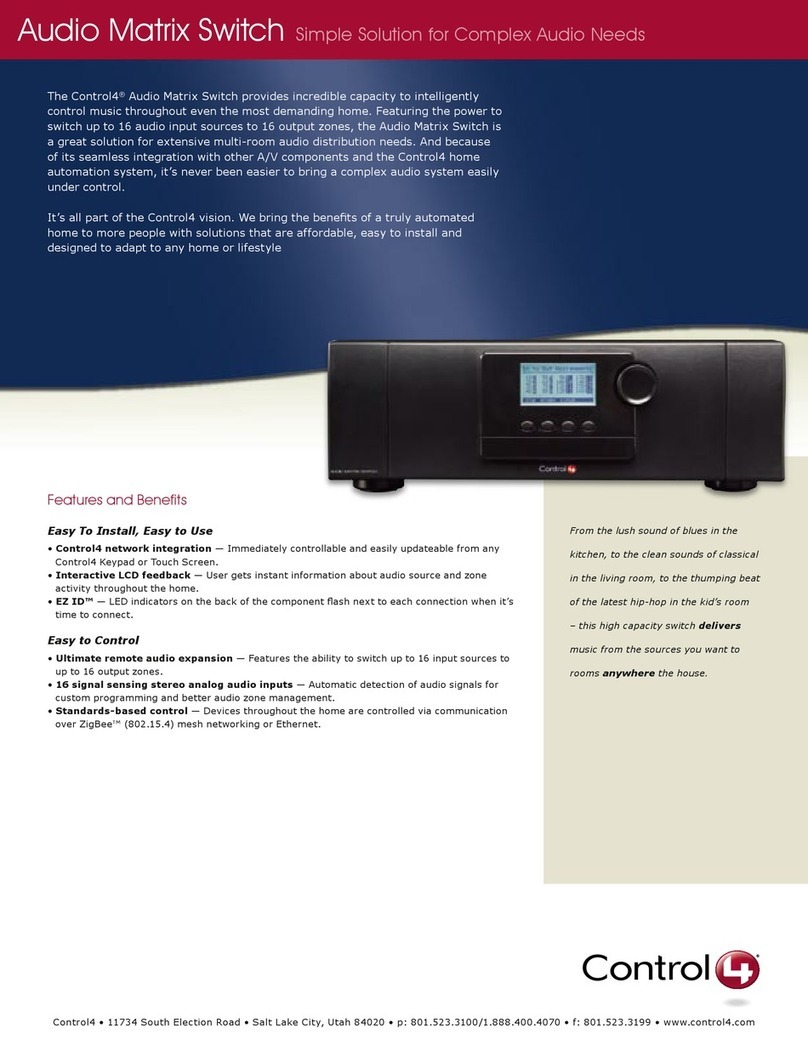
Audio Matrix Switch
Installation and Setup Guide
Supported Models
• C4-16S2-E-B Control4® Audio Matrix Switch
Important Safety Instructions
Box Contents
• Control4 Audio Matrix Switch
• IEC Power Cord
• AudioMatrixSwitchInstallationandSetupGuide (this document)
Front Display— For displaying or set-
ting audio switch settings and navigating
system menus.
Buttons— For choosing options or
menus displayed in the front panel user
interface.
Select Dial— For scrolling through and
selecting screen elements or options
displayed in the LCD.
1
2
3
Inputs
# of Channels 16 L/R Stereo Pairs
Input Connectors RCA Jacks
Input Impedance 10 kW typical
Nominal Input Level -14 dBV
Maximum Input Level +4 dBV
Outputs
# of Channels 16 L/R Stereo Pairs
Output Connectors RCA Jacks
Output Impedance 50 W typical
Nominal Output Level -14 dBV
Maximum Output Level +4 dBV
Zone (Output) Control
Available Gain Mute (-75 dB) to -40 to +8 dB
Treble -12 to +12 dB, 2 dB steps, High Shelving EQ
Bass -12 to +12 dB, 2 dB steps, Low Shelving EQ
Balance L/R
ProductSpecications
WARNING! Do not expose the apparatus to dripping or splashing. Do not place
objectslledwithliquidsneartheapparatus.
AVERTISSEMENT ! N’exposez pas l’appareil à l’égoutture ou à l’éclaboussement.
Neplacezpaslesobjetsremplisdeliquidesprèsdel’appareil.
WARNING! Setzen Sie den Apparat nicht Bratenfett oder dem Spritzen aus. Setzen
Sie nicht die Gegenstände, die mit Flüssigkeiten nahe dem Apparat gefüllt werden.
WARNING! Toreducetheriskofreorelectricalshock,donotexposethisapparatus
to rain or moisture.
AVERTISSEMENT !Pourréduirelerisquedufeuoudechocélectrique,n’exposez
pas cet appareil à la pluie ou à l’humidité.
WARNING! Um die Gefahr des Feuers oder des elektrischen Schlages zu verringern,
setzen Sie diesen Apparat nicht Regen oder Feuchtigkeit aus.
IMPORTANT! Using this product in a manner other than outlined in this document
voids your warranty. Further, Control4 is NOT liable for any damage incurred with the
misuse of this product. See “Limited 2 Year Warranty.”
IMPORTANT !Employerceproduitenquelquesorteautrequedécritdanscedocu-
ment vide votre garantie. De plus, Control4 n’est pas responsable d’aucun dommage
encouruavecl’abusdeceproduit.Voyezque«alimitélagarantiede2ans.»
WICHTIG! Das Verwenden dieses Produktes in gewissem Sinne anders als umrissen
in diesem Dokument hebt Ihre Garantie auf. Weiter ist Control4 NICHT für irgendeine
Beschädigung verantwortlich, die mit der Fehlanwendung dieses Produktes genom-
men wird. Sehen Sie, daß „begrenzte eine 2 Jahr-Garantie.“
WARNING! EquipmentmustbeconnectedtoaMainssocketoutletwithaprotective
earthing connection.
ADVERTISSEMENT!L’équipementdoitêtrereliéàunesortiededouilledeforcesà
un raccordement de mise à la terre protecteur.
WARNUNG! Ausrüstung muss an einen Hauptleitungseinfaßungsanschluß mit einem
schützenden Erdunganschluß angeschlossen werden.
IMPORTANT! To avoid generating excessive heat, do not stack Speaker Points on
topofeachotherorotherequipment.
IMPORTANT ! Pour éviter de produire de la chaleur excessive, n’empilez pas les
pointsdehaut-parleursurl’unl’autreoutoutautreéquipement.
WICHTIG! Um übermäßige Hitze zu erzeugen zu vermeiden, stapeln Sie Lautsprech-
er-Punkte nicht auf einander oder andere Ausrüstung.
Features and Benefits
• Switches up to 16 input sources to up to 16 simultaneous output zones.
• Adjustable gain, treble, bass, and balance for each zone
• Audio sensing on inputs
• Device chassis is three standard rack units (RU) tall and rack mountable conforming to
EIA 19” rack standards (5.25” x 17.34” x 14”)
• Communicates with control devices via Ethernet 10/100 port and ZigBee (a wireless
standard for mesh-networking).
Backlighting feature turns on with any button push or Select Dial push and stays lit for a
preset time (default is 30 seconds).
Front and Rear Panel Description
Front Panel
Back Panel
1 2 3
1 2 3 4
Power Plug Port — For standard IEC cord (included). Supports universal AC input
(100-240 VAC 50/60 Hz).
Ethernet — Ethernet RJ-45 port for a 10/100 MB Ethernet connection.
Audio In (Left-Right Pairs) 1-16 — RCA jacks for stereo channel input for up to 16
stereo analog sources.
Audio Out (Left-Right Pairs) 1-16 — RCA jacks for stereo channel line output for up to
16ampliers.
1
2
3
4
Set Up the Audio Matrix Switch
At the In to Out Assignments screen, press the Network button.
OntheNetworkCongurationscreen,chooseanEthernetorZigBeenetworkbyrotat-
ing and pressing the Select dial.
1
2
Press the Select dial to enter edit mode.
Press the Down or Up button (or rotate the Select dial) to choose Static IP.
a
b
IMPORTANT! When making logical connections in Composer, identify the device as
the network type (Ethernet or Zigbee) that you choose on the device network con-
guration.Toavoidunexpectedbehavior,donotidentifythedeviceasbothnetwork
types.
IMPORTANT! Enétablissantlesrapportslogiquesdanslecompositeur,identiez
le dispositif comme type de réseau (Ethernet ou Zigbee) ce vous choisissent sur la
congurationréseaudedispositif.Pouréviterlecomportementinattendu,n’identiez
pasledispositifentantquelesdeuxtypesderéseau.
WICHTIG! WennSielogischeBeziehungenimKomponistenherstellen,identizie-
renen Sie die Vorrichtung als die Netzart (Ethernet oder Zigbee) diese Sie wählen
aufderVorrichtungsNetzwerkkonguration.UmunerwartetesVerhaltenzuvermei-
den,identizierenenSiedieVorrichtungnichtalsbeideNetzarten.
Input Power Requirements
Voltage 100-240V~
Frequency 50/60 Hz
Amps 0.12/0.06 Amps
Watts 14.4 Watts
Source Inputs
Each of the 16 signal sensing analog audio inputs (the RCA style ports) is labeled
1-16 for each individual source.
Audio Outputs
The system automatically creates generic source names displayed in the front of the device.
To change these names, you must update your system using Composer Pro. For more
information, refer to the documentation that shipped with your Control4 Controller or contact
your Control4 Installer or Reseller.
Front Display
The best method of initially setting up system routing for the Audio Matrix Switch is using
Composer Pro. You can also make adjustments from the front display.
The front display lets you set or change audio source routing and change zone settings for
volume, bass, treble, and mute. The display also shows the current source and zone activity.
ThisdeviceoperatesaspartoftheControl4homesystem,whichrequiresphysicalandlogi-
cal connections to function as designed.
Essential setup tasks include:
1. Connect input and output devices
2. Connect to the network and power
3. Set up logical connections
4. StaticIPmodications
Thissectiondescribes,ingeneralterms,howtosetupphysicalconnectionsrequiredforthe
AudioMatrixSwitchandallassociateddevices.Refertoanydevice-specicdocumentation
for additional installation instructions.
Tosetupthelogicalconnectionsrequired,refertoControl4ComposerProUserGuide for
details.
Connect Input and Output Devices
1. Connect audio source devices (such as CD Changers or players, tuners, iPods, or
tape players) you want included in the system to the Audio In jacks.
2. ConnectampliersorampliedspeakersasneededtotheAudioOutjacks.
Connect to the Network and Power
1. If you are using an Ethernet connection for the Audio Matrix Switch, plug the data
cable from the home network connection into the Audio Matrix Switch RJ-45 port
(labeled Ethernet) and the network port in your wall or at the network hub or switch.
2. Connect the power cord provided into the back of the Audio Matrix Switch and to the
power outlet. When the power cord is connected, the Audio Matrix Switch should
power up.
Set Up Logical Connections
Physicalandlogicalconnectionsarerequiredinordertocontrol,navigate,andusethe
Audio Matrix Switch as designed.
So far you have set up the physical connections for the Control4 Audio Matrix Switch. To
complete the logical setup, trained installers must use a PC connected (and with Control4
Composer software installed) to the home network. If you are a trained Control4 installer,
refertotheControl4ComposerHelple.
NetworkConguration
Tosetthenetworkconguration:
If the switch is set to use a ZigBee network, the EUID, Gateway, and ZigBee channel
number are displayed. This screen has these menu options:
• Identify: When identifying the switch in Composer, press this button.
• Back:ReturnstotheNetworkCongurationscreen.
If the switch is set to use an Ethernet network, the MAC address, method of obtaining a
network IP address, the device’s IP address, Subnet Mask, and Gateway are displayed.
The Audio Matrix Switch, by default, uses DHCP to obtain a network IP address.
3
4
IfthelocalareanetworkdoesnotsupportDHCP,youcanconguretheswitchtousea
Static IP address instead:
Press OK (or press the Select dial).
Press Save (or press the Select dial).
a
b
EdittheIP,Mask,andGatewayeldsfortheStaticIPnetwork:UsetheSelectdialto
select a line, and then press the dial.
5
1. Read and keep these instructions.
2. Heed all warnings and follow all instructions for this product in this and other Con-
trol4® documents included with or related to this product.
3. Improper use of this product may result in potential electric shock.
4. Do not use this product near water.
5. Neverspillliquidofanykindonthisproduct.
6. Cleanthisproductonlywithadampordrycloth.Donotuseliquidcleanersoraerosol
cleaners to clean the product.
7. Install this product according to the manufacturer’s instructions.
8. Install this product according to the National Electrical Code ANSI/NFPA 70 and the
prevailinglocalcodesandrequirements.
9. This product should be operated with the type of power indicated on the marked label.
If you are not sure of the type of power available, consult your Control4 dealer or local
power company.
10. Slots and openings on a cabinet rack, and components used with this product are pro-
vided for ventilation, reliable operation, and protection from overheating of the product.
These slots and openings must not be blocked or covered.
11. This product should never be placed near or over a radiator or heat register, or in a
built-in installation unless proper ventilation is provided.
12. Never push objects of any kind into this product through cabinet slots because they
maytouchdangerousvoltagepointsorshortoutpartsthatcouldresultinareor
electric shock.
13. Only use the attachments and accessories included with this product or recommended
by Control4.
14. Do not allow anything to rest on the power cord. Do not install or place this product
where people will walk on the cord.
15. Do not use extension cords with any products in a Control4 system.
16. If applicable, unplug this product during lightning storms or when unused for long
periods of time.
17. Donotexceedthemaximumwiresize(ifspecied)inthisguide.
18. Thisproductmustbeinstalledbyqualiedprofessionalsonly.
19. Do not attempt to service this product yourself except as noted in this guide. Opening
or removing covers of internal components may expose you to dangerous voltage
points or other risks.
20. Referallservicingtoqualiedservicepersonnel.Servicingisrequiredwhentheap-
paratus has been damaged or frayed in any way; for example, a power-supply cord or
plugisdamaged,liquidhasbeenspilledorobjectshavefallenintothisproduct,this
product has been exposed to rain or moisture, this product does not operate normally,
or this product has been dropped.
