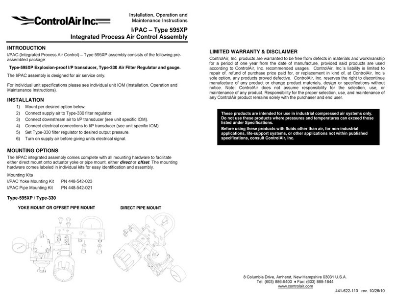
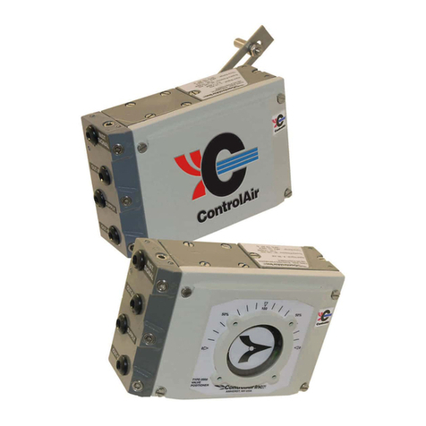
controlair 500 Series Manual

1.0 Description & Installation 2
2.0 Operation 3
3.0 Maintenance 5
4.0 Troubleshooting 5
5.0 Warranty 5
Pilot Pressure
Atmospheric Pressure
Supply Pressure
Output Pressure
441-622-015 Type 500X Page 1
Electropneumatic Transducer (I/P, E/P)
Installation, Operation and
Maintenance Instructions
Type 500X
Ordering Information
Type 500X I/P Transducers
Output Range
Part Number Input psi bar Impedance
<EED66 5DAEF?6 0D" ECADEC( "EF+.?B
<EED6$ 5DAEF?6 "D@< EC(D@CE "EF+.?B
<EED6* 5DAEF?6 0D@< ECAD@CE @ EF+.?B
<EED6' 5DAEF?6 0DA& ECAD@C" AAEF+.?B
<EED6 5DAEF?6 (D0E EC5DACE AAEF+.?B
<EED6 5DAEF?6 @D@& EC@D@CA A<EF+.?B
<EED$* @ED<EF?6 0D@< ECAD@CE &EF+.?B
<EED$' @ED<EF?6 0DA& ECAD@C" <F+.?B
<EED$ @ED<EF?6 (D0E EC5DACE <F+.?B
<EED6 5DAEF?6 AD(E EC@D5CE AA<F+.?B
<EED6 5DAEF?6 0D@AE ECAD CE A(EF+.?B
<EED$ ED(EF?6 AD@AE EC@D CE AAEF+.?B
Type 500X E/P Transducers
Output Range
Part Number Input psi bar Impedance
<EED** ED<F'* 0D@< ECAD@CE (@<F+.?B
<EED*' ED<F'* 0DA& ECAD@C" <0EF+.?B
<EED* ED<F'* (D0E EC5DACE <0EF+.?B
<EED'* @D"F'* 0D@< ECAD@CE " <F+.?B
<EED'' @D"F'* 0DA& ECAD@C" 5EF+.?B
<EED' @D"F'* (D0E EC5DACE 5EF+.?B
<EED* ED<F'* AD(E EC@D5CE <EEF+.?B
<EED ED@EF'* 0D@AE ECAD CE E<F+.?B
+/;:/;FB.89F=BF>BF->3=1>;7%F>;F;.7F)>-;81CF>1,7FB:>9F>%/B;?79;F->:>=3=;
>338BF17->3=1>;=89F;8F>-.=77F8/;:/;F1>9,7BF)18?F0D0<F:B=,F2ECADAC5F>14F=;.F
AD(EF:B=,F/9=;F;8F0D@5<F:B=,F2ACED@EF>14F=;.FAD@AEF:B=,F/9=;C
8 Columbia Drive / Amherst, NH 03031 USA
Website: www.controlair.com
Email: sales@controlair.com
603-886-9400 FAX 603-889-1844
An ISO-9001:2008 Certified Company

441-622-015 Type 500X Page 2
DANGER, WARNING, CAUTION and NOTE statements
Refers to conditions or hazards which could result in serious personal injury or death.
Refers to conditions or hazards which could result in personal injury.
Refers to conditions or hazards which could result in equipment or property damage.
Alerts you to facts or special instructions.
ALL DANGER, WARNING, AND CAUTION NOTICES MUST BE COMPLIED WITH IN FULL
SPECIFICATIONS
1. DESCRIPTION and INSTALLATION
1.1 Description
(0(0( )1?@9<>;96':;@),4?@$$@59<*?;>8@=@57;;?<>@9;@*96>=/?@:<47>@8:/<=6@>9@=@6:<?=;6,@4;949;>:9<=6@4<?72=>:5@97>47>
4;?887;?0@)1:8@*?;8=>:6?@:<8>;72?<>@:8@3?8:/<?3@.9;@59<>;96@=446:5=>:9<8@>1=>@;?7:;?@=@1:/1@3?/;??@9.@;?6:=-:6:>,@=<3
;?4?=>=-:6:>,@=>@=<@?59<92:5=6@598>0
1.2 Principle of Operation
(0 0( )1?@),4?@$$@:8@[email protected];5?@-=6=<5?@3?*:5?@:<@+1:51@=@59:6@:8@8784?<3?3@:<@>1?@.:?63@9.@=@2=/<?>@-,@=@.6?#7;?0@7;;?<>
.69+:</@>1;97/1@>1?@59:6@/?<?;=>?8@=#:=6@29*?2?<>@9.@>1?@59:6@=<3@.6?#7;?0@)1?@.6?#7;?@29*?8@>9+=;38@>1?@<9""6?
=<3@5;?=>?8@-=5&@4;?887;?@+1:51@=5>8@=8@=@4:69>@4;?887;?@>9@=<@:<>?/;=6@-998>?;@;?6=,0@<47>@8:/<=6@:<5;?=8?8@9;
3?5;[email protected];@;?*?;8?@=5>:</@5=78?@4;949;>:9<=6@97>47>@4;?887;?@:<5;?=8?80
?;9@=<3@4=<@=;?@5=6:-;=>?3@-,@>7;<:</@=3%78>@85;?+8@9<@>1?@.;9<>@.=5?@9.@>1?@7<:>0@'3%78>2?<>@9.@>1?@"?;9@85;?+@
;?498:>:9<8@>1?@<9""6?@;?6=>:*?@>9@>1?@.6?#7;?0@)1?@84=<@=3%78>2?<>@:8@=@49>?<>:92?>?;@>1=>@59<>;968@>1?@=297<>@9.@
57;;?<>@>1;97/1@>1?@59:60
1.3 Mounting
(00( <:>@2=,@-?@4:4?!@4=<?6!@9;@-;=5&?>@297<>?30@97<>:</@2=,@-?@=>@=<,@=</6?!@>197/1@2=,@;?7:;?@.:?63@
=3%78>2?<>0@:/1@?#>?;<=6@*:-;=>:9<@2=,@5=78?@97>47>@.675>7=>:9<80@97<>:</@:<@=@*:-;=>:9<.;??@=;?=@:8@
;?5922?<3?30
NOTE
CAUTION
WARNING
DANGER
Low Output Range High Output Range
(Up To 30 Psig) (Up To 120 Psig)
Min./Max. Supply Pressure =9=?/?FDF<F:B=,F2EC0<F$6#4
>87F?>=?/?F8/;:/;
=9=?/?FDF0F:B=,F2CA@F$6#4
>87F?>=?/?F8/;:/;
>=?/?FDF@EEF:B=,F2&F$6#4 >=?/?FDF@<EF:B=,F2@EC<F$6#4
Supply Pressure Sensitivity FEC@F8)FB:>9F:71F:B=, FCE5F8)FB:>9F:71F@CEF:B=,
2FEC@<F8)FB:>9F:71FEC@F$6#4 2ECE&F$6#4
Terminal Based Linearity FEC&<F8)FB:>9 F@C<F8)FB:>9F;:=->3FFACEF?>C
Repeatability FEC<F8)FB:>9 FEC<F8)FB:>9
Hysteresis F@CEF8)FB:>9 FEC<F8)FB:>9
Response Time '7:79%79;F89F:17BB/17F1>9,7FDF;:=->33F37BBF;.>9FECA<FB7-F)81F0D@<F:B=,F/9=;B
Flow Rate 5C<FB-)?F2@A&F!3?=94F>; AECEFB-)?F2<((F!3?=94F>;
A<F:B=,F2@C&F$6#4FB/::3 @<EF:B=,F2@EC<F$6#4FB/::3
@ACEFB-)?F205EF!3?=94F>;
@EEF:B=,F2(C F$6#4FB/::3
Maximum Air Consumption CE<FB-)?F2@C5F!3?=94F?=%1>9,7F;:=->3 CE&FB-)?F2AF!3?=94F?=%1>9,7F;:=->3
Media +=3F)177F-37>9F%1F>=1F)=3;717%F;8F5EF?=-189
Electrical Connections *89%/=;F@AF!F2B;>9%>1%4F'!F50(<EF28:;=89>34
Enclosure !7?>F@F2B;>9%>1%4F!7?>F52(<4F28:;=89>34
Temp. Range (Operating) DAEF;8F@5EF2D0E*F;8F(E*4
Port Sizes @5F!F297/?>;=-4 @5F!F297/?>;=-4
@AF!F237-;1=-4 @AF!F237-;1=-4
Relief Capacity AFB-)?F2<(C(F!3?=94F>; &FB-)?F2@" F!3?=94
<F:B=,F2AC5F$6#4F>87 >;F@EF:B=,F2EC&F$6#4F>87
AEF:B=,F2@C0F$6#4FB7;:8=9; AEF:B=,F2@C0F$6#4FB7;:8=9;
Weight AC@F3BCF2EC"5F,4 AC@F3BCF2EC"5F,4

441-622-015 Type 500X Page 3
1.4 Pneumatic Connections
(00( )1?@(@)@87446,@=<3@97>47>@49;>8@=;?@2=;&?3@@=<3@)@;?84?5>:*?6,@9<@>1?@-=8?@9.@>1?@7<:>0@6?=<@=66@
4:4?@6:<?8@>9@;?29*?@59<>=2:<=>:9<@-?.9;?@:<8>=66=>:9<0@'446,@4:4?@592497<3@>9@2=6?@>1;?=38@9.@>1?@=:;@6:<?@9<6,0@
'*9:3@/?>>:</@592497<3@:<@>1?@=:;@6:<?80
6?=<@3;,@:<8>;72?<>@7=6:>,@=:;@278>@-?@78?30@)9@:<87;?@94>:272@4?;.9;2=<5?@87446,@4;?887;?@819763@-?@
;?/76=>?30@)9@4;9*:3?@8>=-6?@:<6?>@4;?887;?@=<3@4;?*?<>@59<>=2:<=>:9<@9.@>1?@:<>?;<=6@8?5>:9<@9.@>1?@>;=<8375?;@>1?@
78?@9.@=<@<8>;72?<>@':;@:6>?;@?/76=>9;@:8@;?5922?<3?30
)1?@>+9@7<2=;&?3@49;>8@9<@>1?@-=8?@9.@>1?@7<:>@=;?@/=/?@49;>8@-7>@2=,@-?@78?3@=8@=6>?;<=>:*?@97>47>@49;>80@'<,@
7<78?3@49;>8@278>@-?@467//?30
The I/P transducer enclosure contains aluminum and is considered to constitute a potential risk of
ignition by impact or friction and must be taken into account during installation.
1.5 Electrical Connections
(00( 6?5>;:5=6@59<<?5>:9<8@=;?@2=3?@>9@>1?@-6=5&@=<3@+1:>?@6?=38@?#>?<3:</@97>@.;92@>1?@( @)@59<37:>@.:>>:</0@
1?<@>1?@498:>:*?@8:3?@9.@>1?@:<47>@8:/<=6@:8@59<<?5>?3@>9@>1?@-6=5&@6?=3!@>1?@97>47>@4;?887;?@+:66@:<5;?=8?@=8@>1?@
:<47>@8:/<=6@:<5;?=8?80@
Figure 1 DIN 43650 Connector
2. OPERATION
2.1 Calibration
0(0( ?;9@=<3@4=<@819763@=6+=,8@-?@51?5&?3@=.>?;@297<>:</0@.@7<:>@:8@5=6:-;=>?3@:<@=@*?;>:5=6@498:>:9<@=<3@>1?<
297<>?3@=>@=<@=</6?!@;?=3%78>2?<>@9.@>1?@"?;9@:8@<?5?88=;,0@)9@5=6:-;=>?@78?@>1?@.9669+:</@4;95?37;?
(0 4?<@4;9>?5>:*?@59*?;8@>9@?#498?@"?;9@=<3@84=<@=3%78>2?<>@85;?+80
0 9<<?5>@>1?@;?5922?<3?3@=:;@87446,@>9@>1?@:<6?>@9.@>1?@>;=<8375?;@=<3@=<@=557;=>?@4;?887;?@/=/?@>9@>1?@97>6?>0
0 9<<?5>@>1?@?6?5>;:5=6@:<47>@=<3@8?>@>1?@:<47>@8:/<=6@>9@>1?@2:<:272@*=67?@9.@>1?@;=</?@-?:</@78?3@
?0/0@@2'@.9;@=@ $@2'@7<:>0
0 -8?;*?@>1?@97>47>@4;?887;?0@.@<?5?88=;,@=3%78>@"?;9@85;?+@7<>:6@;?=51:</@2:<:272@97>47>@4;?887;?@8?>>:</0@
)7;<@"?;9@85;?+@597<>?;@5695&+:8?@>9@:<5;?=8?@4;?887;?!@5695&+:8?@>9@3?5;?=8?@4;?887;?0
0 <5;?=8?@?6?5>;:5=6@:<47>@8:/<=6@>9@:>8@2=#:272@*=67?@?0/0@ $@2'@.9;@=@ $@2'@7<:>0
0 -8?;*?@>1?@97>47>@4;?887;?0@.@<?5?88=;,@=3%78>@>1?@84=<@85;?+@7<>:6@;?=51:</@2=#:272@97>47>@4;?887;?@8?>>:</0
For I/P (current) input models turn span screw counter clockwise to increase pressure,
clockwise to decrease pressure. For E/P (voltage) input models turn span screw clockwise
to increase pressure, counter clockwise to decrease pressure.
0 )1?@?;9@=<3@4=<@=3%78>2?<>8@=;?@:<>?;=5>:*?0@'.>?;@=3%78>:</@>1?@84=<@:>@+:66@-?@<?5?88=;,@>9@;?51?5&@>1?@"?;90@
?4?=>@8>?48@@7<>:6@-9>1@?<3@49:<>8@=;?@=>@>1?@;?7:;?3@*=67?80
Figure 2 Electrical Schematic
WARNING
NOTE
Notes:
@C 81F5DAEF?6F>9%F@EDF?6F/B7F@F>BF:8B=;=7F=9:/;C
AC 81F@ED<EF?6F-.>9,7F#5F;8F@EEF+.?BC
0C 81F@D"F'*F>9%FED@EF'*F17?87F#AF/B7F<F>BF
:8B=;=7F=9:/;C

2.2 Dimensional Drawings :2?<8:9<8@=;?
2.3 Intrinsically Safe Operation
00( 9<>;96':;!@<50@9..?;8@=5>9;,@7>7=6@<>;:<8:5=66,@=.?@
=44;9*=6@=8@=@8>=<3=;3@.?=>7;?@9<@=66@7<:>8@+:>1@=@ $@2'@:<47>@8:/<=60
:<0
22
441-622-015 Type 500X Page 4
1.10
27.9
.55
14.0
(2) #18 GA. Wire Leads,
18" Long.
Black = Positive
White = Negative
(2) #10-32 UNF-2A x .38 DP.
Mounting Holes (Shown with
Bracket Screws Installed)
1.15
29.2
1.12
28.4
4.24
107.7
1.13
28.7
1.04
26.4
1.50
38.1
1.50
38.1
.55
14.0
1.13
28.7
Diameter
2.88
73.1
.21
.53
Diameter
MNTG.
Holes
1.250
31.7
2.18
55.4
1.44
36.6
SIGNAL
1/4
NPT
TYP.
Removable
Mounting
Bracket
1/2
NPT
IN OUT
Max (Square)
SPAN
ZERO
Alternate
Out/Gauge
Port
TYP. 180°Apart
Drawing No. 431-990-013
NOTES:
1. INSTALLATION TO BE IN ACCORDANCE WITH THE NATIONAL
ELECTRIC CODE, NFPA 70, ARTICLE 504, AND ANSI/ISA RP 12.6.
2. APPARATUS CONNECTED TO THE SYSTEM SHALL NOT USE OR
GENERATE VOLTAGE GREATER THAN 250 V.
3. INSTALL INTRINSICALLY SAFE BARRIERS IN ACCORDANCE WITH
BARRIER INSTRUCTIONS.
4. FACTORY MUTUAL APPROVED AS INTRINSICALLY SAFE FOR
CLASS I, II, AND III, DIVISION 1, GROUPS C, D, E, F, AND G, WHEN
INSTALLED AS SHOWN. UNITS WITH 'D' OPTION ARE FACTORY
MUTUAL APPROVED AS INTRINSICALLY SAFE FOR CLASS I, DIVISION
1, GROUPS C, D WHEN INSTALLED AS SHOWN.
5. FACTORY MUTUAL APPROVED AS NONINCENDIVE FOR CLASS I,
DIVISION 2, GROUPS A, B, C, AND D, AND SUITABLE FOR CLASS II,
DIVISION 2, GROUP F, G, AND CLASS III, DIVISION 1 AND 2.
UNITS WITH 'D' OPTION ARE FACTORY MUTUAL APPROVED AS
NONINCENDIVE FOR CLASS I, DIVISION 2, GROUPS A, B, C, D WHEN
INSTALLED AS SHOWN.
BARRIERS ARE NOT REQUIRED FOR NONINCENDIVE RATING. MAX
V=30 VDC.
6. CAUTION: SUBSTITUTION OF COMPONENTS MAY VOID FACTORY
MUTUAL APPROVAL.
7. AMBIENT TEMPERATURE RANGE: -300 C TO 600 C.
8. FACTORY MUTUAL APPROVED AS INTRINSICALLY SAFE FOR
CLASS I, II, AND III, DIVISION 1, GROUPS C, D, E, F, AND G WHEN USED
ASSOCIATED APPARATUS. THE LINEAR BARRIER PARAMETERS MUST
MEET THE FOLLOWING REQUIREMENTS:
Voc or Vt < V max; Ca > Ci + Ccable
Isc or It < I max; La > Li + Lcable
ENTITY PARAMETERS FOR MODEL 500 - A_ _ _
Vmax=30V Ci=0
Imax=125mA Li=OmH
Ci IS CAPACITANCE CONTRIBUTED BY THE TRANSDUCER.
Li IS INDUCTANCE CONTRIBUTED BY THE TRANSDUCER.
9. FOR DIN CONNECTOR OPTION, ADD D TO THE MODEL NUMBER.
10. FOR NEMA 4X OPTION, ADD W TO THE MODEL NUMBER, ONLY
THE STANDARD 1/2NPT CONDUIT MOUNTED IN A SUITABLE
ENCLOSURE.
11. MODELS WITH NEMA 4X OPTION ARE FACTORY MUTUAL
APPROVED FOR INDOOR/OUTDOOR USE PER THE REQUIREMENTS
OF NEMA 4X AS DESCRIBED IN THE NATIONAL ELECTRICAL
MANUFACTURERS ASSOCIATION STANDARD NO. 250 "ENCLOSURES
FOR ELECTRICAL EQUIPMENT, 1000 VOLTS MAX."

441-622-015 REV 0319-18Type 500X Page 5
3. MAINTENANCE
<3?;@<9;2=6@5:;5728>=<5?8!@<9@2=:<>?<=<5?@819763@-?@;?7:;?30@.@56?=<@3;,@=:;@:8@<9>@78?3@>1?@9;:.:5?@5=<@-?592?@-695&?30@)9
56?=<!@.:;8>@>7;<@9..@87446,@=:;!@7<85;?+@=<3@;?29*?@9;:.:5?@=88?2-6,@6=;/?@8:6*?;@85;?+@1?=3@695=>?3@=-9*?@>1?@97>@49;>0@)1?<
7<467/@9;:.:5?@-,@78:</@=@+:;?@>1=>@1=8@=@82=66?;@3:=2?>?;@>1=<@$0$(@:<0@$0@220@8?@5924;?88?3@=:;@>9@-69+@97>@=<,@6998?
4=;>:56?8@:<8:3?@>1?@9;:.:5?@=88?2-6,0@5;?+@9;:.:5?@=88?2-6,@-=5&@:<>9@7<:>0
4. TROUBLESHOOTING
PROBLEM CHECK
9@97>47>@9;@69+@97>47>@ ?;9@=3%78>2?<>
7446,@4;?887;?@>99@69+
69//?3@9;:.:5?
?=&=/? 9<<?5>:9<8
9+@9;@:24;94?;@84=< ?;9@=<3@4=<@=3%78>2?<>8
7446,@4;?887;?@>99@69+
7>47>@6?=&=/?
;;=>:5@94?;=>:9< 6?5>;:5=6@:<47>@8:/<=6
998?@+:;?8@9;@59<<?5>:9<8
:7:3@:<@=:;@87446,
5.WARRANTY & DISCLAIMER
ControlAir, Inc. products are warranted to be free from defects in materials and workmanship for a period of eighteen months from the
date of sale, provided said products are used according to ControlAir, Inc. recommended usages. ControlAir, Inc.’s liability is limited to
the repair, purchase price refund, or replacement in kind, at ControlAir, Inc.’s sole option, of any products proved defective. ControlAir,
Inc. reserves the right to discontinue manufacture of any products or change products materials, designs or specifications without
notice.
These products are intended for use in industrial compressed-air systems only.
Do not use these products where pressures and temperatures can exceed those
listed under Specifications.
Before using these products with fluids other than air, for non-industrial application, life-support systems, or other applications not
within published specifications, consult ControlAir, Inc.
WARNING
Lead Wire
Bonnet
O-Ring
O-Ring
Body Subassembly
Circuit
Board
Bottom Plug
Spacer
Pintle Spring
This manual suits for next models
17
Table of contents
Other controlair Transducer manuals
Popular Transducer manuals by other brands

Camille Bauer
Camille Bauer SINEAX G 537 operating instructions

t.a.c.
t.a.c. CP-8551 General instructions

S+S Regeltechnik
S+S Regeltechnik PREMASGARD 1140 Operating Instructions, Mounting & Installation

S+S Regeltechnik
S+S Regeltechnik THERMASGARD RGTM 1 Operating Instructions, Mounting & Installation

Thyracont
Thyracont VSC43MA4 operating instructions

Ningbo
Ningbo KPT-G1340P22 manual