controlair 500-AA Manual

Contents
Section Description Page
1.0 Description & Installation 2
2.0 Operation 3
3.0 Maintenance 5
4.0 Troubleshooting 5
5.0 Warranty 5
Pilot Pressure
Atmospheric Pressure
Supply Pressure
Output Pressure
441-622-015 Type 500X Page 1
Electropneumatic Transducer (I/P, E/P)
Installation, Operation and
Maintenance Instructions
Type 500X
Ordering Information
Type 500X I/P Transducers
Output Range
Part Number Input psi kPa Impedance
500-AA 4-20 mA 3-9 20-60 90 Ohms
500-AB 4-20 mA 9-15 60-100 90 Ohms
500-AC 4-20 mA 3-15 20-100 180 Ohms
500-AD 4-20 mA 3-27 20-185 220 Ohms
500-AE 4-20 mA 6-30 40-200 220 Ohms
500-AF 4-20 mA 1-17 7-117 250 Ohms
500-BC 10-50 mA 3-15 20-100 70 Ohms
500-BD 10-50 mA 3-27 20-185 85 Ohms
500-BE 10-50 mA 6-30 40-200 85 Ohms
500-AG 4-20 mA 2-60* 14-420 225 Ohms
500-AH 4-20 mA 3-120* 20-830 260 Ohms
500-BF 0-60 mA 2-120* 15-830 220 Ohms
Type 500X E/P Transducers
Output Range
Part Number Input psi kPa Impedance
500-CC 0-5 VDC 3-15 20-100 615 Ohms
500-CD 0-5 VDC 3-27 20-185 530 Ohms
500-CE 0-5 VDC 6-30 40-200 530 Ohms
500-DC 1-9 VDC 3-15 20-100 985 Ohms
500-DD 1-9 VDC 3-27 20-185 840 Ohms
500-DE 1-9 VDC 6-30 40-200 840 Ohms
500-CF 0-5 VDC 2-60* 14-420 500 Ohms
500-EH 0-10 VDC 3-120* 20-830 805 Ohms
*Output shown is as calibrated at the factory. arge span adjustment capability
allows recalibration to achieve output ranges from 3-35 psig (20-240 kPa) with 2-
60 psig unit to 3-145 psig (20-1000 kPa) with 2-120 psig unit.

441-622-015 Type 500X Page 2
DANGER, WARNING, CAUTION and NOTE statements
Refers to conditions or hazards which could result in serious personal injury or death.
Refers to conditions or hazards which could result in personal injury.
Refers to conditions or hazards which could result in equipment or property damage.
Alerts you to facts or special instructions.
ALL DANGER, WARNING, AND CAUTION NOTICES MUST BE COMPLIED WITH IN FULL
SPECIFICATIONS
Min./Max. Supply Pressure Minimum - 3 psig (21 kPa)
Above maximum output
Maximum - 100 psig (700 kPA)
Supply Pressure Sensitivity <± 0.1% of span per psig
(<± 0.15% of span per 10 kPa)
Linearity <± 0.75% of span
Repeatability < 0.5% of span
Hysteresis < 1.0% of span
Flow Rate 4.5 scfm (7.6 m3/hr ANR) at
25 psig (175 kPa) supply
12.0 scfm (20.0 m3/hr ANR) at
100 psig (700 kPa) supply
Maximum Air Consumption .05 scfm (.07 m3/hr) midrange typical
Port Sizes 1/4 NPT (Pneumatic)
1/2 NPT (Electric)
1. DESCRIPTION and INSTALLATION
1.1 Description
1.1.1 The ControlAir Type 500X converts a current or voltage input signal to a linearly proportional pneumatic output
pressure. This versatile instrument is designed for control applications that require a high degree of reliability and
repeatability at an economical cost.
1.2 Principle of Operation
1.2.1 The Type 500X is a force balance device in which a coil is suspended in the field of a magnet by a flexure. Current
flowing through the coil generates axial movement of the coil and flexure. The flexure moves towards the nozzle
and creates back pressure which acts as a pilot pressure to an integral booster relay. Input signal increases (or
decreases for reverse acting) cause proportional output pressure increases.
Zero and pan are calibrated by turning adjust screws on the front face of the unit. Adjustment of the zero screw
repositions the nozzle relative to the flexure. The span adjustment is a potentiometer that controls the amount of
current through the coil.
1.3 Mountin
1.3.1 Unit may be pipe, panel, or bracket mounted. Mounting may be at any angle, though may require field
adjustment. High external vibration may cause output fluctuations. Mounting in a vibration-free area is
recommended.
NOTE
CAUTION
ARNING
DANGER

441-622-015 Type 500X Page 3
1.4 Pneumatic Connections
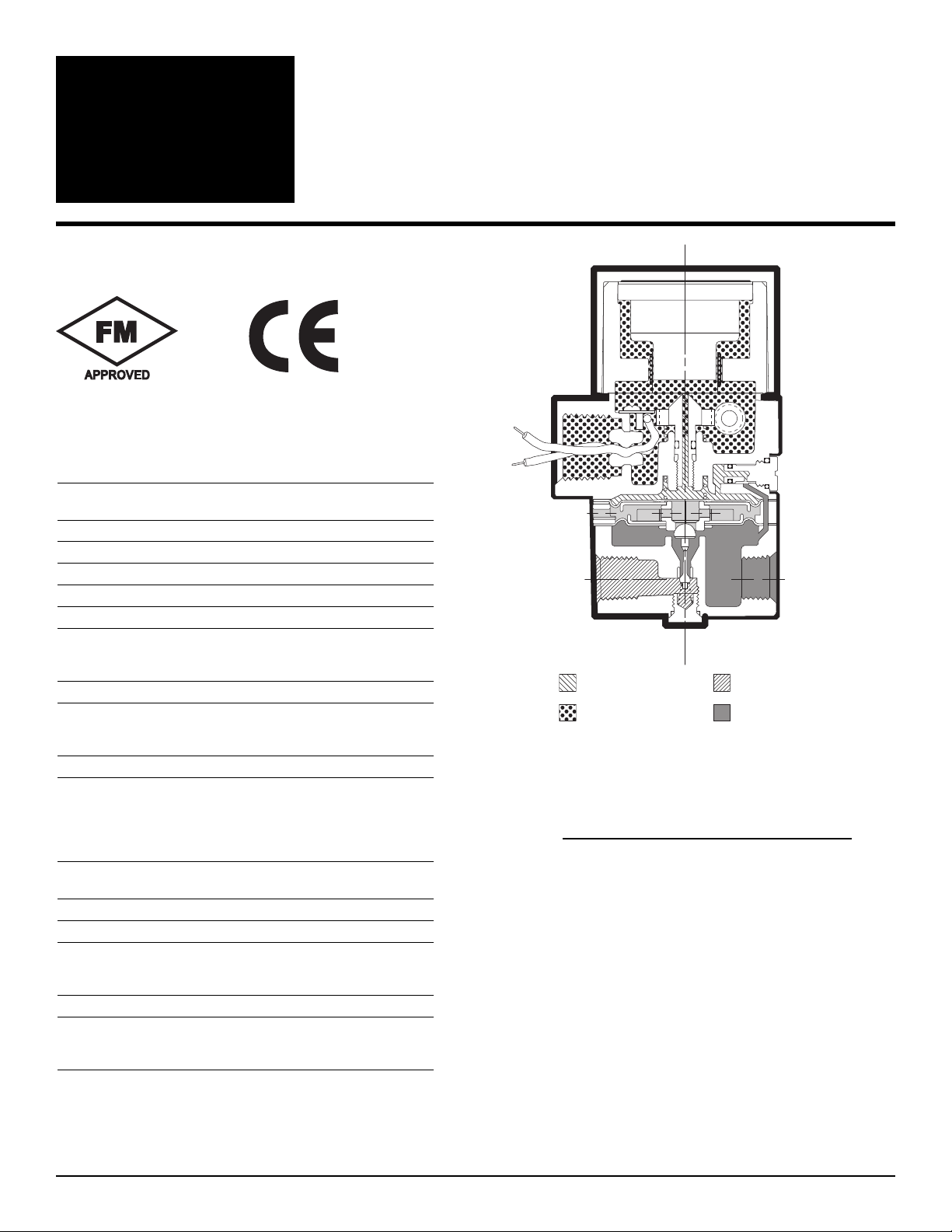
1.4.1 The 1/4 NPT supply and output ports are marked “IN” and “OUT” respectively on the base of the unit. Clean all
pipe lines to remove contamination before installation. Apply pipe compound to male threads of the air line only.
Avoid getting compound in the air lines.
Clean dry instrument quality air must be used. To insure optimum performance supply pressure should be
regulated. To provide stable inlet pressure and prevent contamination of the internal section of the transducer the
use of an Instrument Air Filter Regulator is recommended.
The two unmarked ports on the base of the unit are gage ports but may be used as alternative output ports. Any
unused ports must be plugged.
The I/P transducer enclosure contains aluminum and is considered to constitute a potential risk of
ignition b impact or friction and must be taken into account during installation.
1.5 Electrical Connections
1.5.1 Electrical connections are made to the black and white leads extending out from the 1/2 NPT conduit fitting.
When the positive side of the input signal is connected to the black lead, the output pressure will increase as the
input signal increases. For reverse acting mode (increasing input signal decreases output pressure), connect
positive side of the input signal to the white lead.
Fi ure 1 DIN 43650 Connector
2. OPERATION
2.1 Calibration
2.1.1 Zero and pan should always be checked after mounting. If unit is calibrated in a vertical position and then
mounted at an angle, readjustment of the zero is necessary. To calibrate use the following procedure:
1. Open protective covers to expose zero and span adjustment screws.
2. Connect the recommended air supply to the inlet of the transducer and an accurate pressure gage to the outlet.
3. Connect the electrical input and set the input signal to the minimum value of the range being used
(e.g. 4 mA for a 4-20 mA unit).
4. Observe the output pressure. If necessary adjust zero screw until reaching minimum output pressure setting.
Turn zero screw counter clockwise to increase pressure, clockwise to decrease pressure.
If unable to achieve output during calibration process, turn zero adjustment screw counter
clockwise for up to 30 revolutions, until output pressure rises.
5. Increase electrical input signal to its maximum value (e.g. 20 mA for a 4-20 mA unit).
6. Observe the output pressure. If necessary adjust the span screw until reaching maximum output pressure setting.
For I/P (current) input models turn span screw counter clockwise to increase pressure,
clockwise to decrease pressure. For E/P (voltage) input models turn span screw clockwise
to increase pressure, counter clockwise to decrease pressure.
7. The Zero and pan adjustments are interactive. After adjusting the span it will be necessary to recheck the zero.
Repeat steps 3-6 until both end points are at the required values.
8. For reverse acting performance interchange the black and white electrical signal leads and carry out the same
procedure as described above. Adjust the zero screw with minimum input (4mA) to get maximum output then
adjust span screw with maximum input (20mA) to get minimum output. Repeat as necessary.
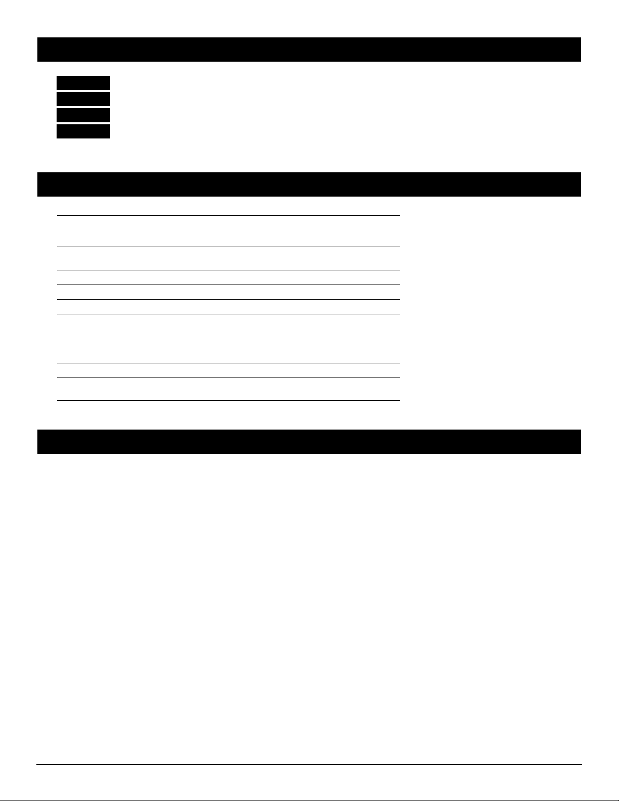
Fi ure 2 Electrical Schematic
WARNING
NOTE
NOTE
Notes:
1. For 4-20 mA and 10- mA use J1 as positive input.
2. For 10-50 mA change R4 to 100 Ohms.
3. For 1-9 VDC and 0-10 VDC remove R2, use J5 as
positive input.

2.2 Dimensional Drawin s (Dimensions are )
2.3 Intrinsically Safe Operation
2.3.1 ControlAir, Inc. offers Factory Mutual Intrinsically afe
approval as a standard feature on all units with a 4-20 mA input signal.
in.
mm
441-622-015 Type 500X Page 4
1.10
27.9
.55
14.0
(2) #18 GA. Wire Leads,
18" Long.
Black = Positive
White = Negative
(2) #10-32 UNF-2A x .38 DP.
Mounting Holes (Shown with
Bracket Screws Installed)
1.15
29.2
1.12
28.4
4.24
107.7
1.13
28.7
1.04
26.4
1.50
38.1
1.50
38.1
.55
14.0
1.13
28.7
Diameter
2.88
73.1
.21
.53
Diameter
MNTG.
Holes
1.250
31.7
2.18
55.4
1.44
36.6
SIGNAL
1/4
NPT
TYP.
Removable
Mounting
Bracket
1/2
NPT
IN OUT
Max (Square)
SPAN
ZERO
Alternate
Out/Gauge
Port
TYP. 180°Apart
Drawing No. 431-990-013
Models 728+, 787S+ and 4045, +24 to +26 VDC, Model 728-, -24 to -26 VDC,
available from MT Inc. 7541 Gary Road, Manassas, VA 221110, USA.

441-622-015 REV 05-23-11 Type 500X Page 5
3. MAINTENANCE
Under normal circumstances, no maintenance should be required. If clean dry air is not used the orifice can become blocked. To
clean, first turn off supply air, unscrew and remove orifice assembly (large silver screw head located above the out port). Then
unplug orifice by using a wire that has a smaller diameter than 0.015 in. (0.38 mm). Use compressed air to blow out any loose
particles inside the orifice assembly. crew orifice assembly back into unit.
4. TROUBLESHOOTING
PROBLEM CHECK
No output or low output Zero adjustment
upply pressure too low
Clogged orifice
Leakage Connections
Low or improper span Zero and pan adjustments
upply pressure too low
Output leakage
Erratic operation Electrical input signal
Loose wires or connections
Liquid in air supply
Lead Wire
Bonnet
O-Ring
O-Ring
Body Subassembly
Circuit
Board
Bottom Plug
Spacer
Pintle Spring
This manual suits for next models
20
Table of contents
Other controlair Transducer manuals
Popular Transducer manuals by other brands

S+S Regeltechnik
S+S Regeltechnik AERASGARD RCO2-W-A Operating Instructions, Mounting & Installation

Airmar
Airmar R299 Owner's guide and installation instructions

Lowrance
Lowrance StructureScan 3D installation manual

Garmin
Garmin GT15M-IH installation instructions

ADZ Nagano
ADZ Nagano ADZ-SML Ex Zone2/22 operating instructions

MKS
MKS 901P Short form manual