Converters.TV 718 User manual

Wireless Multi-Format input
Transmitter to HDMI
Receiver Box ID # 718
Operation Manual

Introduction
The wireless HDMI transmitter and receiver boxes use baseband
technology with Wireless High Definition Interface (WHDI) to deliver
uncompressed HD audio and video It can transmit within a distance of 20
meters while maintaining superb, wired equivalent quality and reliability
with little to no lag Both transmitter and receiver boxes come with built in
antennas, making them a sleek addition to your Home or Office These
units can also convert analog and digital signals to HDMI V1 2 in order to
be shown on displays
Applications
Multi format input to wireless HDMI output
Integrate your home entertainment system
Showroom Display
System
Requirements
Input source equipment(s) and output display device(s) with HDMI cables.
eatures
Uncompressed HD audio/video wireless transmission at wire-
equivalent quality
Supports most video resolutions including 80i/p, 576i/p, 720p, 1080i,
VGA@60/72Hz, SVGA@56/60/72Hz, XGA@60/70Hz and
1080p@2 /30fps
Supports analog/digital video/audio input and HDMI output to display
HDCP keysets allows each HDMI input to independently connect to
an HDMI display
Supports 3D comb filter and 3D noise reduction (DNR)
Supports 3D noise reduction (DNR)
Supports analog format conversion from 80i/576i to 80p/576p with a
hot key on the transmitters front panel and remote control
Operational within a distance of 20 meters, no direct line of sight
required.
Real time link, with a lag of less than 2 milliseconds.
Strong 256-bit AEC based encryption for security
Video Data Rates 1.5Gbps
5GHz licensed band, MIMO(Multiple Input Multiple Output) RF
Supports CEC bypass and input switch functionality
Fully HDCP Compliant
Operational in either Unicast or Broadcast mode
Auto shutdown when one of the devices is turned off
Instant signal transmission with a timing change of less than 10
seconds.
Control Channel allows two-way communications of 10Kbps
Audio support PCM (2CH), DTS (5.1CH) & AC3 (5.1CH)

Operating
Controls
Transmitter
ront Panel
The following sections describe the hardware components of the unit with
installation guide and setting methods
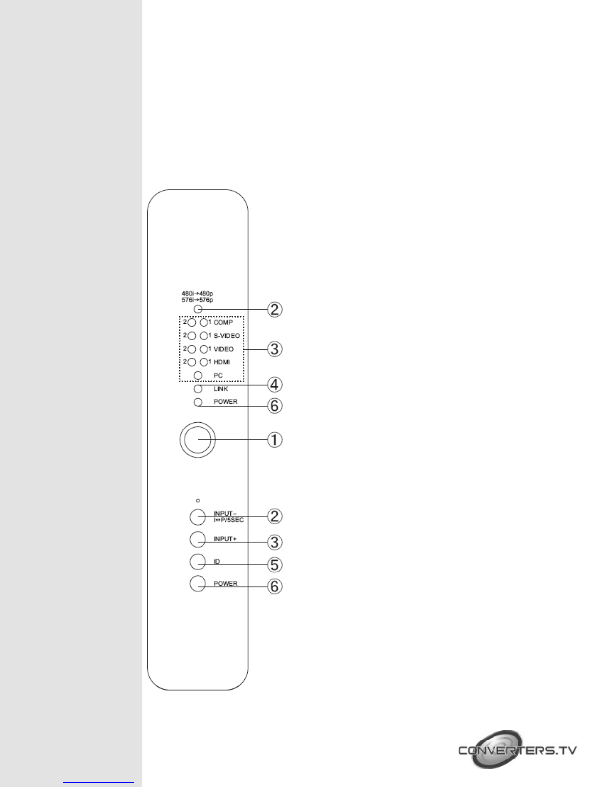
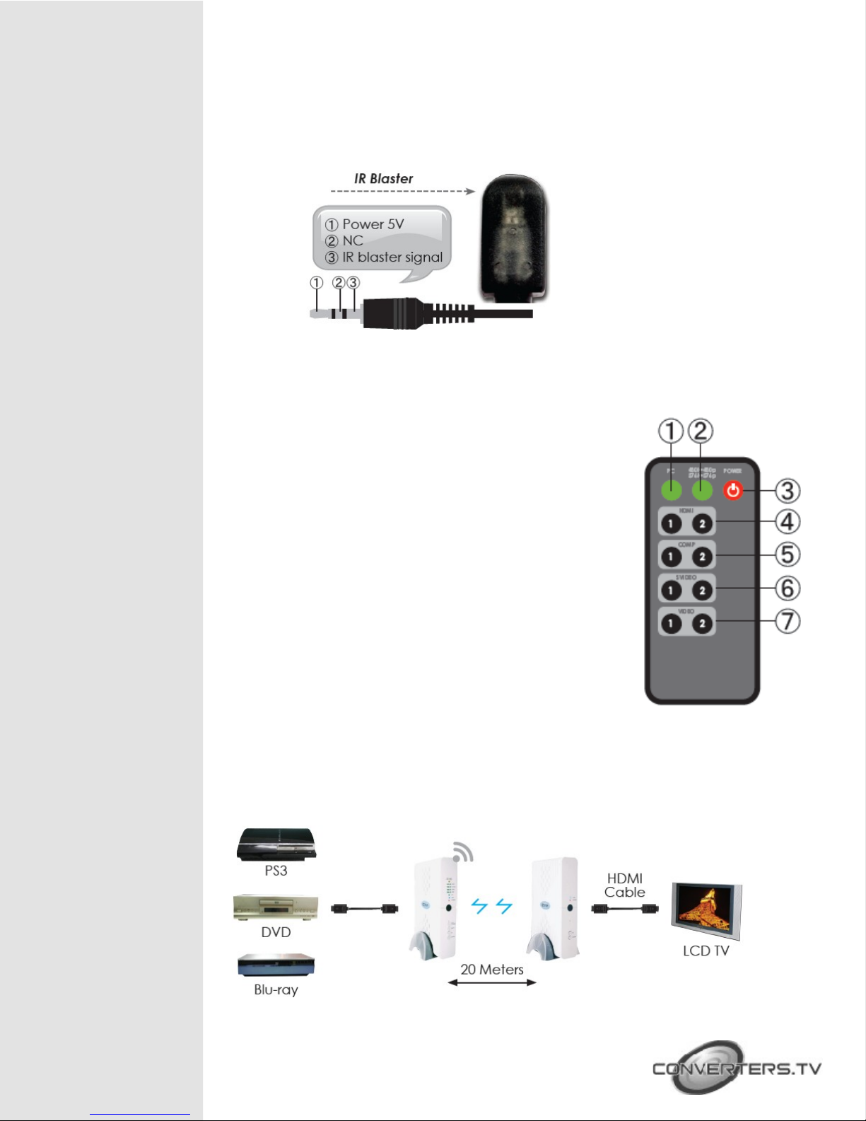
① IR sensor
②480i → 480p / 576i → 576p LED indicator and
INPUT -I P/5SE button: Press this button to
select the input source from COMP1 to PC or
press for 5 seconds to switch between interlace
and progressive format, yellow LED light will turn
on when switched from interlace to progressive
format, when switching from progressive to
interlace the light will not turn on
③Input source selection: Press the input button
to switch to your desired input sources from PC
to COMP1, green LED will illuminate according
to your selection
④ Link LED: When the system is in search mode
the blue LED will flash repeatedly, and when it is
in signal linking mode it will slowly flash When
the LED is on and there is no flashing it means
the system is ready and audio or video can be
sent
⑤ID: Press this button with the receivers “ID”
button for two seconds to connect the systems
Before they left the factory the systems were
already connected so there is no need for the
user to reset the connection unless the systems
cannot link up properly Press the ID button for
more than ten seconds to switch between
Broadcast and Unicast mode When the green
LED is on it means the system is in Unicast mode
and when the Red LED is lit the system is in
Broadcast mode The default mode for this
system is Unicast and it is recommended to use
this for home use It is not necessary to press
both the transmitter and receiver buttons at the
same time
Note: Due to the nature of Broadcast mode,
which has no uplink, there can be no
communication between Transmitter and
Receiver, the result is the following:
• HDCP protected content should not be
transmitted
• CEC and EDID repeater functions cannot be
supported

• Broadcast mode is not HDCP compliant
• Only supports single transmitter link with multiple
receivers
⑥Power: The LED will illuminate when power is on
Rear Panel
① omponent inputs: These slots are for
connecting the component and R/L output
ports of your source equipments such as DVD
player or set-top-box with component video and
R/L cables Y1, Pb/Cb1,Pr/Cr1, & Audio1 and Y2,
Pb/Cb2, Pr/Cr, & Audio2 are two individual loops
for source equipments
②Video/S-Video inputs: These slots are for
connecting the Video/S-Video and Audio (R/L)
output ports of your source equipments such as
DVD player or set-top- box with S-Video and
RCA cables The SVideo1, Video1, & Audio1 and
SVideo2, Video2, & Audio2 are two individual
loops for source equipments
③P - in-AUDIO: These slots are for connecting
the PC and or audio output port of your source
equipment such as Notebook or PC with D-
Sub15pin and R/L cables
④HDMI inputs 1/2: These slots are for connecting
the HDMI or DVI output ports of your source
equipments such as DVD player or set-top-box
with HDMI cables
⑤Power: Plug the 5V DC power supply included
in the package into this unit and connect the
adaptor to an AC wall outlet
⑥IR Blaster: Connect the IR blaster cable
included in the package and place it in front of
the source equipments The IR blaster will
transmit the infrared signal to the connected
source with the existing remote signal sent to this
device

Receiver
ront Panel
① Link LED: When the system is in search mode
the LED will flash repeatedly and when the system
is in signal linking mode it will slowly flash When
the LED is on and no longer flashing it means a
connection has been established and audio/
video can then be sent
②Power button: Press this button to power up the
system, when the LED is lit the system has been
turned on
③IR Sensor
④ID: Press this button along with Transmitters “ID”
button for two seconds to connect the systems
Before they left the factory the systems were
already set up so there is no need for the user to
reset the connection unless the systems cannot
link up properly Press the ID button for more than
ten seconds to switch between Broadcast and
Unicast mode When the green LED is on it means
the system is in Unicast mode and when the Red
LED is lit the system is in Broadcast mode The
default mode for this system is Unicast and it is
recommended to use this for home use It is not
necessary to press both the Transmitter and
Receiver buttons at the same time

Rear Panel
① HDMI output: This slot is to connect the HDMI
cable to the HDMI input of your display
②Power: Plug in the 5V DC power supply included
in the package and connect the adaptor to an AC
outlet

IR Cable Pin
Definitions
Note: The frequency on both IR Receiver & Blaster can support
36~387KHz with NEC code
Remote Control
① P : Press this button to select PC input
② Format selection: Press this button to switch between
Interlace and Progressive format
③ Power: Press this button to turn on/standby the unit
④ HDMI 1/2: Press no 1 or 2 buttons to select HDMI 1 or 2
inputs
⑤ omponent 1/2: Press no 1 or 2 buttons to select
Component 1 or 2 inputs
⑥ S-Video1/2: Press no 1 or 2 buttons to select S-Video 1 or
2 inputs
⑦ Video1/2: Press no 1 or 2 buttons to select Video 1 or 2
inputs
Connection and
Installation
Unicast Mode

Broadcast Mode
Remote Control distance

Input Signal
Specifications
P Resolution Vert Rate
VGA 640x480 60/72Hz
SVGA 800x600 56/60/72Hz
XGA 1024x768 60/70Hz
HDTV Resolutions Vert Rate
480p 720x480 60Hz
480i 720x480 60Hz
576p 720x576 50Hz
576i 720x576 50Hz
720p 1280x720 50, 60Hz
1080i 1920x1080 50, 60Hz
1080p 1920x1080 24, 30fps
Output Signal
Specifications
P Resolution Vert Rate
VGA 640x480 60/72Hz
SVGA 800x600 56/60/72Hz
XGA 1024x768 60/70Hz
HDTV Resolutions Vert Rate
480p 720x480 60Hz
480i 720x480 60Hz
576p 720x576 50Hz
576i 720x576 50Hz
720p 1280x720 50, 60Hz
1080i 1920x1080 50, 60Hz
1080p 1920x1080 24, 30fps

Specifications
Radio Power Transmit power is configurable up to
63mW (+18dBm)
Video Resolutions 480i/p, 576i/p, 720p, 1080i, VGA@60/72Hz,
SVGA@56/60/72Hz, XGA@60/70Hz and
1080p@24/30fps
Frequencies Supported 4 9 ~ 5 9GHz
Modulation MIMO OFDM with WHDI video-modem
technology
Bandwidth 18MHz
Wireless Range 20 meters open field
Antenna Transmitter: 4 transmit antennas and 2
receive antenna
Receiver: 5 receiver antenna and 1
transmit antenna
Digital Video Interface Up to 24 bit RGB or YCbCr (4:4:4)
System Latency Less than 1 millisecond delay between
video/ audio source and sink
Security Strong 256 bit AES-based encryption
Application Bandwidth Control Channel allows two-way
communications of 10Kbps
Input ports 2 x Components with R/L
2 x Video and 2 x S-Video with R/L
2 x HDMI
1 x PC with R/L
1 x IR Blaster
Output port 1 x HDMI
Power Supply Transmitter: 5V/6A DC (US/EU standards,
CE/FCC/UL certified)
Receiver: 5V/2 6A DC (US/EU standards,
CE/FCC/UL certified)
ESD Protection Human body model:
± 10kV (air-gap discharge)
± 6kV (contact discharge)
Dimensions (mm) Transmitter: 226(W) x 165(D) x 46(H)
Receiver: 226(W) x 165(D) x 46(H)
Weight(g) Transmitter:500
Receiver:440
hassis Material Plastic
Silkscreen olor White
Operating Temperature 0˚C ~ 40˚C / 32˚F ~ 104˚F
Storage Temperature -20˚C ~ 60˚C / -4˚F ~ 140˚F
Relative Humidity 20~90% RH (non-condensing)
Power onsumption Transmitter: 13 5W
Receiver: 7 6W
Table of contents
Other Converters.TV Receiver manuals

Converters.TV
Converters.TV 865 User manual

Converters.TV
Converters.TV Cat5 Cable - 50m User manual

Converters.TV
Converters.TV 888 User manual

Converters.TV
Converters.TV 15225 User manual

Converters.TV
Converters.TV 922 User manual

Converters.TV
Converters.TV 547 User manual

Converters.TV
Converters.TV 15493 User manual

Converters.TV
Converters.TV 789 User manual

Converters.TV
Converters.TV 995 User manual

Converters.TV
Converters.TV HDMI over CAT5e/6/7 Receiver User manual