EXT-0084-R00-12302020 (LTR) 1/13
O +1 604 273 2665
F +1 604 273 2660
T +1 844 455 4448
W cooledgelighting.com
Cooledge Lighting Inc.
110-13551 Commerce Parkway
Richmond, BC V6V 2L1 Canada
Cooledge Lighting reserves the right to change
materials or modify the design of its product
without notification as part of the company’s
continuing product improvement program.
5 Year Limited Warranty:
Parts and workmanship
E354088 E354088
E354088
E354088
58VDC
E354088
LISTED
Tc
5
5
Y
E
A
R
W
A
R
R
A
N
T
Y
5
Y
E
A
R
W
A
R
R
A
N
T
Y
For detailed instructions,
please refer to: EXT-0071
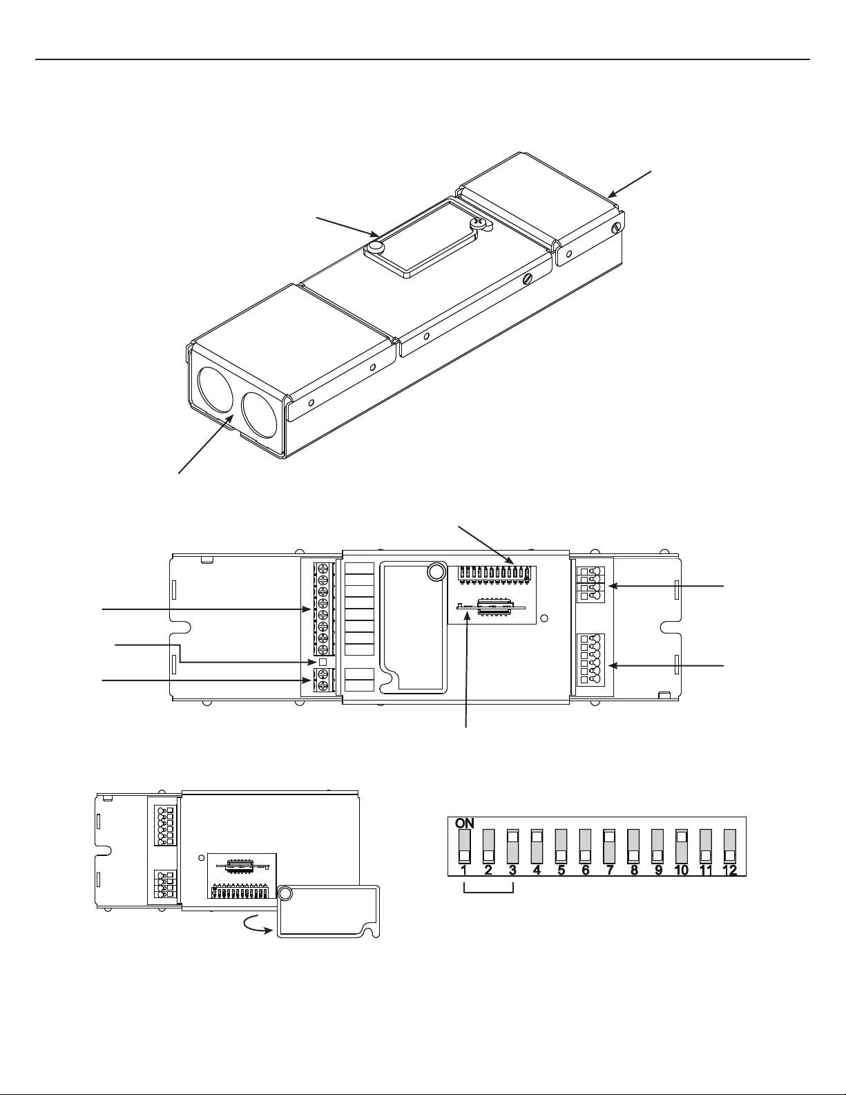
COOLEDGE CONTROL MODULE
USER GUIDE
Avaliable at
cooledgelighting.com
Control Module is suitable for use in dry locations only (IP20). Damage to CONTROL MODULE and/or light sheets may occur if wired incorrectly.
All devices should always be disconneced from mains power
supply and verify its absence prior to installation/maintenance.
FCC STATEMENT:
This device complies with part 15 of the FCC rules. Operation is subject to the
following two conditions:
(1) This device may not cause harmful interference.
(2) This device must accept any interference received, including interference that
may cause undesired operation.
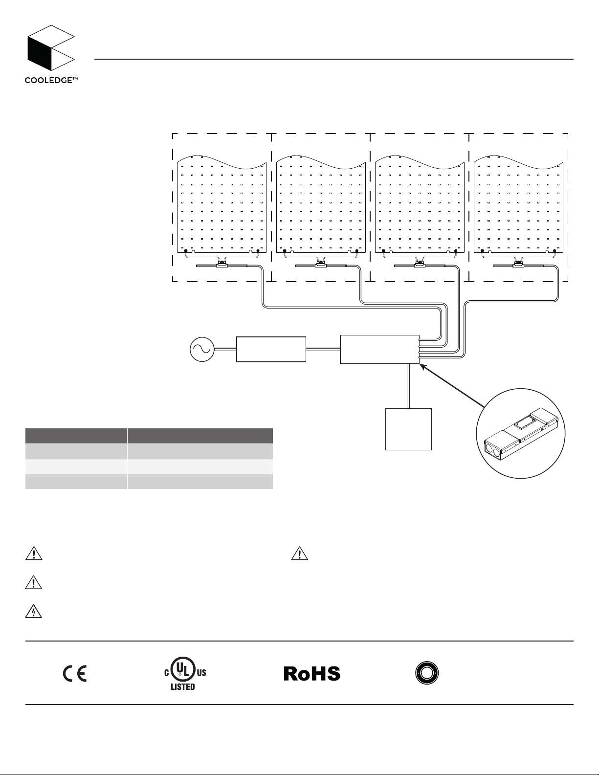
CONTROL MODULE must be installed by a qualified electrician.
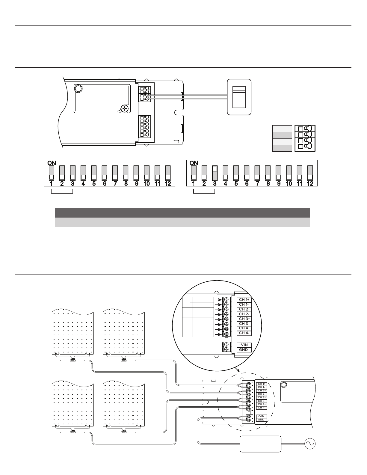
90W 90W 90W 90W
58V*
AC
POWER
SUPPLY (PSU)
CONTROL
MODULE
0/1 - 10V
* For use with 58VDC power supplies ONLY.
COOLEDGE POWER & CONTROL - USER GUIDE
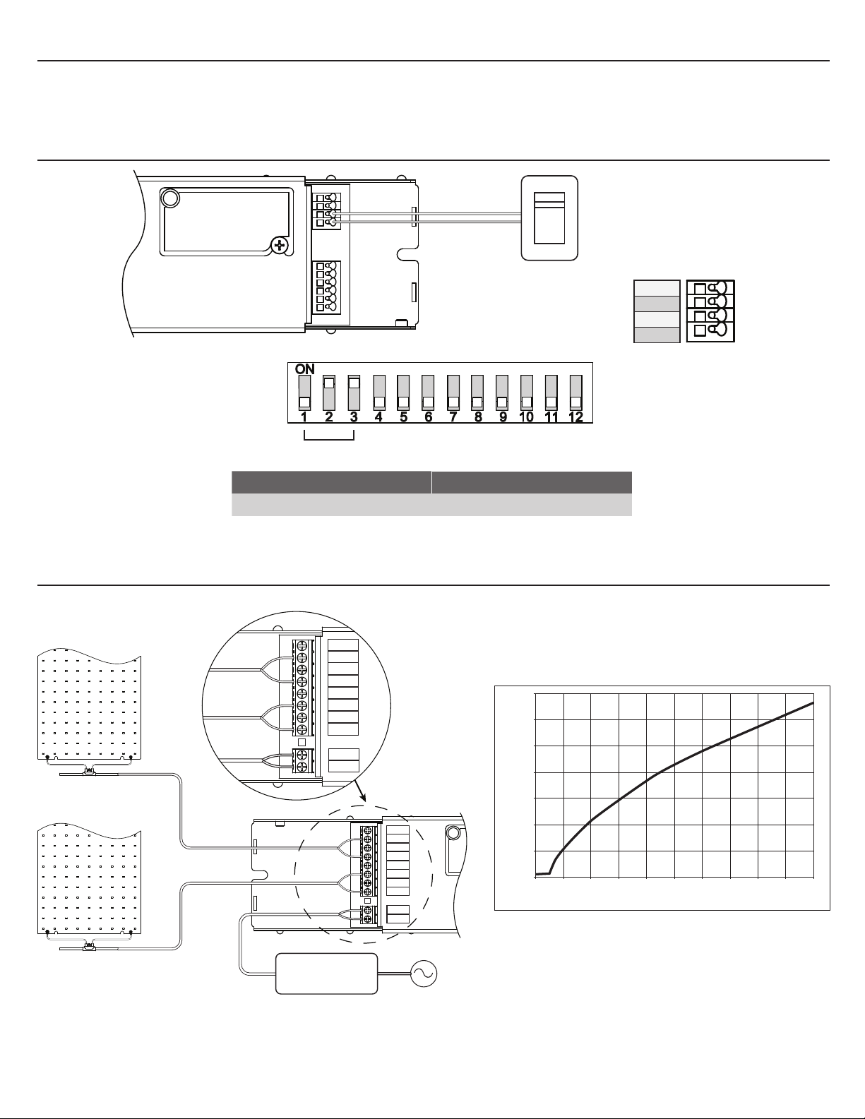
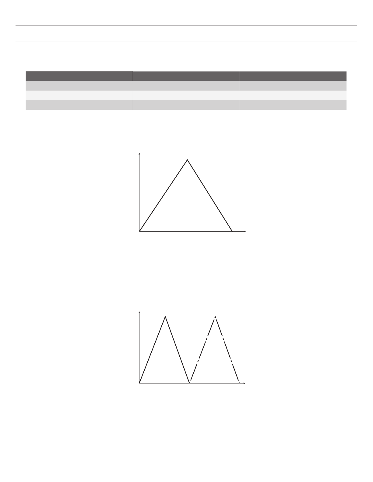
0-10V CONTROL
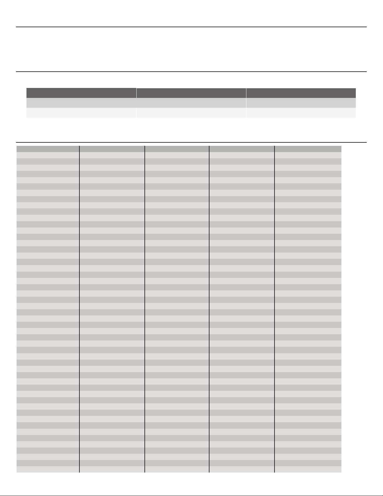
Compatible Part No’s Mode
CTR-SCT-DAL-58V Static Color Temperature SCT (Page 4)
CTR-TNW-DAL-58V Tunable White TNW (Page 5)
CTR-DTW-DAL-58V Dim-To-Warm DTW (Page 6)