manuals.online logo
Brands
  1. Home
  2. •
  3. Brands
  4. •
  5. Cooledge
  6. •
  7. Lighting Equipment
  8. •
  9. Cooledge FABRICOLOR User manual

Cooledge FABRICOLOR User manual

EXT-0091-R00-02262020 (LTR) 1/22
Cooledge FABRIColor is a simple, out-of-the-box
way to incorporate the unique look and feel of a
stretch fabric ceiling into your space. Create a canopy
of light in T-bar grid ceilings by adding skylights to
provide immersive illumination that delivers the
visual, biological, and emotional benefits of large
luminous surfaces.
Grid (T-Bar) luminaires deliver immersive illumination for:
• Oces
• Healthcare facilities
• Meeting rooms
• Educational buildings
Features Cooledge’s unique “Infinity Edge” design
for uniform illumination from edge to edge.
1. COMPONENTS
Suspension Cable
Cable Gripper
Hanger Bracket
Control Module
Power and Control Tray
Power Supply
Trim Clip
Trim
Corner
Trim
O +1 604 273 2665
F +1 604 273 2660
T +1 844 455 4448
W cooledgelighting.com
Cooledge Lighting Inc.
110-13551 Commerce Parkway
Richmond, BC V6V 2L1 Canada
Cooledge Lighting reserves the right to change
materials or modify the design of its product
without notification as part of the company’s
continuing product improvement program.
COOLEDGE LUMINOUS CEILINGS
FABRICOLOR - GRID (T-BAR)
INSTALLATION GUIDE
5 Year Limited Warranty:
Parts and workmanship
5
5
Y
E
A
R
S
Y
S
T
E
M
W
A
R
R
A
N
T
Y
5
Y
E
A
R
S
Y
S
T
E
M
W
A
R
R
A
N
T
Y
EXT-0091-R00-02262020 (LTR) 2/22
2. TOOLS
CAUTION: Observe precautions for handling electrostatic sensitive devices.
WARNING: Wear clean cotton or latex gloves when handling Cooledge FABRIColor.
Do not remove the plastic protective film until the point noted in this install guide.
!
CAUTION: Use appropriate Personal Protective Equipment (PPE) to ensure safety at work.
!
Measuring Tape
Level
#2 Phillips Screwdriver 3mm Flat Head Screwdriver 2x wrenches (only required
for threaded rod mounting)
Saw Horses
4mm and 5mm Hex Key
Gloves
Cable Cutters
EXT-0091-R00-02262020 (LTR) 3/22
NOTE: Leave protective
plastic film attached
3.1. REMOVE THE CEILING TILES AND ANY CROSS TEES TO GIVE CORRECT CEILING OPENING
3.2. UNPACK LUMINAIRE AND PLACE FACE DOWN ON SAW HORSES AT CORNERS
3.3. ATTACH POWER AND CONTROL TRAY(S) TO STIFFENERS
WARNING: Do not cut or remove any main beam tees. If this is required to make the correct opening size for the luminaire,
consult a ceiling contractor.
3. INSTALLATION PROCEDURE
NOTE: Lift luminaire
using handles provided
NOTE: Power Supply and
Control Module may vary
NOTE: Trays may be mounted remotely. In this case, the DC power connections should be made to the Luminaire (section 3.4) with
a suitable length of cable.
Refer to Section 8. APPENDIX – DMX CONTROL for setting up the control module.
NOTE: Ensure T-nuts rotate fully
inside channel to tighten correctly
EXT-0091-R00-02262020 (LTR) 4/22
8.7”
2.6”
1.4”
Black +
Red -
N/C
Green -
N/C
Blue -
N/C
White -
PSU
24V: 100/200/400
Control Module
5-conductor cable
to luminaire
Red
Green
Blue
White
Black
VIN
58V
DIM (-)
DIM (+)
VIN
0V
RED (+)
58V
BLACK (-)
To power
supply
To Controls
{Starter Cable
Do Not
Connect
Do Not
Connect
DO NOT
CONNECT
DO NOT
CONNECT
DO NOT
CONNECT
DO NOT
CONNECT
NOTE: The power and control tray type will vary depending on region and luminaire size.
3.4. CONNECT POWER AND CONTROL TRAY TO LUMINAIRE
NOTE: Lift luminaire
using handles provided
3.5. ESTABLISH THE REQUIRED POSITIONS FOR SUSPENSION CABLES
Either measure between the suspension points or refer to TABLE 1, PAGE 10.
EXT-0091-R00-02262020 (LTR) 5/22
3.6. ATTACH CABLES TO CEILING ANCHOR POINTS AT REQUIRED POSITIONS
3.7. ATTACH CABLES TO HANGER BRACKETS WITH GRIPPERS
EXT-0091-R00-02262020 (LTR) 6/22
3.8. RAISE LUMINAIRE TO JUST BELOW CEILING LEVEL
3.9. CONNECT THE ELECTRICAL POWER
The electrical power connections should be made by a qualified electrician in accordance with all national and local electrical and
construction codes.
Refer to Section 8. APPENDIX – DMX CONTROL for setting up the control module.
Leave space for electrician to make connection to power supply.
Connect AC to Power Supply
NOTE: Power Supply and
Control Module may vary
EXT-0091-R00-02262020 (LTR) 7/22
3.11. ATTACH TRIM WITH PROVIDED CLIPS
3.10. REMOVE THE PROTECTIVE PLASTIC WRAPPING AND LIFTING HANDLES
Remove the lifting handles using a 4mm Hex Key.
Ensure you wear gloves from this point forward to prevent marks on the fabric.
3.12. ATTACH CORNER COVER TO TRIM
EXT-0091-R00-02262020 (LTR) 8/22
3.13. LIFT LUMINAIRE INTO FINAL POSITION
Access the cable grippers through adjacent ceiling grid opening and lift the luminaire until the trim is flush with the underside of the
ceiling grid.
WARNING: Overtightening the cables may lift the ceiling grid and cause damage to the luminaire.
CEILING TILE
CEILING GRID
TRIM PIECE FLUSH WITH
UNDERSIDE OF GRID
EXT-0091-R00-02262020 (LTR) 9/22
In general, Cooledge FABRIColor require little or no maintenance; however, if there is a need to handle or clean the luminaires,
Cooledge recommends the following procedures.
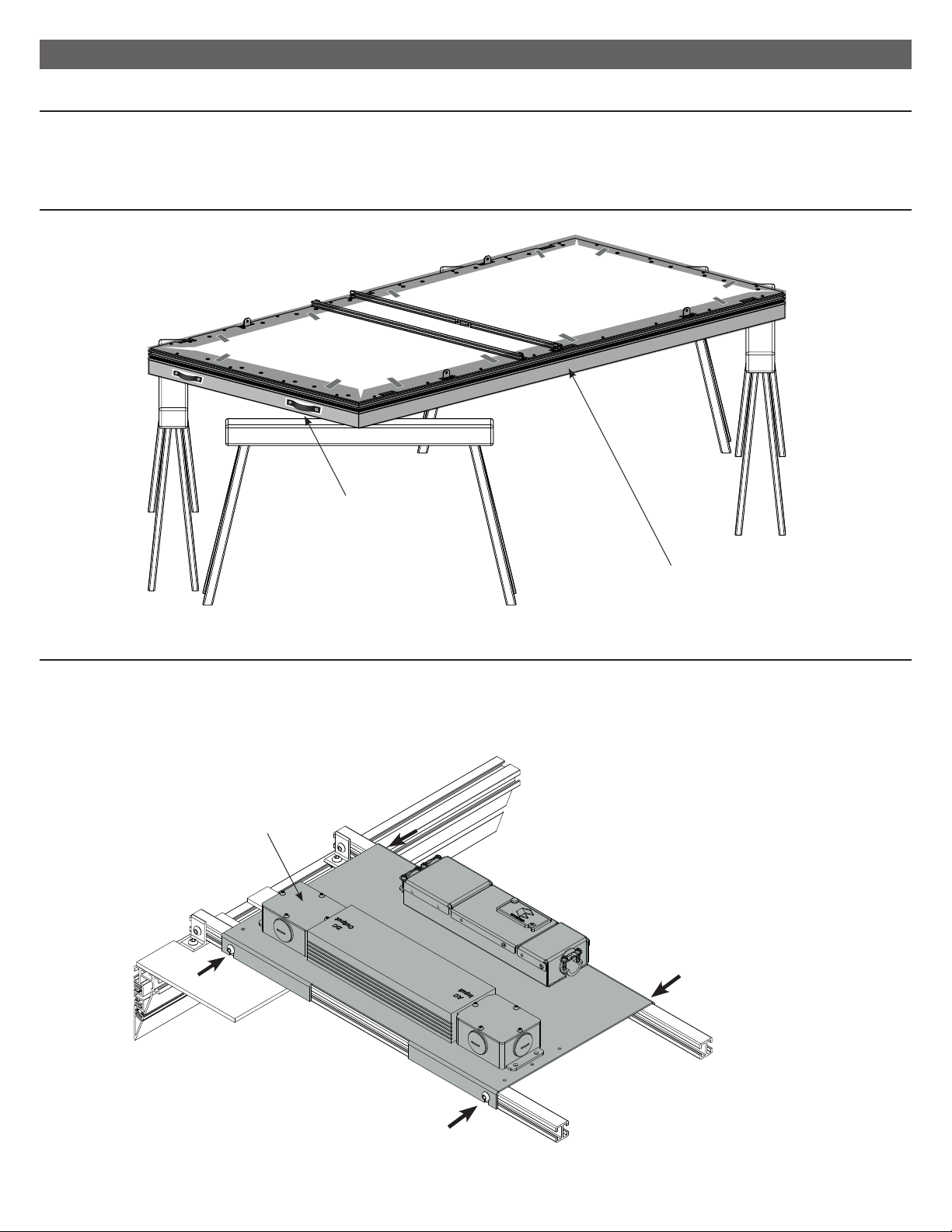
Handling:
• Always handle the luminaire from the sides and avoid touching the diuser to prevent fingerprints, oil, or dirt from marking the fabric.
• Always use cloth gloves if handling the fabric diuser.
Cleaning:
Fabric Diuser
Over time there may be some accumulation of dust from the environment. To remove dust there are several methods available including:
• Brush gently with a clean, micro fiber cloth or “magic eraser” (if available in your region)
• Vacuum with a clean brush-tip vacuum nozzle
• Blow with compressed air (ensure there is no oil or grease)
• Use an adhesive lint-roller (recommended to test a small area in case the specific type of roller leaves a residue)
For minor stains, spots or streaks, Cooledge recommends gently wiping the fabric with isopropyl alcohol, “IPA”, (99% or higher) applied
to a clean, soft cloth and allow to dry.
Note: use of liquids other than IPA to clean the fabric diuser may result in permanent stains. FABRICated Luminaires are rated for
dry locations only and should not be exposed to moisture or direct contact with water.
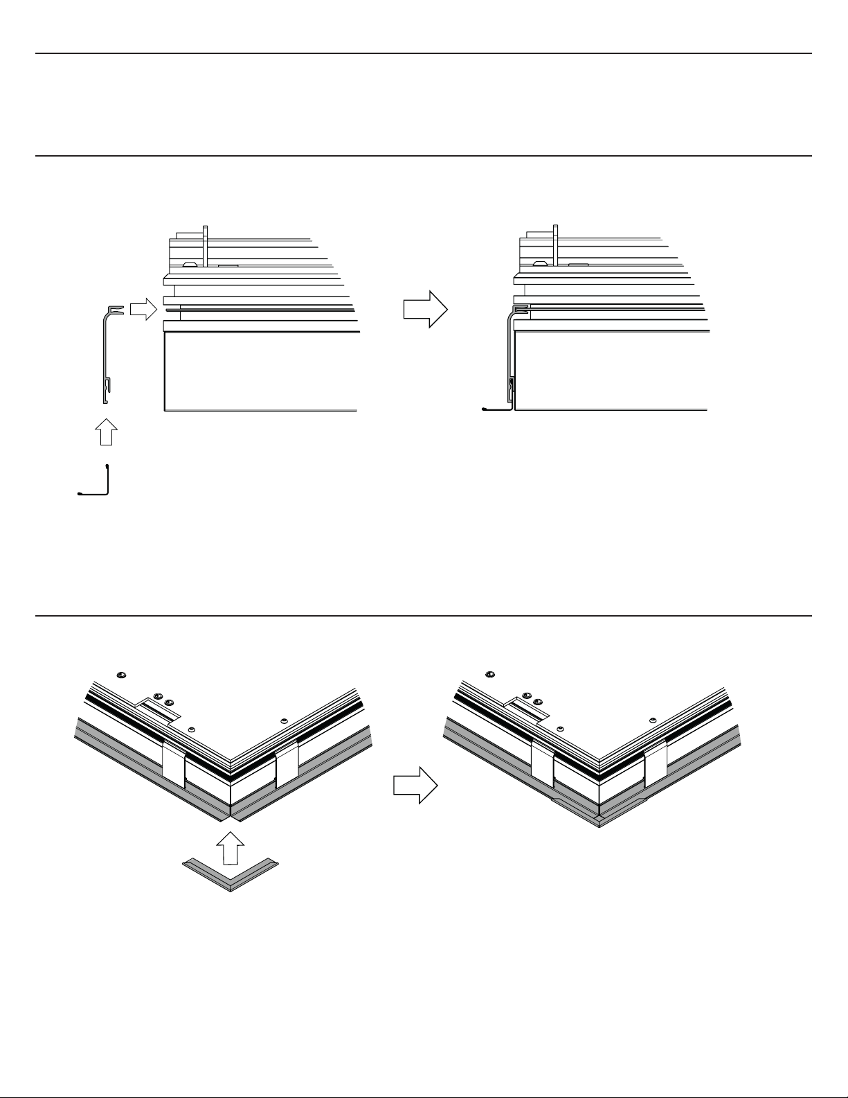
Trim/Fascia
• Wipe trim with a clean, soft cloth
4. HANDLING & MAINTENANCE
EXT-0091-R00-02262020 (LTR) 10/22
5.1. CABLE ATTACHMENT POINTS
5. APPENDIX – POSITIONS OF SUSPENSION POINTS
y
y
xx
C
L
C
L
C
L
C
L
TABLE 1
NOMINAL SIZE # SUSPENSION POINTS DIM “X” DIM “Y”
4’ X 4’ 420 ⁄” 22 ⁄”
4’ X 6’ 4 21 ⁄” 22 ⁄”
4’ X 8’ 4 26 ⁄” 22 ⁄”
1200mm X 1200mm 4 525mm 550mm
1200mm X 1800mm 4550mm 550mm
1200mm X 2400mm 4655mm 550mm
EXT-0091-R00-02262020 (LTR) 11/22
Control Module overview
CH 1+
CH 1-
CH 2+
CH 2-
CH 3+
CH 4+
CH 3-
CH 4-
+VIN
GND
Output Channel
and Power Input Cover
DIP Switch
Cover
Controls Input
Cover
Output
Channels
Status LED
Power
Input
Mode and Addressing DIP Switch
DMX
Inputs
DMX
To access the DIP switches for selecting the operational mode, unfasten the cover screw and rotate cover out of the way.
Positions 1-3 are used to identify the controller mode. Settings for each mode are explained in each section.
- Switches 1 - 3: Control Module MODE
Black +
Red -
N/C
Green -
N/C
Blue -
N/C
White -
8. APPENDIX – DMX CONTROL
EXT-0091-R00-02262020 (LTR) 12/22
- To access the dip switch for selecting addresses for DMX controls, unfasten the cover screw and rotate cover out of the way.
DMX Controllers are factory set to address 1
- Each of the 9 switches (4-12) represents a bit in binary representation for the address. For example, when switch 12 is ‘ON’ only
address 1 is selected, if switch 12 & 11 are ‘ON’ then address 3 is selected. The address is selected by the sum of the values of
each ‘ON’ switch. Addresses 1 through 511 are possible
In standard mode there are Red, Green, Blue, and White channels. Each can handle up to a 90W load.
Switch: 4 5 6 7 8 9 10 11 12
Address: 256 128 64 32 16 8 4 2 1
SELECTING DMX ADDRESSES
- Switches 1 - 3: Factory set, refer to modes below for details.
- Switches 4 - 12: Addressing switches.
1 = On , 0 = O
DMX
DMX OUTPUT
GND
D-
D+
DMX INPUT
GND
D-
D+
When installing the final controller (termination
point) in a DMX network use the provided jumper
on the indicated header.
DMX
STANDARD MODE
EXT-0091-R00-02262020 (LTR) 13/22
Table 1:
STANDARD MODES 8bits/16bits MODE (Pos 1-3) Switches 4-12 DESCRIPTION
DMX Standard LOG 16 bits 0-0-0 Addressing Standard LOG 16 bits
DMX Standard LIN 16 bits 0-0-1 Addressing Standard LIN 16 bits
DMX Standard LOG 8 bits 0-1-0 Addressing Standard LOG 8 bits
DMX Standard LIN 8 bits 0-1-1 Addressing Standard LIN 8 bits
- Switches 1 - 3: Control Module MODE
DMX OUTPUT
GND
D-
D+
DMX INPUT
GND
D-
D+
DMX
LOG MODE LIN MODE
Warning! Unit must be powered o when changing DIP switch settings
For STANDARD -16bit Modes- LOG or LIN- each Output Channel uses 2 x DMX Channels:
1 for DIM Coarse
1 for DIM Fine
In total, each controller occupies 8 x DMX channels, assigned as below:
DMX CH1 – DIM Coarse RED Channel
DMX CH2 – DIM Fine RED Channel
DMX CH3 – DIM Coarse GREEN Channel
DMX CH4 – DIM Fine GREEN Channel
DMX CH5 – DIM Coarse BLUE Channel
DMX CH6 – DIM Fine BLUE Channel
DMX CH7 – DIM Coarse WHITE Channel
DMX CH8 – DIM Fine WHITE Channel
Example of addressing units for 16-bit LIN/LOG Modes on DMX bus:
1. Unit 1 takes DMX Address = 1, and unit occupies DMX Channels # 1-8
2. Unit 2 takes DMX Address = 9, and unit occupies DMX Channels # 9-16
3. Unit 3 takes DMX Address = 17, and unit occupies DMX Channels # 17-24
For the above the DIP SETTINGS are:
1. 000 000000001 Controller set for 16-bit LIN/LOG Mode, unit occupies DMX Channels 1-8
2. 000 000001001 Controller set for 16-bit LIN/LOG Mode, unit occupies DMX Channels 9-16
3. 000 000010001 Controller set for 16-bit LIN/LOG Mode, unit occupies DMX Channels 17-24
EXT-0091-R00-02262020 (LTR) 14/22
For STANDARD -8bit LIN/LOG Modes - each Output Channel uses 1x DMX Channel:
In total, each controller occupies 4 x DMX channels, assigned as below:
DMX CH1 – DIM RED Channel
DMX CH2 – DIM GREEN Channel
DMX CH3 – DIM BLUE Channel
DMX CH4 – DIM WHITE Channel
Example of addressing units for 8-bit LIN/LOG Modes on DMX bus:
1. Unit 1 takes DMX Address = 1 and unit occupies DMX Channels # 1-4
2. Unit 2 takes DMX Address = 5 and unit occupies DMX Channels # 5-8
3. Unit 3 takes DMX Address = 9 and unit occupies DMX Channels # 9-12
For the above the DIP SETTINGS are:
1. 000 000000001 Controller set for 8-bit LIN/LOG Mode, unit occupies DMX Channels 1-4
2. 000 000000101 Controller set for 8-bit LIN/LOG Mode, unit occupies DMX Channels 5-8
3. 000 000001001 Controller set for 8-bit LIN/LOG Mode, unit occupies DMX Channels 9-12
For 16-bit Standard Modes the dimming curves are shown below:
16-bit LINEAR DIMMING CURVE
DMX INPUT
%
DUTY CYCLE (%)
0 50 100 150 200 250
100
80
60
40
20
0
16-bit LOG DIMMING CURVE
DMX INPUT
%
DUTY CYCLE (%)
0 50 100 150 200 250 300
100
80
60
40
20
0
EXT-0091-R00-02262020 (LTR) 15/22
For 8-bit Standard Modes the dimming curves are shown below:
8-bit LOG DIMMING CURVE
DMX INPUT
%
DUTY CYCLE OUTPUT (%)
0 20 40 60 80 100 120 140
100
80
60
40
20
0
8-bit LIN DIMMING CURVE
%
DMX INPUT
DUTY CYCLE OUTPUT (%)
0 20 40 60 80 100 120 140
100
80
60
40
20
0
EXT-0091-R00-02262020 (LTR) 16/22
Standalone mode gives a pre-defined user-selectable fixed color output. No external control input is required.
When one of the operational modes (Standalone Fixed or Standalone Dynamic ) is selected through the DIP Switch setting, the
module will ignore DMX commands and operate according to the settings, as per table below.
Standalone Fixed Modes selection include:
- 8 x Fixed R, G, B, W colors
- 26 predefined mixed colors
- 6 x CCT white combinations
***DIP switch positions 4-7 are used to select 16 intensities for each of 32 fixed colors as shown in Table below:
STANDALONE MODE
Standalone Fixed Modes
STANDALONE FIXED
RGBW 8bits/16bits MODE (Pos 1-3) Switches 4-12 DESCRIPTION
FIXED RED LOG 1-0-0 X-X-X-X-X-X-X-0-0 RED channel fixed LOG for 16bit/8bit
FIXED RED LIN 1-0-0 X-X-X-X-X-X-X-0-1 RED channel fixed LIN for 16bit/8bit
FIXED GREEN LOG 1-0-0 X-X-X-X-X-X-X-1-0 GREEN channel fixed LOG for 16bit/8bit
FIXED GREEN LIN 1-0-0 X-X-X-X-X-X-X-1-1 GREEN channel fixed LIN for 16bit/8bit
FIXED BLUE LOG 1-0-1 X-X-X-X-X-X-X-0-0 BLUE channel fixed LOG for 16bit/8bit
FIXED BLUE LIN 1-0-1 X-X-X-X-X-X-X-0-1 BLUE channel fixed LIN for 16bit/8bit
FIXED WHITE LOG 1-0-1 X-X-X-X-X-X-X-1-0 WHITE channel fixed LOG for 16bit/8bit
FIXED WHITE LIN 1-0-1 X-X-X-X-X-X-X-1-1 WHITE channel fixed LIN for 16bit/8bit
FIXED 32 Colors with
16 intensities 110 X-X-X-X-X-X-X-X-X 32 Colors*** = X-X-X-X-X and 16 intensities = X-X-X-X
INTENSITY LEVEL DIP SETTING POS 4-7 OUTPUT %
1 0-0-0-0 1
2 0-0-0-1 5
3 0-0-1-0 10
4 0-0-1-1 15
5 0-1-0-0 20
6 0-1-0-1 25
7 0-1-1-0 30
8 0-1-1-1 35
9 1-0-0-0 40
10 1-0-0-1 45
11 1-0-1-0 50
12 1-0-1-1 60
13 1-1-0-0 70
14 1-1-0-1 80
15 1-1-1-0 90
16 1-1-1-1 100
EXT-0091-R00-02262020 (LTR) 17/22
DIP switch positions 8-12 are used to select 32 colors as shown in Table below:
COLOR NUMBER COLOR DIP SETTING POS 8-12
1 PINK 0-0-0-0-0
2 LIGHT PINK 0-0-0-0-1
3 VIOLET 0-0-0-1-0
4 FUCSHIA (MAGENTA) 0-0-0-1-1
5 PLUM 0-0-1-0-0
6 ORCHID 0-0-1-0-1
7 ORANGE 0-0-1-1-0
8 SALMON 0-0-1-1-1
9 CORAL 0-1-0-0-0
10 LIGHT CORAL 0-1-0-0-1
11 YELLOW 0-1-0-1-0
12 LIGHT VIOLET 0-1-0-1-1
13 OLIVE 0-1-1-0-0
14 AQUAMARINE 0-1-1-0-1
15 SPRING GREEN 0-1-1-1-0
16 LIGHT SEA GREEN 0-1-1-1-1
17 LIME GREEN 1-0-0-0-0
18 PALE GREEN 1-0-0-0-1
19 TURQUOISE 1-0-0-1-0
20 ROYAL BLUE 1-0-0-1-1
21 SKY BLUE 1-0-1-0-0
22 CYAN 1-0-1-0-1
23 POWDER BLUE 1-0-1-1-0
24 SLATE BLUE 1-0-1-1-1
25 LAVENDER 1-1-0-0-0
26 AZURE 1-1-0-0-1
27 2700K 1-1-0-1-0
28 3000K 1-1-0-1-1
29 3500K 1-1-1-0-0
30 4000K 1-1-1-0-1
31 5000K 1-1-1-1-0
32 5700K 1-1-1-1-1
EXT-0091-R00-02262020 (LTR) 18/22
For Standalone RED, GREEN, BLUE or WHITE Fixed Modes the dimming curves are shown below:
STANDALONE FIXED RGBW LIN DIM CURVE
OUTPUT (%)
DMX INPUT
%
0 20 40 60 80 100 120 140
100
80
60
40
20
0
STANDALONE FIXED RGBW LOG DIM CURVE
OUTPUT (%)
DMX INPUT
%
0 20 40 60 80 100 120 140
100
80
60
40
20
0
EXT-0091-R00-02262020 (LTR) 19/22
LOG DIP SETTINGS/DIMMING LEVELS FOR FIXED RGBW
1 0000000 0.05
2 0000001 0.21
3 0000010 0.24
4 0000011 0.24
5 0000100 0.27
6 0000101 0.27
7 0000110 0.29
8 0000111 0.32
9 0001000 0.32
10 0001001 0.35
11 0001010 0.37
12 0001011 0.4
13 0001100 0.4
14 0001101 0.43
15 0001110 0.46
16 0001111 0.49
17 0010000 0.51
18 0010001 0.54
19 0010010 0.57
20 0010011 0.58
21 0010100 0.59
22 0010101 0.62
23 0010110 0.64
24 0010111 0.67
25 0011000 0.69
26 0011001 0.72
27 0011010 0.73
28 0011011 0.76
29 0011100 0.78
30 0011101 0.81
31 0011110 0.84
32 0011111 0.87
33 0100000 0.92
34 0100001 0.94
35 0100010 0.98
36 0100011 1.02
37 0100100 1.06
38 0100101 1.1
39 0100110 1.15
40 0100111 1.2
41 0101000 1.23
42 0101001 1.3
43 0101010 1.34
44 0101011 1.4
45 0101100 1.45
46 0101101 1.51
47 0101110 1.59
48 0101111 1.66
49 0110000 1.74
50 0110001 1.8
51 0110010 1.89
52 0110011 1.98
53 0110100 2.07
54 0110101 2.17
55 0110110 2.25
56 0110111 2.37
57 0111000 2.47
58 0111001 2.61
59 0111010 2.73
60 0111011 2.87
61 0111100 3.01
62 0111101 3.16
63 0111110 3.32
64 0111111 3.48
65 1000000 3.67
66 1000001 3.85
67 1000010 4.04
68 1000011 4.24
69 1000100 4.47
70 1000101 4.71
71 1000110 4.95
72 1000111 5.2
73 1001000 5.47
74 1001001 5.76
75 1001010 6.07
76 1001011 6.39
77 1001100 6.73
78 1001101 7.1
79 1001110 7.47
80 1001111 7.87
81 1010000 8.3
82 1010001 8.75
83 1010010 9.21
84 1010011 9.71
85 1010100 10.24
86 1010101 10.8
87 1010110 11.36
88 1010111 12
89 1011000 12.65
90 1011001 13.35
91 1011010 14.07
92 1011011 14.85
93 1011100 15.65
94 1011101 16.52
95 1011110 17.43
96 1011111 18.4
97 1100000 19.4
98 1100001 20.46
99 1100010 21.6
100 1100011 22.8
101 1100100 24.06
102 1100101 25.38
103 1100110 26.8
104 1100111 28.3
105 1101000 29.85
106 1101001 31.51
107 1101010 33.25
108 1101011 35.11
109 1101100 37
110 1101101 39.13
111 1101110 41.3
112 1101111 43.6
113 1110000 46
114 1110001 48.6
115 1110010 51.3
116 1110011 54.18
117 1110100 57.2
118 1110101 60.4
119 1110110 63.8
120 1110111 67.35
121 1111000 71.1
122 1111001 75.1
123 1111010 79.28
124 1111011 83.71
125 1111100 88.4
126 1111101 93.35
127 1111110 98.58
128 1111111 100
LEVEL DIPSW
SETTING OUTPUT (%) LEVEL DIPSW
SETTING OUTPUT (%)
EXT-0091-R00-02262020 (LTR) 20/22
LIN DIP SETTINGS/DIMMING LEVELS FOR FIXED RGBW
1 0000000 0.05
2 0000001 1.15
3 0000010 1.95
4 0000011 2.73
5 0000100 3.51
6 0000101 4.31
7 0000110 5.1
8 0000111 5.87
9 0001000 6.67
10 0001001 7.46
11 0001010 8.24
12 0001011 9.03
13 0001100 9.82
14 0001101 10.6
15 0001110 11.4
16 0001111 12.18
17 0010000 12.98
18 0010001 13.75
19 0010010 14.55
20 0010011 15.33
21 0010100 16.12
22 0010101 16.91
23 0010110 17.7
24 0010111 18.48
25 0011000 19.28
26 0011001 20.05
27 0011010 20.85
28 0011011 21.64
29 0011100 22.42
30 0011101 23.2
31 0011110 24
32 0011111 24.78
33 0100000 25.58
34 0100001 26.35
35 0100010 27.15
36 0100011 27.92
37 0100100 28.72
38 0100101 29.51
39 0100110 30.3
40 0100111 31.08
41 0101000 31.88
42 0101001 32.65
43 0101010 33.45
44 0101011 34.22
45 0101100 35.01
46 0101101 35.81
47 0101110 36.6
48 0101111 37.37
49 0110000 38.17
50 0110001 38.95
51 0110010 39.75
52 0110011 40.53
53 0110100 41.32
54 0110101 42.1
55 0110110 42.9
56 0110111 43.68
57 0111000 44.47
58 0111001 45.25
59 0111010 46.05
60 0111011 46.83
61 0111100 47.63
62 0111101 48.4
63 0111110 49.19
64 0111111 49.97
65 1000000 50.77
66 1000001 51.55
67 1000010 52.34
68 1000011 53.12
69 1000100 53.92
70 1000101 54.7
71 1000110 55.49
72 1000111 56.27
73 1001000 57.07
74 1001001 57.85
75 1001010 58.65
76 1001011 59.42
77 1001100 60.21
78 1001101 61
79 1001110 61.8
80 1001111 62.58
81 1010000 63.38
82 1010001 64.15
83 1010010 64.95
84 1010011 65.73
85 1010100 66.51
86 1010101 67.3
87 1010110 68.08
88 1010111 68.88
89 1011000 69.67
90 1011001 70.45
91 1011010 71.24
92 1011011 72.02
93 1011100 72.82
94 1011101 73.6
95 1011110 74.4
96 1011111 75.18
97 1100000 75.98
98 1100001 76.75
99 1100010 77.54
100 1100011 78.33
101 1100100 79.12
102 1100101 79.9
103 1100110 80.7
104 1100111 81.48
105 1101000 82.28
106 1101001 83.04
107 1101010 83.84
108 1101011 84.64
109 1101100 85.42
110 1101101 86.21
111 1101110 86.98
112 1101111 87.77
113 1110000 88.56
114 1110001 89.34
115 1110010 90.14
116 1110011 90.92
117 1110100 91.71
118 1110101 92.49
119 1110110 93.28
120 1110111 94.08
121 1111000 94.88
122 1111001 95.64
123 1111010 96.44
124 1111011 97.2
125 1111100 97.97
126 1111101 98.76
127 1111110 99.53
128 1111111 100%
LEVEL DIPSW
SETTING OUTPUT (%) LEVEL DIPSW
SETTING OUTPUT (%)

Other Cooledge Lighting Equipment manuals

Cooledge 0-10V CONTROL User manual

Cooledge

Cooledge 0-10V CONTROL User manual

Cooledge TILE TNW EXTERIOR R3 User manual

Cooledge

Cooledge TILE TNW EXTERIOR R3 User manual

Cooledge TILE GEN2 User manual

Cooledge

Cooledge TILE GEN2 User manual

Cooledge TILE Exterior R2 User manual

Cooledge

Cooledge TILE Exterior R2 User manual

Cooledge CTR-SCT-DMX-58V User manual

Cooledge

Cooledge CTR-SCT-DMX-58V User manual

Cooledge TILE TUNABLE WHITE User manual

Cooledge

Cooledge TILE TUNABLE WHITE User manual

Popular Lighting Equipment manuals by other brands

Halco Evade Series installation instructions

Halco

Halco Evade Series installation instructions

Springdale Lighting STA11197 Assembly instructions

Springdale Lighting

Springdale Lighting STA11197 Assembly instructions

mbj SRL-12 operating manual

mbj

mbj SRL-12 operating manual

HEPER RHINO ML 1 Installation & maintenance instructions

HEPER

HEPER RHINO ML 1 Installation & maintenance instructions

rexlight Saga instruction manual

rexlight

rexlight Saga instruction manual

IOTA TBTS Series instruction manual

IOTA

IOTA TBTS Series instruction manual

Westcott Zeppelin Para-35 quick start guide

Westcott

Westcott Zeppelin Para-35 quick start guide

Lighthub Direct FSTM7 INSTALLATION & SAFETY INSTRUCTIONS

Lighthub Direct

Lighthub Direct FSTM7 INSTALLATION & SAFETY INSTRUCTIONS

Patlite LP8US installation manual

Patlite

Patlite LP8US installation manual

Fumagalli LUCIA Series installation instructions

Fumagalli

Fumagalli LUCIA Series installation instructions

Conrad 57 44 63 operating instructions

Conrad

Conrad 57 44 63 operating instructions

Associated Controls AsconPool C1070 Installation

Associated Controls

Associated Controls AsconPool C1070 Installation

EuroLite LED Umbrella 95 user manual

EuroLite

EuroLite LED Umbrella 95 user manual

Rosco DMG LUMIERE Maxi Mix user manual

Rosco

Rosco DMG LUMIERE Maxi Mix user manual

Viabizzuno M4 led spot short manual

Viabizzuno

Viabizzuno M4 led spot short manual

SPINFX LED SMART LYRA manual

SPINFX

SPINFX LED SMART LYRA manual

FLUENCE SPYDR 2x user manual

FLUENCE

FLUENCE SPYDR 2x user manual

North WX-31VLED44-40RGB-10-1 quick start guide

North

North WX-31VLED44-40RGB-10-1 quick start guide

manuals.online logo
manuals.online logoBrands
  • About & Mission
  • Contact us
  • Privacy Policy
  • Terms and Conditions

Copyright 2025 Manuals.Online. All Rights Reserved.