EXT-0087-R00-01082020 (LTR) 4/17
STATIC COLOR TEMPERATURE (SCT)
16 bit standard. Fully Compliant with USITT DMX512-A (E1.11-2008(R2013)).
Static color temperature is a mode in the Control Module used for controlling the dimming features of the following Cooledge
products, having a fixed color temperature:
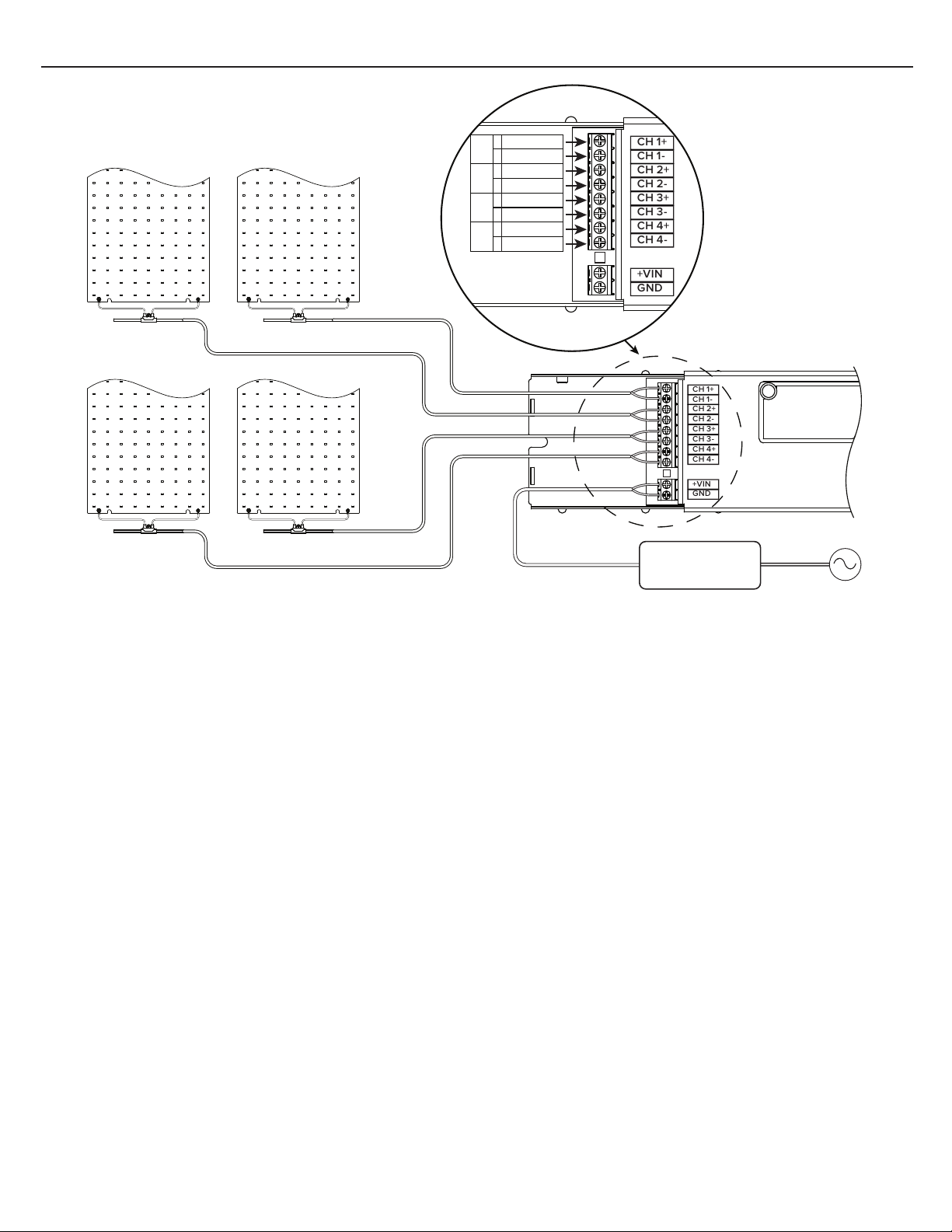
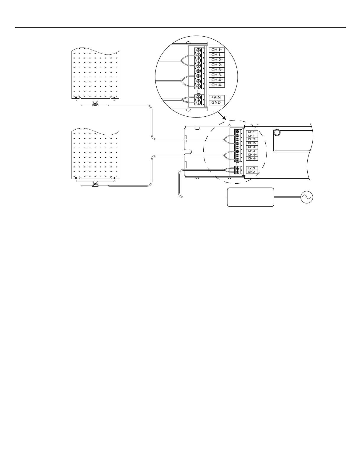
TILE Interior, TILE Exterior, and LINE. There are 4 output channels, each channel can handle up to a 90W load.
For SCT Mode each Output Channel uses 2 x DMX Channels:
1 for DIM Coarse
1 for DIM Fine
In total, each controller occupies 8 x DMX channels, assigned as below:
DMX CH1 – DIM Coarse Output CH1
DMX CH2 – DIM Fine Output CH1
DMX CH3 – DIM Coarse Output CH2
DMX CH4 – DIM Fine Output CH2
DMX CH5 – DIM Coarse Output CH3
DMX CH6 – DIM Fine Output CH3
DMX CH7 – DIM Coarse Output CH4
DMX CH8 – DIM Fine Output CH4
Example of addressing units for SCT LIN Mode on DMX bus:
1. Unit 1 takes DMX Address = 1 and unit occupies DMX Channels # 1-8
2. Unit 2 takes DMX Address = 9 and unit occupies DMX Channels # 9-16
3. Unit 3 takes DMX Address = 17 and unit occupies DMX Channels # 17-24
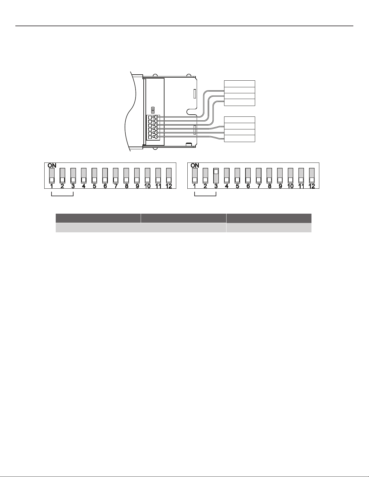
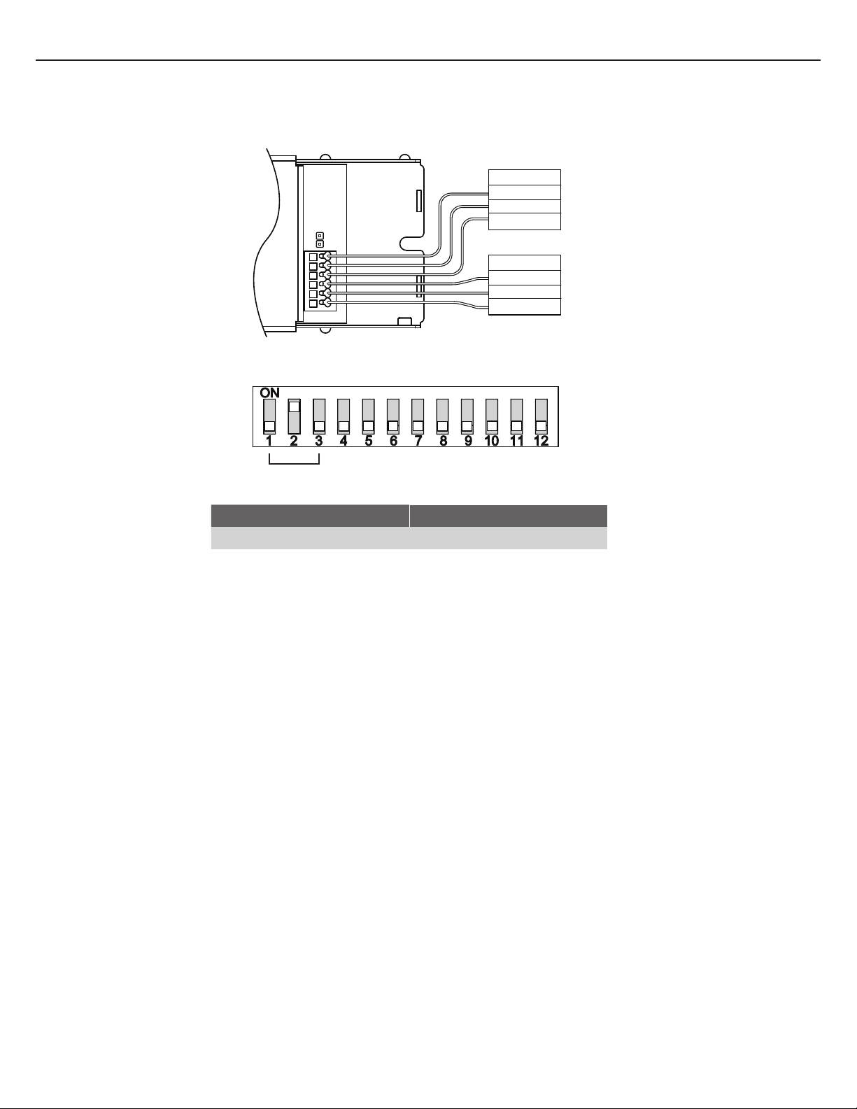
For the above the DIP SETTINGS are:
1. 000 000000001 Controller set for SCT LIN Mode, unit occupies DMX Channels 1-8
2. 000 000001001 Controller set for SCT LIN Mode, unit occupies DMX Channels 9-16
3. 000 000010001 Controller set for SCT LIN Mode, unit occupies DMX Channels 17-24
*Factory set.
DIP switch setting can be adjusted if another dimming curve is required. See APPENDIX A.
Warning! Changing DIP Switch Setting must be performed only after unit is powered down
DMX Cooledge Controller accepts only 16- bit DMX control
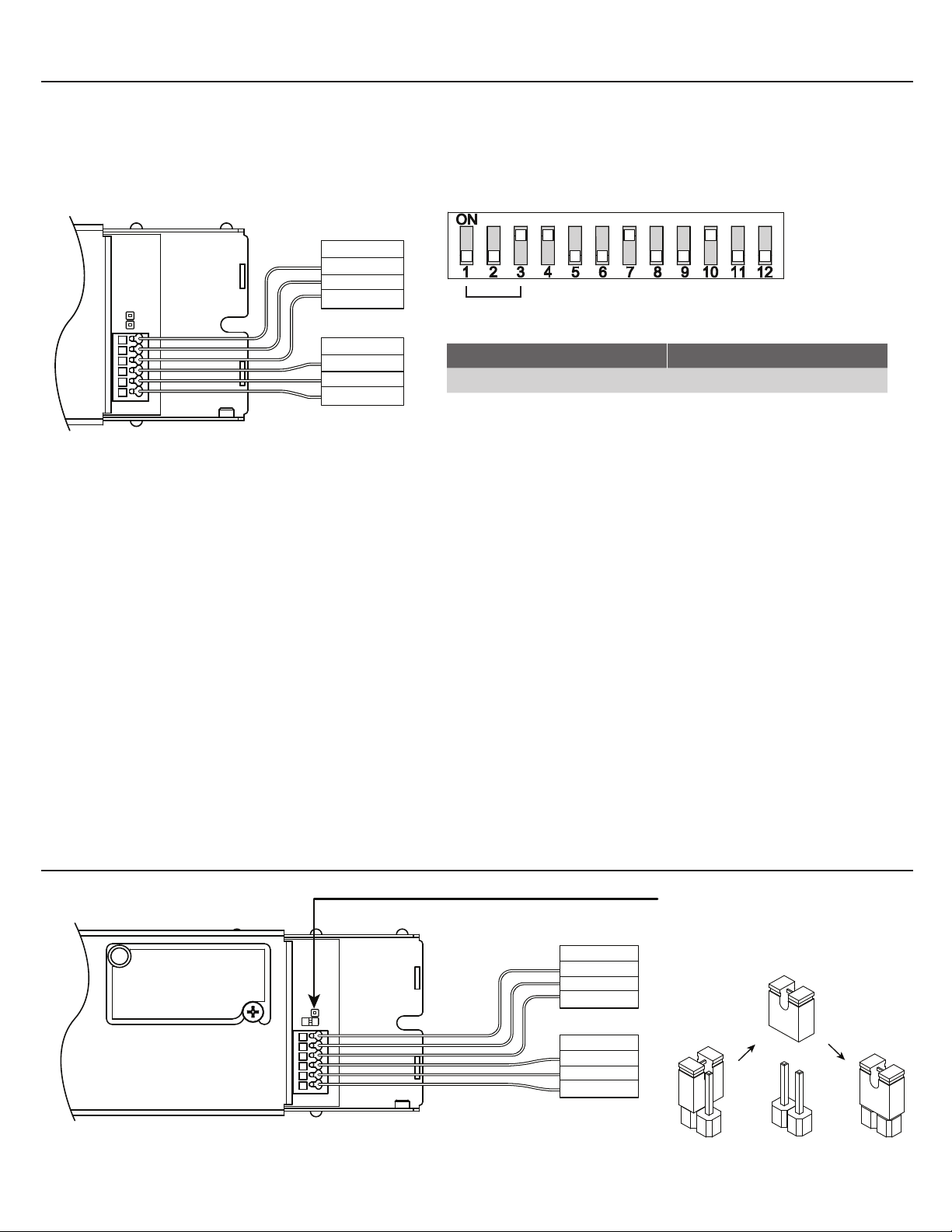
Dimming Protocol Mode Switches 1-3 (Log)* Mode Switches 1-3 (Linear)
DMX SCT 0-0-0 0-0-1
- Switches 1 - 3: Control Module MODE
DMX OUTPUT
GND
D-
D+
DMX INPUT
GND
D-
D+
DMX
LOG MODE LIN MODE