manuals.online logo
Brands
  1. Home
  2. •
  3. Brands
  4. •
  5. turck
  6. •
  7. Control Unit
  8. •
  9. turck FMX-IM-3UR38X User manual

turck FMX-IM-3UR38X User manual

Flow monitoring
For the connection of intrinsically safe flow sensors
IO-Link device with relay outputs
FMX-IM-3UR38X
Edition • 2018-04-09T15:50:43+02:00
1 / 4 TURCK Inc. ñ 3000 Campus Drive Minneapolis, MN 55441-2656 ñ Phone: 763-553-7300 ñ Application Support: 1-800-544-7769 ñ Fax 763-553-0708 ñ www.turck.com
Type designation FMX-IM-3UR38X
Ident-No. 7525103
Operating voltage 20…250VAC
Operating voltage 20…125 VDC
Frequency ï 40…ð 70 Hz
Short-circuit protection yes
Input function Connection of flow sensors
Design Terminal chamber
Dimensions 110 x 27 x 89 mm
Housing material Polycarbonate/ABS
Electrical connection Terminal block
terminals / housing (IEC 60529 / EN 60529)
Packaging unit 1
■Associated equipment [Ex ia Ga / Da]
■Connection of flow probes Zone 0 / 20
■For Ex ia resp. Ex ib sensors
■Relay output for flow, temperature and
faults
■Adjustment of switchpoint, no teaching
of flow boundaries (QuickTeach)
■LED band for indication of flow speed
and media temperature
■Monitoring of operating and display
range
■Detection of wire-break and short-cir-
cuit on the sensor side
■Standard IO or IO-Link operating mode
■Parametrized via pushbutton or soft-
ware-supported via IO-Link
Functional principle
All Ex flow sensors from the FCS series (im-
mersion sensors) and FCI series (inline sen-
sors) can be operated with the FMX-IM exter-
nal processing unit.
The flow module features four status LEDs as
well as a 10-segment LED band for local mon-
itoring. Software-based diagnostic options are
also available to the user, such as wire-break
and short-circuit on the sensor side. Further-
more, monitoring of flow rates and media tem-
peratures within a predefined operating and
display range.
The upper and lower limits of the flow range
are taught in using the max./min. teach mode
implemented. The flow switchpoint is easily
adjusted by means of the Quick-Teach func-
tion, without having to program a lower and
upper limit of the flow range. Working on the
calorimetric principle, the connectible sensors
not only detect the flow rate but also the me-
dia temperature.
The flow module can be operated either in IO-
Link (IOL) or in standard IO (SIO) mode via
the integrated IO-Link interface. In SIO mode,
the switching outputs are operated in the stan-
dard way. In IOL mode the current process
signal is transmitted cyclically as a 10 bit-seri-
al value.
Parametrization is initiated either via pushbut-
ton or software-supported via IO-Link inter-
face. The actual parametrization is then imple-
mented via the tool-based DTM or IODD with-
in the FDT frame PACTware™ or acyclically
near the control via On-Request Data Objects
(ORDO).
Flow monitoring
For the connection of intrinsically safe flow sensors
IO-Link device with relay outputs
FMX-IM-3UR38X
Edition • 2018-04-09T15:50:43+02:00
2 / 4 TURCK Inc. ñ 3000 Campus Drive Minneapolis, MN 55441-2656 ñ Phone: 763-553-7300 ñ Application Support: 1-800-544-7769 ñ Fax 763-553-0708 ñ www.turck.com
Accessories
flow module
FMX-IM-3UR38X
Ident no. 7525103
Wiring Diagram
Accessories
Optionally available:
IO-Link communication line IOL-COM/3M
Connection between FMX-IM (PC Port) and IO-Link master
Ident-no. 7525110
Wiring Diagram
Flow monitoring
For the connection of intrinsically safe flow sensors
IO-Link device with relay outputs
FMX-IM-3UR38X
Edition • 2018-04-09T15:50:43+02:00
3 / 4 TURCK Inc. ñ 3000 Campus Drive Minneapolis, MN 55441-2656 ñ Phone: 763-553-7300 ñ Application Support: 1-800-544-7769 ñ Fax 763-553-0708 ñ www.turck.com
LED display
LED Color Status Description
Pwr green on Operating voltage applied
Device ready for operation
flashing Operating voltage applied
IO-Link communication active
(inverted flash with T on 900 ms and T off 100 ms)
Flow yellow off Switching output flow [low]
on Switching output flow [high]
flashing Teach mode / display of diagnostic data
for specification see manual
Temp yellow off Switching output media temperature [low]
on Switching output media temperature [high]
flashing Teach mode / display of diagnostic data
for specification see manual
Fault red off Switching output fault [high]
on Switching output flow [low]
(for error pattern in combination with LEDs see manual)
For detailed description of the display patterns and flashing codes see instruction manual FM-IM / FMX-IM (D101880)
IO-Link (Process Data Objects)
Bit 15 14 13 12 11 10 9 8 7 6 5 4 3 2 1 0
Flow Value 10 Bit (Bit 15 = MSB, Bit 6 = LSB) not assigned Out 3
(Fault)
Out 2
(Temp)
Out1
(Flow)
Flow monitoring
For the connection of intrinsically safe flow sensors
IO-Link device with relay outputs
FMX-IM-3UR38X
Edition • 2018-04-09T15:50:43+02:00
4 / 4 TURCK Inc. ñ 3000 Campus Drive Minneapolis, MN 55441-2656 ñ Phone: 763-553-7300 ñ Application Support: 1-800-544-7769 ñ Fax 763-553-0708 ñ www.turck.com
Operating manual
Intended use
This device fulfills the directive 2014/34/EC and can be applied in explosion hazardous areas according to EN60079-0, EN60079-11 and
EN61241-11 as associated equipment for connection to intrinsically safe flow sensors.
In order to ensure correct operation to the intended purpose it is required to observe the national regulations and directives.
For use in explosion hazardous areas conform to classification
II (1) G and II (1) D (Group II, Category (1) G, electrical equipment for gas-atmospheres and category (1) D, electrical equipment for dust atmo-
spheres)
Marking (see device or technical data sheet)
É II (1) G [Ex ia Ga] IIC T4 acc. to EN60079-11 and EN60079-0/61241-11 and É II (1) D [Ex ia Da] IIIC
Local admissible ambient temperature
-25…+70 °C
Installation/Commissioning
These devices may only be installed, connected and operated by trained and qualified staff. Qualified staff must have knowledge of protection
classes, directives and regulations concerning electrical equipment designed for use in explosion hazardous areas.
Please verify that the classification and the marking on the device comply with the actual application conditions.
This device is accessory equipment which features intrinsically safe circuits as well as non-intrinsically safe circuits. It may only be installed out-
side the explosion hazardous area in dry, clean and well monitored areas. If a declaration of conformity or declaration of the manufacturer as a
category 3 device exists, the device may be installed in zone 2. Special conditions for safe operation must be observed. Intrinsically-safe elec-
trical equipment can be connected to the intrinsically-safe connections. All equipment must comply with the demands for operation in the exist-
ing zone of the explosion hazardous area. If the intrinsically safe circuits lead to the dust explosion hazardous zones 20 or 21, it is important to
ensure that the devices connected to this circuit fulfil the demands for category 1D or 2D and are certified accordingly. If the equipment is inter-
connected, it is necessary to perform the "Proof of intrinsic safety" (EN 60079-14). Equipment which has been used once to connect intrinsical-
ly safe circuits to non-intrinsically safe circuits is no longer suitable for subsequent use with intrinsically safe circuits. Relevant regulations ex-
ist for the establishment of intrinsically-safe circuits, mounting of external connection parts as well as the characteristics and laying of cables.
Cables and terminals with intrinsically-safe circuits must be marked. They should be separated from non-intrinsically safe circuits or must fea-
ture appropriate insulation (EN 60079-14). Observe the prescribed clearances to earthed components and connections of other devices to the
intrinsically-safe connections of this device. Unless expressed specifically in the device-specific operating instructions, the approval becomes
void if the device is opened, repaired or actions are performed on the device by someone other than approved experts or the manufacturer. Vis-
ible changes to the device housing, such as brown-black discolourations caused by heat, as well as holes or bulges also indicate a serious dan-
ger. Switch off the device immediately. With the associated electrical equipment the interconnected intrinsically-safe equipment must also be
checked. Inspection of a device with regard to the explosion protection can only be performed by an expert or the manufacturer. The operation
of the devices is only permitted in conjunction with the permitted data printed on the side of the housing. Before any commissioning or modifica-
tion of the device interconnections, ensure that the respective regulations, directives and conditions have been complied with and also ensure
that use is only for the intended purpose and the safety requirements have been fulfilled.
After connection to other circuits the sensor may no longer be used in Exi installations. When interconnected to (associated) electrical equip-
ment, it is required to perform the "Proof of intrinsic safety" (EN60079-14).
Installation and mounting instructions
Avoid static charging of cables and plastic devices. Please only clean the device with a damp cloth. Do not install the device in a dust flow and
avoid build-up of dust deposits on the device.
If the devices and the cable could be subject to mechanical damage, they must be protected accordingly. They must also be shielded against
strong electro-magnetic fields.
The pin configuration and the electrical specifications can be taken from the device marking or the technical data sheet.
In order to avoid contamination of the device, please remove possible blanking plugs of the cable glands or connectors only shortly before in-
serting the cable or opening the cable socket.
Special conditions for safe operation
The device must be protected against any kind of mechanical damage.
Service/Maintenance
Repairs are not possible. The approval expires if the device is repaired or modified by a person other than the manufacturer. The most important
data from the approval are listed.
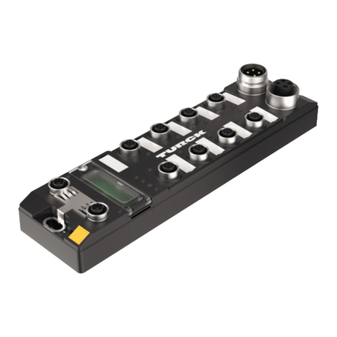
This manual suits for next models

1

Other turck Control Unit manuals

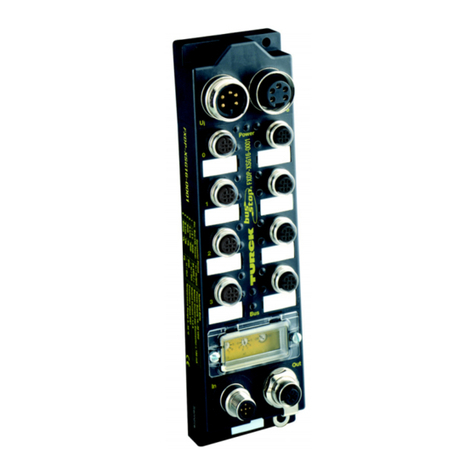
turck TBPN-L FDIO1-2IOL Series User manual

turck

turck TBPN-L FDIO1-2IOL Series User manual

turck TBEN-RFID Series Technical manual

turck

turck TBEN-RFID Series Technical manual

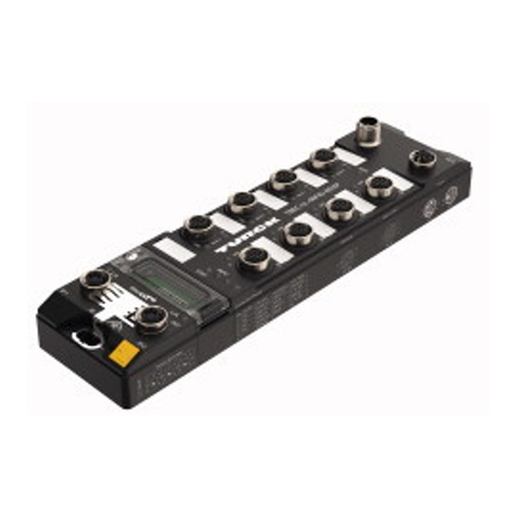
turck TBEN-LH-8IOL User manual

turck

turck TBEN-LH-8IOL User manual

turck FDN-DN1 User manual

turck

turck FDN-DN1 User manual

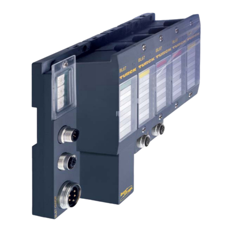
turck BL67 User manual

turck

turck BL67 User manual

turck TBEN-L 8IOL Series User manual

turck

turck TBEN-L 8IOL Series User manual

turck TBPN-L1-FDIO1-2IOL User manual

turck

turck TBPN-L1-FDIO1-2IOL User manual

turck IO-LINK MASTER User manual

turck

turck IO-LINK MASTER User manual

turck excom I/O System Use and care manual

turck

turck excom I/O System Use and care manual

turck TX700 HMI/PLC Series User manual

turck

turck TX700 HMI/PLC Series User manual

turck TBEC-LL-4RFID-8DXP User manual

turck

turck TBEC-LL-4RFID-8DXP User manual

turck FXDP Series User manual

turck

turck FXDP Series User manual

turck TX-EXTEND User manual

turck

turck TX-EXTEND User manual

turck TBEN-S Series User manual

turck

turck TBEN-S Series User manual

turck TBIP-L 4FDI-4FDX Series User manual

turck

turck TBIP-L 4FDI-4FDX Series User manual

turck excom-RMD1-BU User manual

turck

turck excom-RMD1-BU User manual

turck DF20-N User manual

turck

turck DF20-N User manual

turck TBEN-LL-8IOL User manual

turck

turck TBEN-LL-8IOL User manual

turck TBEN-S2-4IOL User manual

turck

turck TBEN-S2-4IOL User manual

turck IM18-CCM51-12I User manual

turck

turck IM18-CCM51-12I User manual

turck TBEN EN1 Series User manual

turck

turck TBEN EN1 Series User manual

turck TBEN-Lx-8IOL User manual

turck

turck TBEN-Lx-8IOL User manual

Popular Control Unit manuals by other brands

Link 600 Series installation instructions

Link

Link 600 Series installation instructions

HBK TIM-PN Mounting instructions

HBK

HBK TIM-PN Mounting instructions

Metso MAPAG Butterfly valve Type A Installation maintenance and operating instructions

Metso

Metso MAPAG Butterfly valve Type A Installation maintenance and operating instructions

Schlumberger CAMERON AOP D2 Series Installation, operation and maintenance manual

Schlumberger

Schlumberger CAMERON AOP D2 Series Installation, operation and maintenance manual

Aqara Hub manual

Aqara

Aqara Hub manual

Huawei UPS5000-H-400K-NT user manual

Huawei

Huawei UPS5000-H-400K-NT user manual

Lintec CV-1000 Series instruction manual

Lintec

Lintec CV-1000 Series instruction manual

Franklin Electric SUBDRIVE CONNECT Series Installation and operation manual

Franklin Electric

Franklin Electric SUBDRIVE CONNECT Series Installation and operation manual

M-system R7M-EC8C instruction manual

M-system

M-system R7M-EC8C instruction manual

Trane TR200 MCB 101 operating instructions

Trane

Trane TR200 MCB 101 operating instructions

Laird SSD40NBT Hardware integration guide

Laird

Laird SSD40NBT Hardware integration guide

Panasonic HIT VBHN340SA17E General installation manual

Panasonic

Panasonic HIT VBHN340SA17E General installation manual

dtm WL2 Assembly and operating manual

dtm

dtm WL2 Assembly and operating manual

Pro-Log SERIES 90 operating instructions

Pro-Log

Pro-Log SERIES 90 operating instructions

Viking G-2000P Technical data

Viking

Viking G-2000P Technical data

Pepperl+Fuchs SC4-2 instruction manual

Pepperl+Fuchs

Pepperl+Fuchs SC4-2 instruction manual

Lutron Electronics GRAFIK Eye QSGRJ-3P Installation and operation guide

Lutron Electronics

Lutron Electronics GRAFIK Eye QSGRJ-3P Installation and operation guide

Honeywell DIAL-SET DS05C Product data

Honeywell

Honeywell DIAL-SET DS05C Product data

manuals.online logo
manuals.online logoBrands
  • About & Mission
  • Contact us
  • Privacy Policy
  • Terms and Conditions

Copyright 2025 Manuals.Online. All Rights Reserved.