manuals.online logo
Brands
  1. Home
  2. •
  3. Brands
  4. •
  5. Alarmtech
  6. •
  7. Security Sensor
  8. •
  9. Alarmtech MC 340 2x4,7k User manual

Alarmtech MC 340 2x4,7k User manual

MC 340_2R Instruction Manual 4-MC340_2R-01
© 2021 Alarmtech Rev. MC340_2R_2123en Page 1of 2
Detectors
Magnetic Contact
Recessed mounting
Instruction Manual MC 340 2x4,7k / 2x16,2k
DESCRIPTION
MC 340 with built-in resistors is a versatile magnetic contact
used in both alarm and security access control systems for
protection of doors, gates and windows against
unauthorized opening. A wide range of accessories enables
the contact to be recessed- or surface-mounted on a variety
of surfaces, including ferromagnetic materials.
MOUNTING INSTRUCTIONS
Contact and magnet should be installed axially,
corresponding to each other.
Catch-bolts on the housing enable direct installation in
ф8 mm holes in wood.
Appropriate accessory must be used for installation in
ferromagnetic environment.
CIRCUIT DIAGRAM
DISTANCE DIAGRAM - WOOD
TECHNICAL DATA
Working environment
Wood
Steel
Make distance
typ. 21 mm ±40 % 1)
see distance table
Break distance
typ. 25 mm ±40 % 1)
see distance table
Contact type
form A, SPST
Switching voltage max.
48 V DC/AC
Switching current max.
500 mA DC/peak AC
Contact rating max.
10 W
Cable
ф 2,8 mm, 2x0,182 mm2
Environmental class
EN 50130-5:2011 Class IIIA
VdS 2110:2017-09 Class III
SSF 1014-5 Class III
Operating temperature range
-40°C to +70°C
Operating humidity range
max. 95% r. h.
Housing material
plastic ABS
IP protection class
IP 67
Dimensions, Contact part
ф 8 x 26 mm
Dimensions, Magnet part
ф 8 x 26 mm
Security grade
EN 50131-2-6:2008 Grade 2, VdS 2120:2011-06 Class B
SSF 1014-5 Grade 2
Approvals
VdS - G100508
1) Make distance is always shorter than break distance
0
5
10
15
20
25
30
-25 -15 -5 515 25
y [mm]
x [mm]
Make distance Break distance
MC 340_2R Instruction Manual 4-MC340_2R-01
© 2021 Alarmtech Rev. MC340_2R_2123en Page 2of 2
OPERATING PRINCIPLE
MC 340 magnetic contact has two parts: the contact part
with a reed switch and the magnet part. In its neutral
position the reed switch remains closed under the force of
the magnetic field. Opening the monitored object increases
the distance between the reed switch and the magnet. This
reduces the influence of the magnetic field on the reed
switch until it opens and activates an alarm.
Magnetic contacts should not be installed in the vicinity of
strong magnetic fields.
INSTALLATION
Contact and magnet should be aligned axially in the frames
and leaves of the monitored objects (windows, doors etc.).
Offset will reduce the working distances. The contact should
be mounted in the stationary part of the monitored object
(ex. door frame) and the magnet in the movable part (ex.
door leaf). Before mounting, holes must be drilled. Catch-
bolts on the housing enable direct installation in ф8 mm
holes in wood.
For sites where it is impossible to mount the contact
directly, a variety of accessories is available.
Accessories with a strong magnet provide a bigger working
distance for more demanding applications and maintain the
parameters of the magnetic contact when mounted in
ferromagnetic environment.
Accessories for surface mounted applications provide
installation solutions for sites where recessed mounting is
not suitable.
The working distances of the magnetic contact will be
decreased in the proximity of ferromagnetic surfaces. The
closer the contact/magnet is installed to the ferromagnetic
surface, the lower the working distances
Only non-ferromagnetic screws may be used when mounting
the contact using accessories.
After the installation, use an ohmmeter to check the
electrical connections and test the function of the magnetic
contact.
Warning: applying excessive force to the housing of the
contact may damage the glass body of the reed switches
inside.
Warning: appropriate accessories must be used for
installation in ferromagnetic environment.
DISTANCE TABLE
Contact
Accessory
Distance on wood [mm]
Distance on steel [mm]
Make
Break
Make
Break
MC 340
-
21
25
X
X
MC 300-S1
21
25
X
X
MC 300-S3
17
20
12a)
15a)
MC 300-S11
21
25
X
X
MC 300-S12
35
40
22
24
MC 300-S21
21
25
X
X
MC 300-S22
35
40
27
30
MC 300-S31
21
25
X
X
MC 300-S32
35
40
22
24
MC 300-S35
18
20
X
X
X –not recommended
a) measured with spacers (included in the MC 300-S3 set)
We reserve the right to changes without notice.We reserve the right to changes without notice.

This manual suits for next models

1

Other Alarmtech Security Sensor manuals
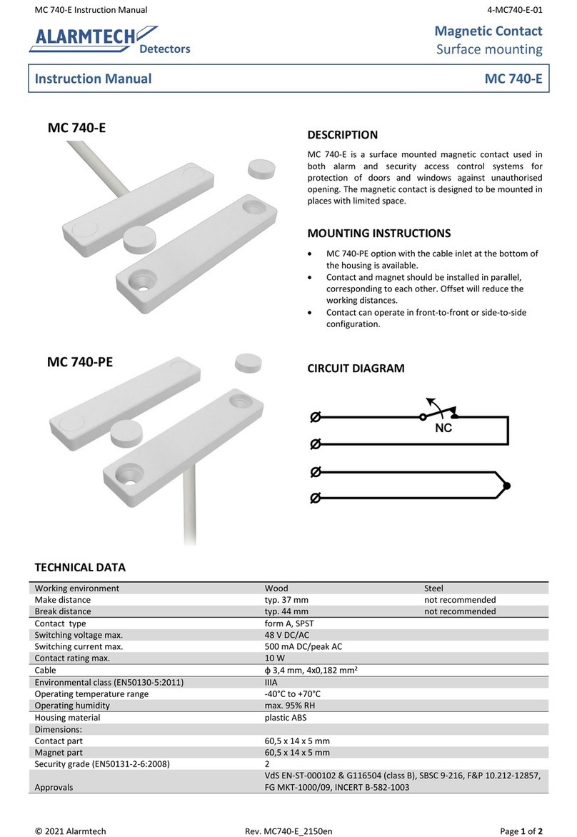
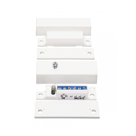
Alarmtech MC 472 User manual

Alarmtech

Alarmtech MC 472 User manual

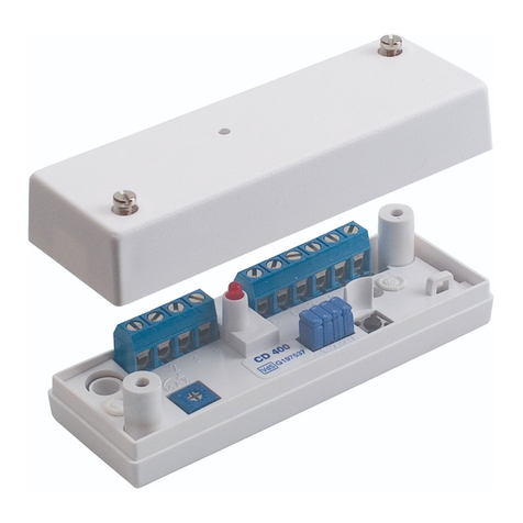
Alarmtech CD 400 User manual

Alarmtech

Alarmtech CD 400 User manual

Alarmtech MC 140 User manual

Alarmtech

Alarmtech MC 140 User manual

Alarmtech AD 800 Manual

Alarmtech

Alarmtech AD 800 Manual

Alarmtech MC 740-E User manual

Alarmtech

Alarmtech MC 740-E User manual
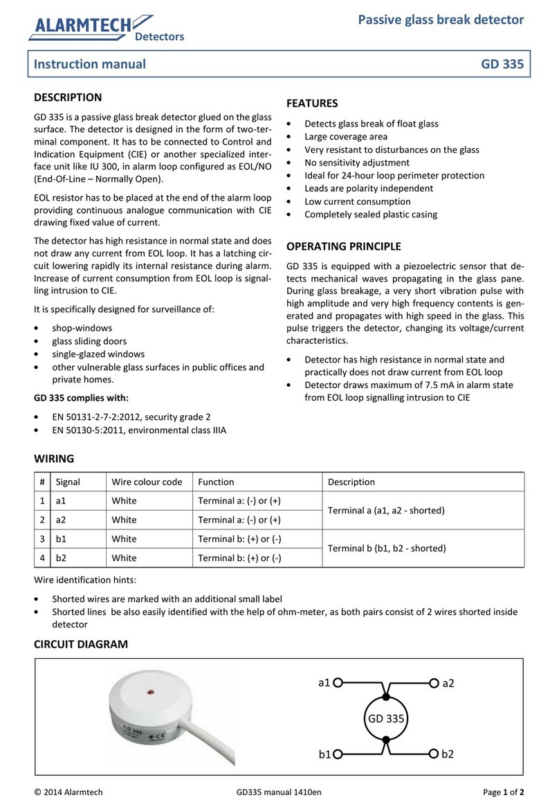
Alarmtech MC 740-E-M14 User manual

Alarmtech

Alarmtech MC 740-E-M14 User manual

Alarmtech MC 346 User manual

Alarmtech

Alarmtech MC 346 User manual

Alarmtech CD 470-I User manual

Alarmtech

Alarmtech CD 470-I User manual

Alarmtech CD 470 User manual

Alarmtech

Alarmtech CD 470 User manual

Alarmtech CD 470 User manual

Alarmtech

Alarmtech CD 470 User manual

Alarmtech GD 375 Instruction Manual

Alarmtech

Alarmtech GD 375 Instruction Manual

Alarmtech AD 700 User manual

Alarmtech

Alarmtech AD 700 User manual

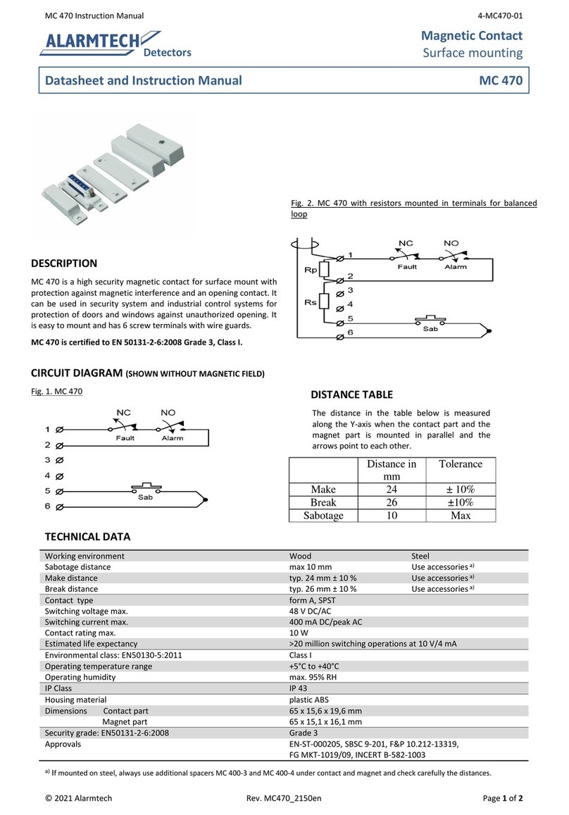
Alarmtech MC 470 User manual

Alarmtech

Alarmtech MC 470 User manual

Alarmtech GD 335 User manual

Alarmtech

Alarmtech GD 335 User manual
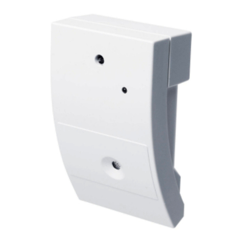
Alarmtech AD 800-AM Manual

Alarmtech

Alarmtech AD 800-AM Manual

Alarmtech MC 740-E User manual

Alarmtech

Alarmtech MC 740-E User manual
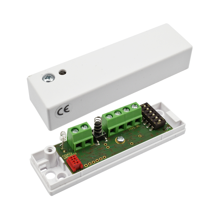
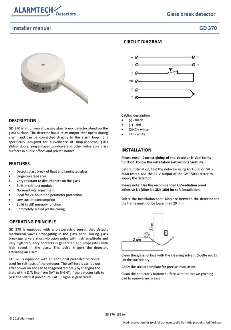
Alarmtech GD 370 User guide

Alarmtech

Alarmtech GD 370 User guide
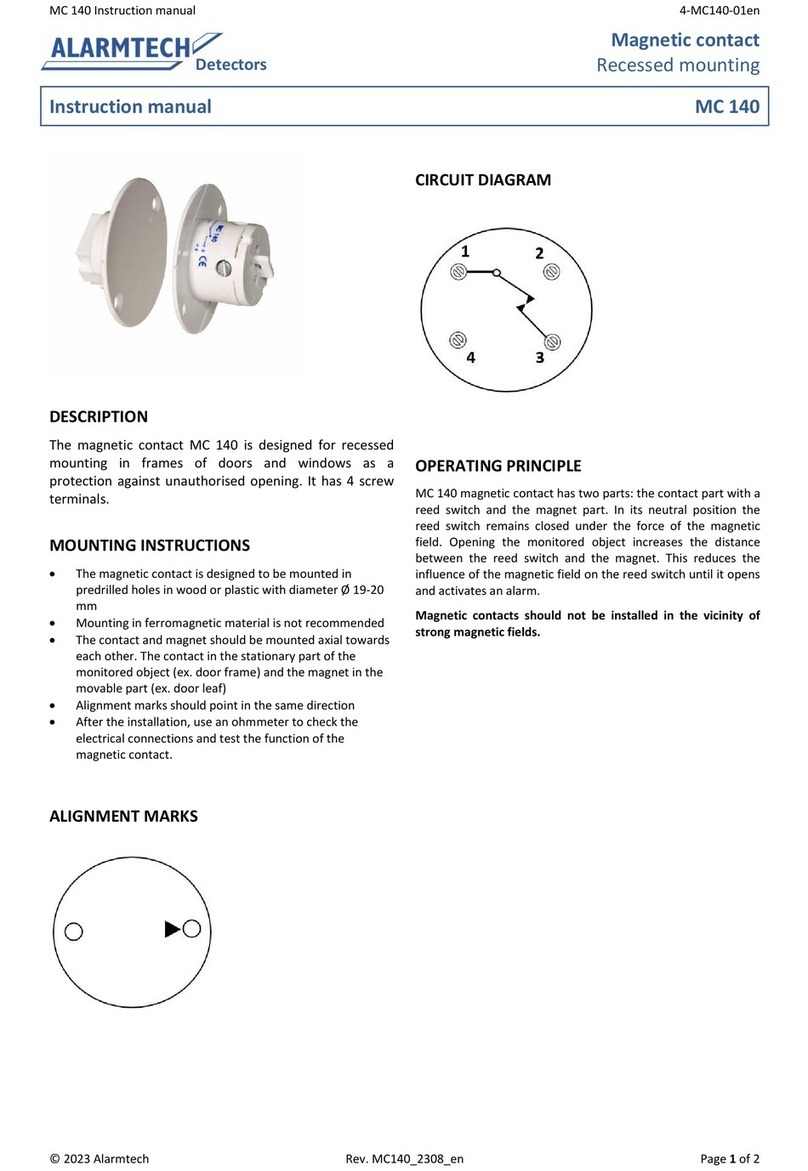
Alarmtech MC 746-E User manual

Alarmtech

Alarmtech MC 746-E User manual
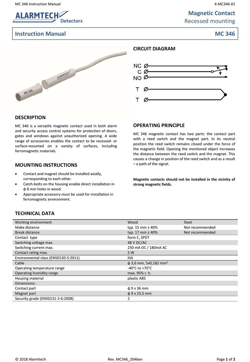
Popular Security Sensor manuals by other brands

Gardigo 60035 operating instructions

Gardigo

Gardigo 60035 operating instructions

RKI Instruments 35-3001A-02 Operator's manual

RKI Instruments

RKI Instruments 35-3001A-02 Operator's manual

Evikon PluraSens E2638-LEL user manual

Evikon

Evikon PluraSens E2638-LEL user manual

Smart Bridge 9500N-100 Quick install guide

Smart Bridge

Smart Bridge 9500N-100 Quick install guide

EINHELL TC-MD 50 Original operating instructions

EINHELL

EINHELL TC-MD 50 Original operating instructions

Atal AT-VLC-ND-A2-RS user manual

Atal

Atal AT-VLC-ND-A2-RS user manual

Honeywell ADEMCO 5808EU installation instructions

Honeywell

Honeywell ADEMCO 5808EU installation instructions

Wenglor I08G003 operating instructions

Wenglor

Wenglor I08G003 operating instructions

HP 423A Operating note

HP

HP 423A Operating note

jablotron JA-158P quick start guide

jablotron

jablotron JA-158P quick start guide

Waeco Multi Gas operating manual

Waeco

Waeco Multi Gas operating manual

Extech Instruments DV40 manual

Extech Instruments

Extech Instruments DV40 manual

systemax Poolnanny installation guide

systemax

systemax Poolnanny installation guide

C-LOGIC 520-PC instruction manual

C-LOGIC

C-LOGIC 520-PC instruction manual

SENKO SP12C7 operating manual

SENKO

SENKO SP12C7 operating manual

SENSOR MAESTROS SFM2 user manual

SENSOR MAESTROS

SENSOR MAESTROS SFM2 user manual

Waytronic MicroSound V3.11 quick start guide

Waytronic

Waytronic MicroSound V3.11 quick start guide

ESA Corona CAD Operating and maintenance manual

ESA

ESA Corona CAD Operating and maintenance manual

manuals.online logo
manuals.online logoBrands
  • About & Mission
  • Contact us
  • Privacy Policy
  • Terms and Conditions

Copyright 2025 Manuals.Online. All Rights Reserved.