Cooper Security Scantronic 734r Series User manual

1
734r EN
NL
Fr
It
Dk
N
Sv
De
Es
Pt

2
Part No. 497361 Issue 1
This product complies with the requirements of European Directive: 1995/5/EC (Radio
&Telecommunications Terminal Equipment Directive).

3
Fig. 1
Magnet
Magneet
Aimant
Magnete
Magnet
Magnet
Magnet
Activity LED
Activiteiten LED
LED d’activité
LED Attività
Aktivitets LED
Aktivitets LED
Aktivitets LED
Cover screw
Deksel schroef
Vis du capot
Vite Coperchio
Dælselskrue
Kåpskruv
Dekselskrue

4
Fig. 2
NL
1. Montagegat
2. Sabotagestrip
3. Kabeldoorvoer
4. Montagegat
5. Antenne
6. LED
7. Zender
8. Batterijhouder
9. Sab. schak.
10. Aansluitblok:
5-weg op model -00
2-weg op model -01
11. Link 4,2
12. Reed Switch
13. Link 1,3
UK
1. Fixing hole
2. Tamper bar
3. Cable entry
4. Fixing hole
5. Antenna
6. LED
7. Transmitter
8. Battery holder
9. Tamper switch
10. Connector blocks
5-way on -00 version
2-way on -01 version
11. Link 4,2
12. Reed Switch
13. Link 1,3
Fr
1. Trou de fixation
2. Barre d’auto-protection
3. Passage de câble
4. Trou de fixation
5. Antenne
6. LED
7. Emetteur
8. Pile
9. Contact d’auto-protection
10. Bornier de raccordement :
- 5 bornes (version -00)
- 2 bornes (version -01)
11. Cavaliers (LK4,LK2)
12. Contact Reed
13. Cavaliers (LK1,LK3)
Dk
1. Monteringshul
2. Sabotagearm
3. Kabelindgang
4. Monteringshul
5. Antenne
6. LED
7. Sender
8. Batteriholder
9. Sabotagekontakt
10. Tilslutningsblok:
(5-vejs på -00 version, tovejs
på -01 version)
11. Link 4,2
12. Reedafbryder
13. Link 1,3
Sv
1. Monterings hål
2. Sabotagehinder
3. Kabelintag
4. Monterings hål
5. Antenn
6. LED
7. Sändare
8. Batterihållare
9. Sabotagekontakt
10. Kopplingsblock:
(5-vägars på -00 version,
2-vägars på -01 version)
11. Länk 4,2
12. Läs Kontakt
13. Länk 1,3
N
1. Monteringshull
2. Sabotasjearm
3. Kableinngang
4. Monteringshull
5. Antenne
6. LED
7. Sender
8. Batteriholder
9. Sabotasjebryter
10. Tilslutningsblokk:
-5 veis på -02 versjon,
-2 veis på -01 versjon
11. Link 4,2
12. Reedbryter
13. Link 1,3
It
1. Vite di fermo
2. Tamper Anti Strappo
3. Entrata Cavi
4. Foro Fissaggio
5. Antenna
6. LED
7. Transmettitore
8. Alloggiamento Batteria
9. Tamper Apertura
10. Morsetti:
5 morsetti (vers. -00 )
2 morsetti (vers. -01)
11. Link 4,2
12. Reed Interno
13. Link 1,3

5
Fig. 3
LK1 LK3
1
2
3
4
=
Link fitted
Met Brug
Cavalier en place
Chiuso
Link Monteret
Länk Anpassad
Link Monteret
=
Link not fitted
Zoneder Brug
Cavalier retire
Aperto
Link Fjernet
Länk ej passad
Link fjernet
UK
1 = Roller Shutter
2. = Shock Sensor
3. = Normally Closed
4. = Normally Open
NL
1. = Rolluik
2. = Schokdetector
3. = Normaal Gesloten
4. = Normaal Geopend
Fr
1. = Volet Roulant
2. = Detecteur de choc
3. = Normalement ferme
4. = Normalement overt
It
1. = Contatto Fune
2. = Inerziale
3. = Contatto NC
4. = Contatto NA
Dk
1. = Rullejalousi
2. = Stødsensor
3. = Hvilekontakter
4. = Arbejdskontakter
N
1. = Rullkontakt
2. = Shocksensor
3. = Normalt stängd
4. = Normalt öppen
Sv
1. = Rullejalousi
2. = Støtsensor
3. = Hvilekontakter
4. = Arbeidskontakter

6
Fig. 4

7
Fig. 5
1
4545
3
22
1. Extension sensor zone 1
Aansluiting sensor zone 1
Detecteur externe zone 1
Sensore esterno canale 1
Forlængelse af sensor zone 1
Förlängnings sensor zon 1
Forlengelse av sensor zone 1
2. External sensor zone 2
Externe detector zone 2
Detecteur externe zone 2
Sensore esterno canale 2
Ekstern sensor zone 2
Extern sensor zon 2
Ekstern sensor sone 2
3. Link if not using extension sensor zone 1
Plaats brug als u zone 1 niet gebruikt
Strapper ces 2 borne si aucun detecteur externe n’est pas
utilise pour la zone 2
Chiuddere se non si utilizza l’ingresso esterno per canale 1
Link vis der ikke benyttes forlængelse af sensor zone 1
Länk utan anv. av förlängnings sensor
Link hvis det ikke benyttes forlengelse av sensor sone 1
4. Alarm
Alarme
Alarm
Allarme
Alarm
Larm
Alarm
5. Tamper
Sabotage
Autoprotection
Tamper
Sabotage
Sabotagekontakt
Sabotasje

8
1. External sensor zone 2
Exteerne detector zone 2
Detecteur externe zone 2
Sensore esterno canale 2
Ekstern sensor zone 2
Extern sensor zon 2
Ekstern sensor sone 2
2. Alarm
Alarm
Alarme
Allarme
Alarm
Larm
Alarm
3. Tamper
Sabotage
Autoprotection
Tamper
Sabotage
Sabotagekontakt
Sabotasje
4. Note: Voltage free contact only.
Remarque : contacts libres de toute tension uniquement
Nota: Solo contatti pulitti
N.B! Kun spændingsfrie kontakter
OBS: Strömfria kontakter endast
NB: Bare spenningsfrei Kontakter
Yellow, Geel, Jaune, Giallo, Gul
Violet, Viola, Fiolett, Violett
Red, Rood, Rouge, Rosso, Rød, Röd
Gold, Goud, Or, Oro, Gylden, Guld, Gullen
4k7
2k2
Fig. 6

9
EN
Introduction
The 734rEUR-00 and -01 transmitters are designed to work with any Scantronic 868MHz
narrow band receiver. Both variants are two zone multi-function transmitters designed for
use in any of the following applications:
a) On their own as door contacts, using the supplied magnet.
b) With a suitable external sensor to signal the opening of roller shutters by a set amount
(-00 version only).
c) With an external shock sensor to signal the presence of vibrations above a
programmed level (-00 version only).
d) With any voltage free contacts.
When used with both internal reed switch and external sensors the transmitter takes up
two zones (or channels) on the receiver.
The external connector on the -00 variant is designed for four wire closed circuit sensors.
The -01 variant is designed for Fully Supervised Loop (FSL) sensors.
In both variants the case is protected by an internal back tamper switch and an internal lid
tamper switch.
Opening the Case
Open the transmitter by undoing the cover screw and lifting the front away (see Fig.1). Fig-
ure 2 shows the main internal features of the transmitter.

10
Controls and Indicators
The main printed circuit board (pcb) contains the following controls and indicators:
LED Continuous flashing: Programming mode (-00 version only).Flashing in groups of
four: transmission. Off: normal operation.
LK1 Mode jumper (-00 version only). Link fitted: LK3 selects N/O or N/C for external
switches connected to Alarm contacts. Link not fitted: LK3 selects either roller
shutter or shock sensor.
LK3 (-00 verson) Selector, works in conjuction with LK1.(-01 version) LED enable.
Figure 3 shows how LK1 and LK3 work together for the -00 version.
LK2 Link fitted: disable internal reed switch.
LK4 Programming. Link fitted: program roller shutter extension or shock sensor vibration
level. Link not fitted, normal operation.
Specification
Part No. 734rEUR-00, 734rEUR-01
Power Supply 3V CR2 Li/MnO2 battery
Battery Life Approximately 14 months
Temperature Range -10 to +55 °C
Low voltage alarm 2.4V nominal
Environmental Class I (Tested -10 to +55°C)
Security Grade II
INCERT No C0160194

11
EN
Installation
Siting
Do NOT mount the unit:
Near the floor.
Close to or on large metal structures.
Closer than one meter to mains wiring and metal water or gas pipes.
Inside steel enclosures.
Next to electronic equipment, particularly computers, photocopiers or other radio
equipment.
Upside down or on its side.
Door Contact
Where possible mount the body of the transmitter close to the top of the non-moving frame
of a door or window, and the magnet on the moving part (see Figure 4). If the frame is not
wide enough, mount the magnet on the frame and the body on the moving part.
DO:
Make sure there is less than 10mm between magnet and transmitter body with the
door/window closed.
Make sure the magnet aligns with the reed switch with the door/window closed.
Do NOT mount the unit on the hinged edge of the door.

12
Preparing for Installation
Open the case by removing the cover screw and pivoting the cover up from the bottom.
Remove the pcb by undoing the screw and lifting the pcb clear from the top. Slide the pcb
up out of the pcb bracket. Install one 3V CR2 Li/MnO2 battery in the battery holder on the
pcb.
Learning
Each transmitter provides two separate zones. You can make the receiver learn each zone
independently. Make sure the receiver is in learn mode (see the Installation and Program-
ming Guide for the receiver) before starting.
Learning Zone 1
First make sure both back and lid tamper switches are closed, then trigger either the lid or
back tamper.
Learning Zone 2 - 00 version
Fit a plain wire shorting link to the tamper terminals on the connector block. Open the link
to cause a transmission.
Learning Zone 2 - 01 version
Fit a 2k2 resistor to the terminals on the connector block. Open the link to cause a trans-
mission.
Alternatively, wire in an external sensor as shown on the next page and open the tamper
switch.

13
EN
For receivers that use infra-red learn hold the transmitter’s activity LED no more than
50mm away from the infra-red learn sensor on the receiver.
Physical Installation
Mount the back
1. Remove the PCB from the case back.
2. Hold the back in the chosen location.
3. Mark two holes through the fixing slots in the back.
4. Secure the back to the surface using two Type ‘C’ 15mm Domehead screws.
5. Make sure the back is flush against the surface and pushes the tamper bar in far
enough to activate the tamper switch.
6. Re-fit the PCB into the back of the case.
7. If you are using the internal reed switch then mount the external magnet at a suitable
point on the door or window being protected.
NOTE: If you plan to use the internal reed switch OR zone 1 then YOU MUST REMOVE
THE JUMPER FROM LK2. (If you wish to retain the jumper link then fit it onto one pin
only.)
Connecting External Door Contacts or N.C. Switches
You can wire external Normally Closed devices (for example the 20mm Quikfit) to the 734r
transmitter. You may connect several contacts in series, but the alarm control unit will treat
them all as one zone. Do not use more than 10m total cable length from the 734r to the
last external contact

14
Both variants of the 734r provide two zones. However, connections to the zones differ
between variants.
In the -00 variant the internal reed switch and the two left hand terminals on the connector
block both provide alarm contacts for zone 1. The lid tamper provides the tamper contacts
for zone 1. The four right hand terminals provide alarm and tamper connections for zone 2.
In the -01 variant the internal reed switch and lid tamper provides zone 1. The two FSL
terminals on the connector block provide both alarm and tamper for zone 2.
Connections for -00 Variant
1 . Remove any wire links from the Alarm and Tamper terminals.
2. Connect Normally Closed contacts wired as shown in Figure 5.
If you wish to connect Normally Open switches then fit links to LK1 and LK3, as shown in
Figure 3.
Wiring a Roller Shutter or Shock Sensor
When connecting the transmitter to roller shutter or shock sensors, connect the alarm
contacts of the sensor to the terminals marked “Alarm”. If present, connect the tamper con-
tacts of the sensor to the terminals marked “Tamper”. If the sensor does not have tamper
contacts:
EITHER a) Connect a spare pair of wires in the cable to the Tamper terminals and short
circuit the far end of the pair.
OR b) Fit a wire link to short circuit the Tamper terminals in the transmitter.

15
EN
Connections for -01 Variant
The 734rEUR-01 provides two terminals for FSL circuits. Fit a 2k2 resistor at the end of the
detector loop in series with the tamper contacts of the sensor, and a 4k7 resistor in parallel
with the alarm contacts of the sensor, see Figure 6.
Commissioning
Selecting Operating Mode
To use the 734r with a shock- or roller shutter sensor make sure that link LK1 is open
circuit (jumper NOT fitted).
Programming
When using the 734r as a roller shutter detector or as a shock sensor then you may pro-
gram the detector’s sensitivity to events. To enter programming mode short circuit LK4 by
fitting a jumper over both pins. The activity LED flashes continuously while the transmitter
is in programming mode. To leave programming mode remove the short circuit from LK4
by fitting the jumper to one pin only. Note that you do not need to program the 734r when
using it as a door contact.
Note: If the 734r refuses to enter programming mode (LED does not flash continuously)
then the battery may be low. Change the battery and try again.
Roller Shutter
When using the 734r with a roller shutter sensor you can program the transmitter to

16
transmit an alarm after a set number of open/close events on the roller shutter sensor. By
default the 734r will send an alarm after detecting six closures on the sensor. To change
this number:
1. Place the transmitter in programming mode.
2. Operate the roller shutter sensor for the required number of open/close events. (Make
sure that all the open/close events occur within 20 seconds.)
3. Leave programming mode.
The transmitter will now signal an alarm condition after the programmed number of open/
close events.
Shock Sensor
When using the 734r with a shock sensor you can program the minimum level of shocks
that the transmitter will respond to.
1. Place the transmitter in programming mode.
2. Vibrate the shock sensor with smallest level of force that you wish the transmitter to re-
spond to (strike the wall or door on which the sensor is mounted). Activate the sensor
repeatedly four or five times.
3. Leave programming mode.
The transmitter will now ignore any shocks smaller than the average of those you used
during programming.
Enabling/Disabling the LED (-00 version)
You can select whether the Activity LED operates or not during radio transmissions. To
enable the LED:

17
EN
1. Make sure transmitter is not in programming mode (no jumper on LK4).
2. Fit one jumper to the LK1 pins, and fit another to the LK3 pins.
3. Momentarily fit a jumper to the LK4 pins and then remove it.
The LED will now flash for all types of transmission except supervision, unless the battery
is low.
To disable the LED:
1. Make sure transmitter is not in programming mode (no jumper on LK4).
2. Fit one jumper to the LK1 pins only.
3. Momentarily fit a jumper to the LK4 pins and then remove it.
The Activity LED will not flash for any transmission. Note that the LED will also not flash to
indicate low battery.
Enabling/Disabling the LED (-01 version)
To enable the Activity LED fit LK3.
To disable the Activity LED remove LK3.
Testing.
1. Put the control unit into engineer walk test.
2. Trigger the transmitter.
3. Make sure the panel receives the alarm.
4. Chose another site for the transmitter if the panel does not receive the signal.
6. Press X on the control panel when you have finished testing, to stop the walk test.

18
© Cooper Security Limited 2004
Every effort has been made to ensure that the contents of this leaflet are correct . How-
ever, neither the authors nor Cooper Security Limited accept any liability for loss or dam-
age caused or alleged to be caused directly or indirectly by this leaflet. The contents of this
leaflet are subject to change without notice.
Printed and published in the U.K.

19
NL
Introductie
De zenders 734rEUR-00 en -01 zijn ontwikkeld voor Scantronic 868MHz smalle band
ontvangers. Beide uitvoeringen zijn multifunctionele zenders met twee zones. Hieronder
volgen enkele toepassingen:
a) Met bijgeleverde magneet: zelfstandig deurcontact.
b) Met externe sensor: signaleren van het openen van rolluiken en overhead deuren.
c) Met externe schokdetector: signaleren van vibraties.
d) Met spanningsvrije contacten: toepassing naar keuze.
Indien zowel de interne reed-schakelaar als een externe sensor wordt toegepast gebruikt
de zender twee zones of kanalen van de ontvanger.
De externe aansluiting van de -00 versie is geschikt voor sensoren met een vier-draads
gesloten circuit. Versie -01 is geschikt voor FSL sensoren.
In beide gevallen is de behuizing beveiligd tegen sabotage met een schakelaar tegen de
muur en een schakelaar tegen het front.
De behuizing openen
Open de behuizing door de dekselschroef los te draaien en de deksel af te nemen. Afbee-
lding 2 toont de belangrijkste interne onderdelen van de zender.

20
Controle en indicatie
Op de PCB-kaart ziet u de volgende controle- en indicatiemiddelen:
LED Continu brandend: Programmeerstand (alleen -00). Knippert in blokken van vier:
Verzending. Uit: Standaard werking.
LK1 (Alleen -00.) Brugschakelaar voor mode. Met brug: LK3 kiest externe N/O of N/C
schakelaar. Zonder brug: LK3 kiest rolluik- of schokdetector.
LK3 Model-00: Keuze schakelaar in combinatie met LK1. Model -01: Activiteiten LED
aan/uit
Afbeelding 3 toont de schakelingen van model -00.
LK2 Met brug: Interne reedschakelaar uitgeschakeld.
LK4 Programmeren: Met brug: programmeer rolluik- of schokdetector. Zonder brug:
Standaard werking.
Specificaties
Artikelnummer 734rEUR-00, 734rEUR-01
Voeding 3V CR2 Li/MnO2 batterij.
Levensduur batt. Ongeveer 14 maanden.
Temperatuur -10 tot +55 °C.
Melding spanning laag 2,4V nominaal.
This manual suits for next models
2
Table of contents
Languages:
Other Cooper Security Transmitter manuals
Cooper Security
Cooper Security Scantronic 735r User manual

Cooper Security
Cooper Security 726r User manual
Cooper Security
Cooper Security 702r User manual
Cooper Security
Cooper Security 4601-50 User manual

Cooper Security
Cooper Security 706r User manual
Cooper Security
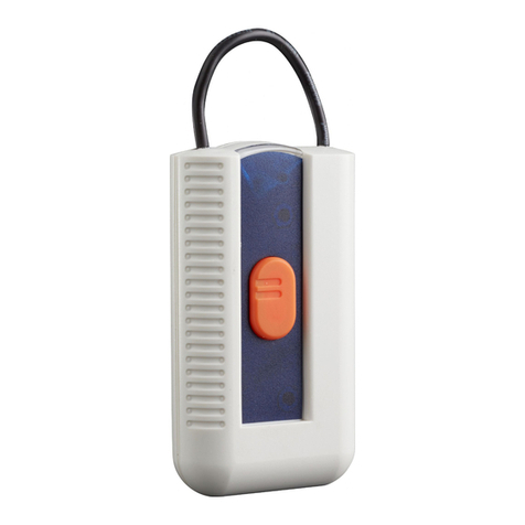
Cooper Security Scantronic 701REUR-50 User manual