7
MP6600 Series
Installation Instructions
Multi-Point Lock
FM524 02/20
Copyright © 2019, 2020 ASSA ABLOY Access and Egress Hardware Group, Inc. All rights reserved. Reproduction in whole
or in part without the express written permission of ASSA ABLOY Access and Egress Hardware Group, Inc. is prohibited.
For installation assistance contact Corbin Russwin
1-800-543-3658 • techsupport.corbinrusswin@assaabloy.com
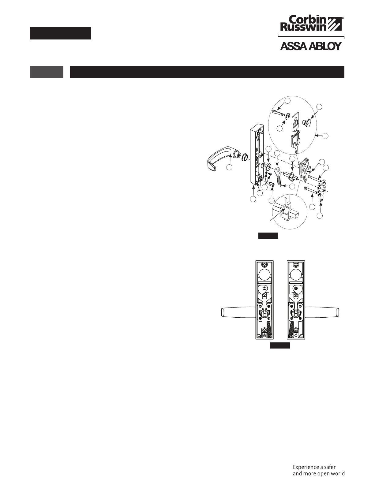
4 Changing Hand of Trim
Loosen screw (1) and remove interlocking assembly (2). (Figure15A)
Always wear eye protection while working.
1. Unscrew the lower thru-bolt stud (11) with a
3/8" wrench.
2. Remove mounting plate (6) and mounting
posts.
3. Switch mounting posts (7) so they occupy the
opposite positions on the mounting plate (6).
4. Note the original position of the extension
spring (16) and lower plate (9) in the
escutcheon (14). Unhook the extension
spring from pin (13).
5. Remove spring (16), lower plate (9) and
locking hub (8) assembly together.
6. Detach extension spring (16) from lower plate
(9) and locking hub assembly (8).
7. Flip lower plate on locking hub assembly
spindle so that the spring hole is on the
opposite side.
8. Reattach hook end of spring to lower plate.
9. Unscrew cap screw w/spacer (12) using a
5/32" Allen wrench.
10. Move to opposite hole and tighten firmly.
11. Rotate lever to position shown in Figure16 for
desired hand.
12. Tighten retaining nut (10) firmly by hand and
then back off one notch until pattern appears.
13. Attach bottom of spring (16) (closed loop) to
pin (13). Hold lever horizontal while inserting
locking hub assembly (8) and lower plate (9)
into retaining nut (10) escutcheon with lower
thru-bolt stud (11).
14. Refer to Figure16: Position hub (4) for
required function and hand, and ensure
that spindle (5) is vertical. Note position of
interlocking assembly hook when positioning
hub.
Figure B
Figure15
Figure A
Interlocking
Assembly
Bottom
Hook
5
4
3
2
1
7
6
14 11
12 16
10
9
8
13
15
7
Functions
HubSpindle
Interlocking
Assembly Hook
24, 66 30
Figure16