TigoBridge SOM Integration Quick Guide
All information presented in this document is confidential and for internal use only.
Copyright 2019, CoreTigo Ltd. Page 2 of 11
Approval Table ................................................................................................................................. 3
Revision Control ............................................................................................................................... 3
Glossary/Abbreviations..................................................................................................................... 3
1 Overview ................................................................................................................................... 4
1.1 Objective ............................................................................................................................ 4
1.2 TigoBridge SOM Integration folder content ...................................................................... 4
2 Mechanical design .................................................................................................................... 5
2.1 TigoBridge SOM dimensions ............................................................................................ 5
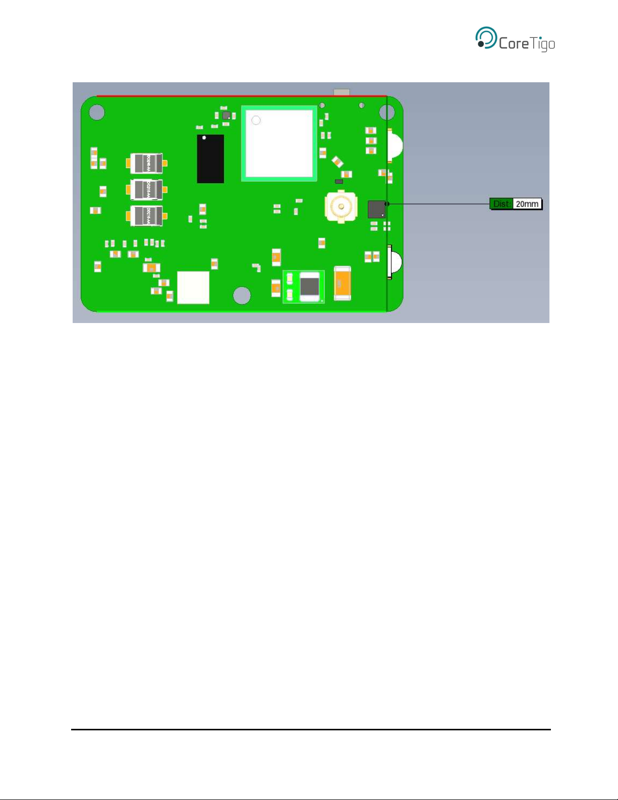
2.2 Antenna connection ............................................................................................................ 6
2.3 Placing the BTB connectors ............................................................................................... 7
3 Electrical design ........................................................................................................................ 8
3.1 BTB connectors schematics ............................................................................................... 8
3.1.1 Pinout description ....................................................................................................... 8
3.1.2 Application and implementation ................................................................................. 9
Figure 1: TigoBridge SOM height .................................................................................................... 5
Figure 2: TigoBridge SOM length .................................................................................................... 5
Figure 3: TigoBridge SOM width ..................................................................................................... 6
Figure 4: Matching board BTB connectors location......................................................................... 7
Figure 5: BTB connectors schematics .............................................................................................. 8
Figure 6: IOL Device M12 schematic .............................................................................................. 9
Figure 7: Pairing button schematic ................................................................................................. 10
Figure 8: RGB Led schematic......................................................................................................... 10
Figure 9: Power Led indication schematic ...................................................................................... 11
Table 1: BTB connector pinout......................................................................................................... 8
Table 2: Pairing button functionality .............................................................................................. 10
Table 3: RGB Led functionality ..................................................................................................... 10
Table 4: Power Led indication functionality .................................................................................. 11