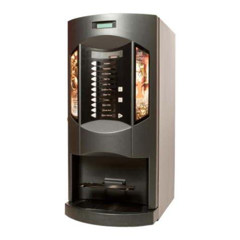
Cornelius LOOP STYLE XL CC User manual

LOOP STYLE XL CC

LOOP Style XL CC
Manual operation Countertop Vending Machine
LOOP Style XL CC
Page 2
Cornelius DeutschlandGmbH
Document no: TD1009600EN
Version A, 24.09.2019, Index 0
Manual operation English
Legal notice
Document no.: TD1009600EN
Countertop Vending Machine
Model
LOOP Style XL CC
Version A
Date of issue: 24.09.2019
Revision status: Index 0
Protection notices (in accordance with DIN ISO 16016:2002-5)
The reproduction, distribution and utilization of this document as well as the communication of its contents are
prohibited, unless expressly permitted. Violations shall result in an obligation to pay damages. All rights
reserved with regard to filing for/registering patents, utility models or design patents.
www.cornelius-emea.com
Phone: +49 (0) 21 73 / 79 3 –0
Fax: +49 (0) 21 73 / 77 4 –38
Email: info@cornelius.com
Cornelius Deutschland GmbH
Carl-Leverkus-Str. 15
40764 Langenfeld
Germany

LOOP Style XL CC
Manual operation Countertop Vending Machine
LOOP Style XL CC
Page 3
Cornelius DeutschlandGmbH
Document no: TD1009600EN
Version A, 24.09.2019, Index 0
Table of Contents
1Safety .............................................................................................................................................................. 4
1.1 Intended use.............................................................................................................................................4
1.2 Improper use.............................................................................................................................................4
1.3 Staff ..........................................................................................................................................................5
1.3.1 Operator ............................................................................................................................................5
1.3.2 User...................................................................................................................................................5
1.3.3 Expert................................................................................................................................................5
1.4 Presentation of warning............................................................................................................................5
1.5 Safety instructions ....................................................................................................................................5
1.5.1 General safety information................................................................................................................ 5
1.5.2 Disclaimer of liability and warranties.................................................................................................6
1.5.3 Safety information to prevent personal injury and equipment damage.............................................6
2Transport and packaging..............................................................................................................................7
2.1 Storage..................................................................................................................................................... 7
3Disposal..........................................................................................................................................................8
4Installation Requirements............................................................................................................................. 9
4.1 Installation Sites........................................................................................................................................9
4.2 Electrical Connections..............................................................................................................................9
4.3 Hydraulical connections............................................................................................................................9
5Installation....................................................................................................................................................10
5.1 Water Connection...................................................................................................................................10
5.2 CO2Connection......................................................................................................................................10
5.3 Connecting Syrup...................................................................................................................................10
6Putting into and out of Operation ..............................................................................................................11
6.1 Putting into Operation.............................................................................................................................11
6.2 Turning on the Unit.................................................................................................................................11
6.3 Purging the Syrup Systems....................................................................................................................12
6.4 Adjusting the Water-to-Syrup Ratio for Post-mix....................................................................................12
6.5 End of Operation (End of dispense-time)...............................................................................................12
6.6 Daily Inspection ......................................................................................................................................12
6.7 Taking out of operation (Vacation, end of season).................................................................................13
7Cleaning and Disinfection Directions........................................................................................................13
7.1 Cleaning Directions ................................................................................................................................13
7.2 Cleaning and Disinfection Procedure before use...................................................................................14
8Problems and Troubleshooting.................................................................................................................. 17
9Technical Data..............................................................................................................................................18
10 Flow Chart.................................................................................................................................................19
11 Circuit Diagram.........................................................................................................................................20
12 Exploded View / Sprengzeichnung.......................................................................................................21
13 Spare Part List / Ersatzteilliste.............................................................................................................. 22
14 Declaration of Conformity.......................................................................................................................23
LOOP Style XL CC
Manual operation Countertop Vending Machine
LOOP Style XL CC
Page 4
Cornelius DeutschlandGmbH
Document no: TD1009600EN
Version A, 24.09.2019, Index 0
1 Safety
1.1 Intended use
By using the unit as intended you will not only protect yourself, but also prevent damage occurring to the
unit and its components!
The intended use of over counter coolers from the LOOP STYLE series (referred to as “unit” in the
following) is to refrigerate and convey non-alcoholic beverages and their basic ingredients. CO2 or
electric pumps are used as conveying equipment for the brands.
The unit is only suitable for stationary installation in a closed room. Stationary installation is to be carried
out by an expert in compliance with all of the specifications given this manual.
The inlet temperature of the liquid must not exceed 32°C otherwise the pressure in the refrigeration cycle
will rise above specification.
Minimum ambient temperature 10°C, maximum ambient temperature 32°C
The intended use means that you will carry out all activities with and on the unit to the specifications
provided in this document.
This unit is only to be operated by those who meet the requirements set out in this document.
Work on the unit and its components not included in the activities described in this document may only be
performed by experts, means authorized and skilled people.
1.2 Improper use
Improper use of the unit and unauthorized modifications to the unit and its components may cause
personal injury and equipment damage for which Cornelius Deutschland GmbH shall assume no liability.
Improper use of the unit is prohibited.
The following in particular is regarded as improper use:
-Mobile operation of unit
-Operation of unit in areas without supervision by skilled personnel
-Operation of the unit in an area, where water jet is possible.
-Cleaning with a water jet
-Any handling as e.g. use or service by children under the age of 8 years
-Any cleaning or service by children without supervision by a skilled, authorized adult.
-Use by persons (including children) with physical, sensory or mental disabilities or those with
insufficient experience and knowledge, unless they are supervised by a person responsible for their
safety, or this person has instructed them in the use of the unit.
-Use by those under the influence of medication, alcohol, drugs or other substances which impair their
physical, sensory or mental abilities.
-The refrigeration of non-specified liquids and those above the maximum supply temperatures as this
may cause unacceptably high pressures to build up in the refrigeration circuit.
-Operating the unit below the minimum and above the maximum ambient temperatures (minimum and
maximum temperatures see chapter 3.3, page 15).
-Operating the unit with conveying media other than those defined in this document.
-Operating the unit in locations and ambient conditions which do not fully meet the requirements of this
manual
-Operation of the unit by untrained staff

LOOP Style XL CC
Manual operation Countertop Vending Machine
LOOP Style XL CC
Page 5
Cornelius DeutschlandGmbH
Document no: TD1009600EN
Version A, 24.09.2019, Index 0
1.3 Staff
Operator
The operator is the natural or legal person who uses the unit or on whose behalf the unit is used. The
operator must ensure that the unit is only used as intended, in observance of the safety instructions set
out in this document.
The operator must ensure that all users read and understand the safety information. The operator is
responsible for the planning and proper implementation of regular safety inspections and maintenance
work.
With regard to operating the unit, Cornelius Deutschland GmbH recommends observing the national
regulations of the country of use which govern the operation of drink-dispensing systems.
User
The operator specifies who will operate this unit. Cornelius recommends the following:
-If this unit is only to be operated by employees, they are to be instructed in its use, demonstrate
their abilities to use it to the operator or their authorized representative, and be expressly charged
with its use. This document is to be available to staff at all times.
-If this unit is openly accessible and set up so that untrained staff can use it, the operator is to
provide instructions for use directly at the unit; these must be clearly understood by this group of
people, therefore ensuring that the unit will be handled safely.
Expert
An expert in terms of this document refers to someone who has the relevant training, experience and
information and knowledge of relevant standards, laws, regulations, accident prevention regulations,
generally accepted safety-related regulations and operating conditions to be able to perform the required
activities as well as recognize potential risks and avert them.
For assignments requiring expert knowledge, e.g. in electrical engineering, mechanics or fluid technology,
only skilled workers with the right qualifications are to carry these out.
An expert must also have received technical training in the unit-specific special features of Cornelius
products. The assigned tasks are always to be carried out in compliance with this manual.
1.4 Presentation of warning
The documents supplied with the unit provide warnings regarding any hazards that might exist.
1.5 Safety instructions
General safety information
Any work on the unit and its components which goes beyond the operation and servicing and
maintenance that the operator is authorised for, may only be performed by experts (for a definition of
experts, see chapter 1.3.3, page 5). Furthermore, it is crucial that when performing work on the unit
all safety information is observed; this information is set out in the following sections. Some of the
tasks may have additional safety information which highlights the specific hazards associated with
such work.

LOOP Style XL CC
Manual operation Countertop Vending Machine
LOOP Style XL CC
Page 6
Cornelius DeutschlandGmbH
Document no: TD1009600EN
Version A, 24.09.2019, Index 0
Disclaimer of liability and warranties
If work is undertaken on the unit which is not described in this document, Cornelius Deutschland GmbH
shall not assume any liability for any resulting hazards and damages. The same applies to described
work which is partly or not fully performed in compliance with the regulations set out in this document.
Warning! Risk of personal injury and equipment damage due to improperly executed work
Improperly executed work at the unit will cause dangers to persons and damage to the
unit.
Have all work at the unit carried out by Cornelius Deutschland GmbH or by a
service partner.
Warning! Risk of personal injury and equipment damage due to the use of non- approved spare parts
and accessories
Using spare parts and accessories that are not recommended by the manufacturer may
lead to personal injury and equipment damage.
For your own safety and to protect your warranty, only use original spare parts.
Safety information to prevent personal injury and equipment damage
Please always observe the following safety information in order to prevent personal injury occurring:
Danger! Risk of death from electric shock
Touching live electrical parts will result in a risk of electric shock!
Do not carry out any work on the electrical system.
Warning! Risk of burns when touching hot parts of the unit
Touching parts of the unit after it has been in continuous use over an extended period of
time will result in a risk of burns.
•Take appropriate safeguard measures, such as by
wearing heat- resistant protective gloves.
Danger!Risk of poisoning and risk of explosion due to improper handling of CO2 cylinders
Risk of death from CO2!
Observe all information on occupational safety for the safe operation of dispensing
systems as applicable in the respective country of installation.
Danger!Risk of personal injury and equipment damage due to improper operation
Risk of death from improper operation!
Make sure that only users who are users as defined in the user section use the
unit; see chapter 1.3.2, page 5.
Children must be supervised to ensure that they do not play ator with the unit.

LOOP Style XL CC
Manual operation Countertop Vending Machine
LOOP Style XL CC
Page 7
Cornelius DeutschlandGmbH
Document no: TD1009600EN
Version A, 24.09.2019, Index 0
Danger!Risk of personal injury and equipment damage due to leaking refrigerant
In accordance with DIN EN 378 standard, part 1, the refrigerant used with this unit, R290
(propane), is classified as safety group A3. It is not poisonous and not caustic or
corrosive. However, it is combustible and highly flammable. As a result, a potentially
explosive atmosphere may occur in the case of leaks.
The refrigerant is heavier than air and, consequently, accumulates at the bottom and may
enter lower lying areas (e.g. sewage systems). At high concentrations, this may lead to a lack
of oxygen, resulting in a risk of suffocation. Lower concentrations may have a narcotic effect.
The refrigerant has a very slight, somewhat sweet smell.
Avoid any damage to components that carry the refrigerant
If you suspect any leaks, however small, shut down the unit, air the room well and
inform your service partner.
Do not allow direct contact with the skin of any leakingrefrigerant.
Fire, open flames and smoking are prohibited.
If you begin to notice any smell, leave the room and alert the fire service
Notice! In particular, safety standards are to be observed in their scope of validity
(e.g. EN 60335-2-75).
2 Transport and packaging
Choose a suitable packaging when returning the unit itself or one of its components to Cornelius Deutschland
GmbH, e.g. for repairs. In particular, make sure that the unit and any components are protected from
shock/impact, moisture, dirt and electrostatic discharge (ESD). This will prevent transport damage to the unit
and to the components, for which the manufacturer shall assume no liability.
Caution!
Component damage due to freezing liquids
Ambient temperatures that are below freezing will lead to the freezing of any water or cleaning
agent residue remaining inside the unit. This will lead
to damages of internal components.
-Before shipment, storage or relocation of the unit, the unit is to be cleaned and the cleaning
solution is to be fully drained from the unit.
2.1 Storage
Avoid excessive temperature fluctuations as condensate may form, which in turn may cause damage to the unit
or to the components.
The permissible storage temperature is -10 °C to +50 °C.
The acclimatization period is 6 hours.

LOOP Style XL CC
Manual operation Countertop Vending Machine
LOOP Style XL CC
Page 8
Cornelius DeutschlandGmbH
Document no: TD1009600EN
Version A, 24.09.2019, Index 0
Caution!
Damage due to improper storage
Dirt or moisture entering a unit, as well as certain weather conditions (e.g. condensate forming
at the unit, sunlight) will cause damage to the unit and its components.
• Protect the unit and its components by storing the unit in a clean and dry place, and by
ensuring stable ambient conditions.
• If possible, store the unit in its original packaging. Unpacked units must be covered with a
dustproof cover. No condensate must form under the cover.
Caution!
Risk of electrostatic charge!
Improper handling or storage may result in electrostatic charges.
-If possible, store units and/or any electronic components in their original packaging.
-Keep units and/or electronic components away from charged objects, fields and insulators.
-Avoid electrostatic charges when removing packaging and/or handling electronic
assemblies and components by working at an ESD protected workstation or work area.
-When working at the unit or its components wear a grounding (antistatic) wrist strap at the
very least and wear antistatic gloves if necessary.
Caution!
Component damage due to material ageing
Material can age due to long storage periods, thereby affecting the material’s properties (e.g.
plastics and seals may become brittle). The properties of lubricants may change due to long
storage periods.
-Check the assemblies and components for damage before each use/before installing
them. Do not install assemblies or components that show visible signs of ageing.
Caution!
Component damage due to freezing liquids
Ambient temperatures that are below freezing will lead to the freezing of any water or cleaning
agent residue remaining inside the unit. This will lead to damage to internal components.
Before shipment, storage or relocation of the unit, the unit is to be cleaned and the cleaning
solution is to be fully drained from the unit.
3 Disposal
Disposal of the units must be carried out in compliance with the applicable local and/or national and
international regulations. Units must not be disposed of with household waste.
If the unit contains fuels or lubricants in liquid, paste-like or gaseous form, such as oil, grease, cooling
agents etc., such fuels or lubricants are to be collected using appropriate measures and disposed of in
compliance with the applicable local and/or national and international regulations. Such fuels or lubricants
must always be prevented from seeping into the ground, the sewage system and any bodies of water, and
must always be prevented from entering the atmosphere.

LOOP Style XL CC
Manual operation Countertop Vending Machine
LOOP Style XL CC
Page 9
Cornelius DeutschlandGmbH
Document no: TD1009600EN
Version A, 24.09.2019, Index 0
4 Installation Requirements
4.1 Installation Sites
Comply with the valid national regulations for installation sites and electrical connections. Ventilation of the
installation sites must be appropriate for unit output. Inadequate ventilation of the unit will result in
overheating and damage. Always make certain that no intake or discharge vents are covered or blocked.
LOOP Style XL
Heat output in watt 945
Air flow in m3/hour 400
4.2 Electrical Connections
A socket outlet with an earthed contact featuring a maximum protection of 16 amperes is required.
The line voltage must always be within the following tolerances: 230 VAC +6%/-10% / 50 Hz
LOOP Style XL
Power consumption in watt 790
Should placement of the unit require an extension cable, please note the following points:
Cable length must not exceed 50 meters.
Only use cable with a size of 2.5 mm2.
Only one unit is allowed per extension cable.
4.3 Hydraulical connections
The hydraulical connections have to comply to all national mandatory norms, laws and directives. They
must be carried out only by skilled and authorized personnel with appropriate tools.

LOOP Style XL CC
Manual operation Countertop Vending Machine
LOOP Style XL CC
Page 10
Cornelius DeutschlandGmbH
Document no: TD1009600EN
Version A, 24.09.2019, Index 0
5 Installation
The unit must be installed by a trained service technician.
Please take care, that the socket for the unit is always accessible.
If the power supply cable to the unit is damaged, it has to be replaced by the manufacturer, the service
partner or any other qualified person to avoid safety hazard.
The unit must be planar aligned. Max. angle of +/-2 °C is permitted.
5.1 Water Connection
The connections to mains water are not delivered with this unit. Please use only water connections that are
in line with IEC/EN 61770. Connect the unit to a feed line with an inner diameter of 8 mm. We recommend
use of a water filter and a water pressure regulator for the water input. To permit flushing of the filter, a t-
piece should be mounted downstream of the filter. The water flow pressure should be 0,2 MPa (2 bar)
(mount control pressure gauge on water pressure regulator). The unit must only be operated with a water
pressure regulator.
5.2 CO2Connection
You will require a two-stage pressure regulator, 0,7 MPa (7 bar).
Use tubing with 4mm ID.
One pressure is for the carbonator bowl and the other one for the syrup flow.
Set the CO2-pressure: see table on page 21 (chapter 6.1).
5.3 Connecting Syrup
Use minimum 6 mm ID syrup tube to connect syrup container with correct cooling coil into the unit.

LOOP Style XL CC
Manual operation Countertop Vending Machine
LOOP Style XL CC
Page 11
Cornelius DeutschlandGmbH
Document no: TD1009600EN
Version A, 24.09.2019, Index 0
6 Putting into and out of Operation
6.1 Putting into Operation
Before starting operation of the unit the transport lock must be removed.
In order to ensure the proper function of the unit, please follow the below outlined points in their order.
Comply with the cleaning regulations defined by local laws before beginning each operation.
Connectors must be cleaned every time prior to attaching a beverage container.
Connect coupling to beverage container.
For soft drink note: gray coupling = CO2, black coupling =beverage/syrup
Open the valve of the CO2-cylinder and the pressure regulator. Check the CO2-pressure on the pressure
regulator.
It should be within the following standard values:
Syrup: 0,42-0,49 MPa (4,2-4,9 bar)
Carbonator pressure: 0,52-0,58 MPa (5,2-5,8 bar) cold carbonation
Diet/light-beverage: 0,21-0,28 MPa (2,1-2,8 bar)
Set the CO2-pressure by turning the control screw:
To increase the pressure: Clockwise
To reduce the pressure: Counterclockwise
Afterwards check the CO2-lines for leaks by closing the CO2-valve. The pressure (high pressure gauge)
displayed at the pressure regulator should not drop. If it does, notify the service technician immediately! Do
not forget to re-open the CO2-valve if no leakage is evident.
Open the water feed line and check the flow pressure. Standard value: 0,17-0,35 MPa (1,7-3,5 bar).
Set flow pressure at the control screw on the water pressure regulator:
To increase the pressure: Clockwise
To reduce the pressure: Counterclockwise
Check the beverage/syrup lines for leaks. Only a visual inspection is possible. If liquid is leaking, call a
service technician.
Close the water feed line. The pressure display should not drop. If it does, notify the service technician
immediately! Check the incoming waterline for leaks. Do not forget to re-open the water feed line if no
leakage is evident.
6.2 Turning on the Unit
The water bath must be filled to the overflow with tap water. Refer to the technical data for the amount
required.
Take care, that no water runs into the agitator motor. Reference: Use for this a suitable funnel and filler
tube.
To prevent algae from forming in the water, add the disinfectant Molco (PN 14-9670-150). The 150 ml
container of disinfectant is sufficient for 30 liters of water.
Insert the mains plug for the cooler into the socket outlet with an earthed contact.
Units with water bath are ice bank controlled. These units start working automatically after the water bath is
filled with water. The compressor will cycle off after the ice bank has been built. (full ice bank capacity). The
control board of the unit has a time delay for switching on and off the cooling system when it runs in ice

LOOP Style XL CC
Manual operation Countertop Vending Machine
LOOP Style XL CC
Page 12
Cornelius DeutschlandGmbH
Document no: TD1009600EN
Version A, 24.09.2019, Index 0
bank mode. After the cooling system is switched on the running time is no less than 5 minutes. Switch off
signals will be ignored in this time. After the cooling system switches off, the delay is no less than 3
minutes. Switch on signals will be ignored in this time. The 3 minutes delay occurs when turning on the unit
and after a break in power supply. This unit contains a 3-pin ice bank probe.
Post-mix units include a carbonator pump which switches on automatically and fills the carbonator bowl.
The carbonator pump switches off when the water has reached its highest level in the carbonator bowl but
after no more than 5 minutes. Long run periods are signs of leaks or insufficient water. It is then only
possible to turn the pump back on by executing a network reset (pulling out the mains plug briefly).
The carbonators in post-mix units are protected against running dry. If the flow rate quantity is so large that
the ”empty electrode” is activated, then the carbonator bowl is empty. In such cases voltage supply for the
post-mix valves will be switched off. A beverage withdrawal is only again possible if the carbonator bowl is
filled.
Release air from the carbonator bowl by pulling the safety valve for about 2 to 4 seconds.
6.3 Purging the Syrup Systems
Purging the syrup systems
Place a cup under the nozzle.
Manually open each syrup valve in turn and observe syrup flow. Purging is completed when all air is
removed from the system. If syrup continues to show air bubbles, check tightness of line connections.
6.4 Adjusting the Water-to-Syrup Ratio for Post-mix
Adjust the water flow rate on the post-mix valve in accordance with the valve supplier specifications.
Note: Allow the refrigeration unit to operate until minimal amount of ice has formed on the evaporation
coils, making this adjustment. Alternatively, allow the full ice bank to form (compressor cycle off) before
adjusting the ratio. The drink temperature should not be higher than 5°C.
The water-to-syrup ratio is measured by use of a ratio cup having two champers into which the soda and
the selected syrup are dispensed. The ratio, if incorrect, is adjusted by turning the related syrup flow
regulator adjusting screw located near the solenoid valve.
To increase the syrup flow rate: Clockwise
To reduce the syrup flow rate: Counterclockwise
6.5 End of Operation (End of dispense-time)
It is imperative that the CO2-cylinder and water line be turned off each time operation is ended.
Be sure to open again before continuing at operation.
6.6 Daily Inspection
Check whether carbon dioxide and water lines are open.
Check the beverage/syrup lines for leaks. Only a visual inspection is possible. If liquid escapes, call a
service technician.
Check the CO2-lines for leaks by closing valve on the CO2-cylinder. The inlet pressure indicated on the
pressure regulator should not drop. If it does, call a service technician immediately.
Do not forget to re-open the CO2-cylinder valve afterwards.

LOOP Style XL CC
Manual operation Countertop Vending Machine
LOOP Style XL CC
Page 13
Cornelius DeutschlandGmbH
Document no: TD1009600EN
Version A, 24.09.2019, Index 0
6.7 Taking out of operation (Vacation, end of season)
Perform the following steps in case of protracted standstill periods:
Close the CO2-cylinder, the CO2-stopcocks on pressure regulators and the water feed line.
Pull the mains plug out of socket outlet with earthed contact.
Detach the couplings from beverage containers.
Have the system emptied and cleaned.
Only trained specialists are to carry out this procedure.
7 Cleaning and Disinfection Directions
7.1 Cleaning Directions
Comply with the valid national regulations for cleaning bar equipment at the particular installation site.
Clean connection parts and tap fittings in advance whenever making connections or changing the type of
beverage. Clean parts coming into contact with air and beverage (e.g. dispense nozzle) on a daily basis.
The condenser fins must be cleaned in regular intervals. These vary according to the amount of dirt in the
air at the installation site (approximately every three months). This is best done with a brush and a vacuum
cleaner.
The water level in the water bath must be checked regularly and the contents must be exchanged at least
once annually. Algae formation can be reduced by adding disinfectant (order number 14-9670-150). For a
30 liters water-bath one disinfectant container is sufficient.
The unit is to be emptied and cleaned by trained person only based on the following recommendations:
To be cleaned by trained
specialists
CO2-
lines
Product-
lines
Syrup-
lines
Soda water-
lines
Before commissioning
X
X
X
Before each change
of type of beverage
X
X
Before and after a
pause
of more than 1 week
X
X
Every 2 weeks
X
Every 3 months
X
X
Every 12 months
X

LOOP Style XL CC
Manual operation Countertop Vending Machine
LOOP Style XL CC
Page 14
Cornelius DeutschlandGmbH
Document no: TD1009600EN
Version A, 24.09.2019, Index 0
7.2 Cleaning and Disinfection Procedure before use
In order to achieve a proper hygienic performance of the dispense equipment, it is crucial to run the initial
and recurring sanitization procedure (intervals according to DIN 6650-6) on all product and water lines of
the system.
Attention! Cleaning / sanitizing agents are harmful and may cause severe health injuries! During the
work with any agents make sure to always wear proper clothing (gloves, safety goggles,
etc.). Special attention must be taken during the flushing of the agent at the dispense
valves. It must be made sure, that no operator uses the dispense equipment during
sanitation (e.g. use clear signs on the valves, etc.)!
Take care of an adequate behaviour towards hygiene while working on the equipment
(e.g. disinfecting hands prior to work, etc.) in order to professionally deal with the matter.
The unit should be cleaned / sanitized starting as close as possible from the mains water
connection (wall outlet) to make sure that also the tubing is being treated.
Remark -> Water filters:
In case the system is equipped with a water filter, the filter cartridge needs to be removed before doing the
cleaning / sanitization and replaced by a blind plug that allows bypassing the filter. Do not use any empty
service filter cartridges to flush the sanitizing agent into the system, as this will not allow a proper and consistent
level of sanitizing agent in the unit.
In addition, the high levels of agent passing through the dispenser when using such cartridges may damage
components such as sealings, O-rings, etc. in the dispenser.
Remark -> Carbonator- / Circulation pumps
With units such as Triton, Apexx and Energize the carbonator- and soda circulation pumps must be turned off
during the cleaning / sanitization process (otherwise foaming issues will occur).
Remark -> Stillwater lines inside the cooler
In case your equipment has still water lines, it must be made sure that these are also being cleaned / sanitized.
In case your equipment currently does not use Stillwater, the line must be equipped with a stopcock to manually
drain sanitizing agent from this tube.
In case the Stillwater line is in general not being used on the cooler, it is recommended to disconnect this line as
close as possible from the water cycle and close the water line with a blind plug (this avoids areas within the
circuit which might not be sufficiently flushed).
Remark -> Electrical post-mix valves, which cannot be manually operated
These type of taps must be operated electrically. When doing this, it needs to be considered that on some
dispense equipment the 24V electrical power supply to the valves is cut, when the empty electrode in the
carbonator bowl is reached. In that case the empty sensing must be bypassed, by e.g. short circuiting all
connectors on the plug of the level probe connection.
Remark -> CO2- or Water pressure sensors on the dispense equipment
Depending on the type of equipment you may have CO2- or water pressure sensors installed, which will in case
of low CO2or low water supply cut the 24V power supply to the valves.
In order to still be able to operate the system during the sanitization process, it is required to short circuit such
sensors (make sure to put them back into operation after service).
Remark -> Post-mix valve blocks
It is recommended to clean / sanitize the valve blocks separately. Especially valve blocks with an integrated
stop cock (e.g. Lancer block) need special care, as the gap in the stop cock allows bacteria to collect, which
might not be sufficiently treated with the sanitizing agent.
In case the dispenser is out of operation (without cooling) for more than 10 days, it is necessary to run the
cleaning- and sanitization procedure prior to putting the unit back into operation.
Should it be necessary, to open a once sanitized system again (e.g. to install a new water filter)
all opened connections must be disinfected with a sanitization spray prior to reconnecting.

LOOP Style XL CC
Manual operation Countertop Vending Machine
LOOP Style XL CC
Page 15
Cornelius DeutschlandGmbH
Document no: TD1009600EN
Version A, 24.09.2019, Index 0
A.) Flushing-in of sanitization agent (e.g. P3 Ansep CIP from Ecolab)
1.) Syrup Lines
1.1) The product lines filled with syrup must first be flushed with water. For this an external
water distributor can be used to connect and flush several syrup lines simultaneously.
The post-mix valves should be operated on the syrup side only for flushing.
Attention! Gas driven syrup pumps must not see any positive pressures on the
incoming side of the pump, as this may damage the pumps.
1.2) Connect the water distributor to the CO2supply in order to drive the water out of the
syrup lines. This avoids that the sanitizing agent is being diluted in the tubing.
Afterwards close the CO2 gas and depressurize the complete system again.
1.3) Fill your cleaning tank with the cleaning / sanitizing agent according to the mixing ratios
given by the manufacturer of the agent.
(e.g. when using P3 from ECOLAB -> 50ml for 1 litre water = 5% solution)
In order to achieve a proper mixing in the cleaning tank, it is recommended to first fill
in the agent and then top-of with clean water.
1.4) Connect the syrup lines to the cleaning tank and dispense cleaning / sanitization agent
from every single dispense valve. Make sure that agent leaves from all installed taps.
2.) Water Lines
2.1) Close the water- + the CO2supply to the unit and depressurize the system with the taps
2.2) Disconnect the water supply to the unit and cut the power supply to the carbonator
pump in order to avoid dry running of the pump (e.g. by pulling the plug of the pump).
2.3) Connect the water line feeding the dispenser to CO2 gas pressure and drain all water from the tubing of
the system. This ensures that the sanitizing agent that is afterwards flushed into the dispenser is not
being diluted e.g. in the carbonator bowl.
Afterwards close the gas supply again and depressurize the system.
2.4) Connect the cleaning tank to the water inlet of the dispenser and pressurize the tank
with approx. 3 bars pressure (Attention! Remove any water filters before doing this!).
2.5) Pull the safety relieve valve on the carbonator bowl and carefully let some sanitizing agent leave the
valve. This ensures that the carbonator bowl is flooded completely with the sanitizing agent all the way
to the top.
Attention! : Avoid that excessive amounts (= >50ml) of agent is being introduced into
the water bath, as this will carry the risk of corrosion of metal parts in the water bath.
In case larger amounts were spilled, the water in the water bath needs to be replaced.
The LOOP post-mix cooler works with a membrane / diaphragm pump
please make sure the pump is in operation when the sanitizing agent
is being flushed into the unit. This will ensure that all parts of the pump will come into
contact with the sanitizing agent.
2.6) Flood the complete dispense system with the cleaning / sanitizing agent by operating
the post-mix valves. Ensure that on all valves clearly visible agent is being drawn.
Effect- / working time for the cleaning / sanitizing agent is min. 20 minutes!
In the meantime remove the dispense nozzles from the valves and sanitize them
manually by putting them for 20 minutes into sanitizing agent.
In case it is seen that the nozzles are heavily dirty, clean the nozzles mechanically
by using a clean brush and sanitization agent.

LOOP Style XL CC
Manual operation Countertop Vending Machine
LOOP Style XL CC
Page 16
Cornelius DeutschlandGmbH
Document no: TD1009600EN
Version A, 24.09.2019, Index 0
B.) Flushing-out of sanitization agent
1.) Syrup Lines
1.1) Disconnect the cleaning tank and bring out any remaining sanitizing agent from the syrup lines by
using CO2gas. Afterwards close the CO2supply and depressurize the system via the dispense valves.
1.2) Connect the water distributor and sufficiently flush clean water through the syrup lines (for this please
open only the syrup side of the dispense valves). In case a hygiene water filter is being used with the
dispenser, it is recommended to use for this flushing the water coming from the hygiene filter.
Attention! It must be ensured, that no cleaning / sanitizing agent remains in the dispense system
after service (risk of health injuries)!
The proof that all agent residues have been removed has to be tested with indicator
or test papers (contact agent manufacturer). The results have to be documented.
1.3) Connect the syrup containers again to the syrup lines and dispense syrup on the post-mix valves until
a consistent flow of syrup occurs again.
2.) Water lines
2.1) Pressurize the water line to the cooler with CO2pressure and dispense all sanitizing agent from the
valves. This makes it easier to flush out any remaining agent from the system.
2.2) Close the gas again and depressurize the unit via the dispense valves.
2.3) Install a new water filter cartridge and reconnect the unit via the filter to the mains water line again
(refer to filter manufacturer guidelines in case the filter needs priming prior to use).
In case a hygiene filter is being used on the dispenser, it must be ensured that the new
filter cartridge is inserted prior to flushing the system with water. This ensures that a
just sanitized system is not being contaminated again by using poor quality mains water
to flush out any remaining sanitizing agent.
Spray the filter head and the connecting position of the filter cartridge with an adequate
sanitizing spray to avoid any introduction of bacteria again.
2.4) Open the mains water supply. Pull the safety relieve valve on the carbonator bowl until
only clean water leaves the valve, to ensure that there are no residues of sanitizing
agent left in the head area of the carbonator bowl.
2.5) Open the CO2 gas supply to the carbonator and reconnect the carbonator pump to the
power supply.
2.6) Dispense sufficiently water from the post-mix valves to ensure that no sanitizing agent is
left in the system.
Depending on the unit type (Over counter dispenser / large soda circuit installation with
long python runs, etc.) the amount of water that needs to be dispensed may vary.
Attention! It must be ensured, that no cleaning / sanitizing agent remains in the
dispense system after service (risk of health injuries)!
The proof that all agent residues have been removed has to be tested with indicator
or test papers (contact agent manufacturer). The results have to be documented.
Dispense from each tap a few beverages to fully put the system back into operation again. The
cleaning / sanitization procedure must be documented accordingly and the
documentation must remain at the cooler (this may vary depending on local regulations).

LOOP Style XL CC
Manual operation Countertop Vending Machine
LOOP Style XL CC
Page 17
Cornelius DeutschlandGmbH
Document no: TD1009600EN
Version A, 24.09.2019, Index 0
8 Problems and Troubleshooting
Before seriously troubleshooting the dispense equipment, first check:
-Is the electricity to the unit interrupted?
-Are the beverage containers empty?
-Is the CO2-cylinder empty?
-Are all valves on CO2-cylinder open?
Type of problem Cause Remedy
Beverage too warm Condenser dirty Use brush to clean
while compressor or covered condenser between louvers
is running
Too much beverage Examine drink-draw capacity
being removed
Beverage too warm, Not enough water Fill up water level
Compressor not running in water-bath
Electronic control or Call service technician
compressor defective
Beverage foams at a tap Product/syrup Connect container
stored too long and with fresh basic material
enriched with CO2
Beverage foams at all taps CO2-pressure too high Set pressure
All products/syrup Connect container
enriched with CO2with fresh basic materials
All beverage too warm Check storage temperature
see ”Beverage too warm”
Valve only pours syrup Fault in Check if water feed line is
water circulation open
Check water flow pressure
of 0,2 MPa (2 bar)
Check if the carbonator
motor is running,
If not call service technician
Valve defective Exchange valve
Water lines frozen Call service technician
CO2-volume in the Air in carbonator Bleed air
beverage to low (only post-mix)
(flat drinks)
CO2-pressure too low Adjust pressure
Too much or not enough Regulator in tap Call service technician
Syrup in beverage is clamping
Delivery pressure for Adjust CO2-pressure
Syrup too low or too high

LOOP Style XL CC
Manual operation Countertop Vending Machine
LOOP Style XL CC
Page 18
Cornelius DeutschlandGmbH
Document no: TD1009600EN
Version A, 24.09.2019, Index 0
9 Technical Data
Output capacity soft drink 0,2/0,3 liters
Peak dispense at 2 drinks per minute 322 (0,3 l)
Continuously –drinks per hour 75 (0,3 l)
Supply voltage 230V/50Hz
Power consumption in Watt 790
Compressor output in Watt (HP)* 447 (1/3)
Cooling performance
in Watt 400
in kcal/h 344
Weight of ice bank in kg 11
Ice bank capacity in kcal 880
Ice build up in minutes 154
Water bath capacity in liter 29
Dimensions in mm
Height (soft drink) 655
Width incl. drip tray 435
Depth incl. drip tray 730
Shipping weight in kg 60
* at -10°C evaporation temperature
Cooling capacities and output capacity for soft drinks at 24°C ambient temperature and water or syrup
inlet temperature of 24°C and beverage outlet temperature of less than 5°C.
We reserve the right to make modifications.

LOOP Style XL CC
Manual operation Countertop Vending Machine
LOOP Style XL CC
Page 19
Cornelius DeutschlandGmbH
Document no: TD1009600EN
Version A, 24.09.2019, Index 0
10 Flow Chart
LOOP STYLE XL 5 Valve
0,2 –0,24 MPa (2-2,4 bar)
0,35-0,45 MPa ( 3,5-4,5 bar )
0,35-0,4 MPa ( 3,5-4,0 bar)
0,05-0,1 MPa K( 0,5-1 bar )
LOOP STYLE XL 6 Valve
0,35-0,45 MPa ( 3,5-4,5 bar )
0,35-0,4 MPa (3,5-4,0 bar )
0,05-0,1 MPa (0,5-1 bar )
0,2-0,24 MPa ( 2,0-2,4 bar )

LOOP Style XL CC
Manual operation Countertop Vending Machine
LOOP Style XL CC
Page 20
Cornelius DeutschlandGmbH
Document no: TD1009600EN
Version A, 24.09.2019, Index 0
11 Circuit Diagram
This manual suits for next models
5
Table of contents
Popular Vending Machine manuals by other brands

AMS
AMS SENSIT II Operation and service manual

N&W Global Vending
N&W Global Vending Krea Installation - use - maintenance

Seaga
Seaga JDL-2 COMBO Service and parts manual

Westomatic
Westomatic Signature Operator's & installation manual

Crane
Crane 721 parts manual

AMS
AMS SENSIT II Operation and service manual

SandenVendo
SandenVendo SVE JDE User and maintenance manual

Worldline
Worldline davinci III Vending Integration guide

Crane Merchandising Systems
Crane Merchandising Systems Genesis Technical manual

Fastcorp
Fastcorp DIVI Setup and user guide

Anvil
Anvil POPCORN MACHINE 8oz Installation, Operation and Care Manual

Crane Merchandising Systems
Crane Merchandising Systems Voce Media Series Service information