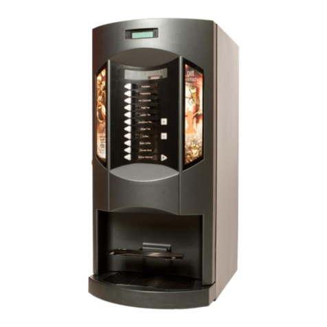
Azkoyen STEP 74 Manual

Technical Information
S T E P
AZKOYEN Industrial, S.A.
Avda. San Silvestre, s/n
31350 Peralta (Navarra) Spain
Tel.:+34948709709
www.sat.azkoyen.com

1ª 10155 ES 9 - 2009
2
I N D E X
1. INTRODUCTION
1.1. Copyright
1.2. Principle technical characteristics
1.3. Product range
2. DESCRIPTION OF COMPONENTS
1. Bill reader
2. Product labels + Selection button
3. Price display
4. LED column
5. Product collection tray
6. Front plate and refund button
7. RF Emitter - Receiver
8. Information screen
9. Coin collection tray
10. Glass
11. Product channels
12. Half channels
13. Coin validation system
14. Cash box
15. Power supply, Rack and PCBs
3. INSTALLATION AND STARTING UP
3.1. Installation and starting up
3.2. Check points
3.3. Faults and possible solutions
4. WORKING CONDITIONS AND NORMS
5. CLEANING AND MAINTENANCE
6. DIMENSIONS

1ª 10155 ES 9 - 2009
3
1. INTRODUCTION
The machines in the STEP series are designed for the automatic sale of packets of cigarettes and
other packeted products. They have been designed and provided with the latest technologies with
the objective of satisfying all the requirements of operators and users of this type of machine.
1.1 COPYRIGHT
The information contained in this manual is subject to modifications without previous
communication and do not represent any compromise on behalf of Azkoyen Industrial S.A.
This document contains information that is private property and all rights are reserved. No part of
this document may be copied, transmitted, recorded, or translated to another language without
the written consent of Azkoyen Industrial S.A. with the exception of conforming to the laws of the
country.
1.2 PRINCIPLE TECHNICAL CHARACTERISTICS
Selectionoftheproductusingakeyboardofthetypecalled“proximity”.
Illuminated product labels that are easy to change.
The product labels can be seen from an angle of 180º.
The Collection tray and the Coin exit illuminate at the moment the product or change is
delivered to the user of the machine.
Informationscreen:fluorescenttypegraphicalDisplay 96 x 8, with a row of 16
characters.
Up to 5 programmable publicity messages.
Flexible ABS plastic channels designed for fast, easy loading and easy removal (no
tools needed).
Independent channels and selections that can optionally be associated using the
programming of the machine.
Channels are adaptable to different formats of the packets.
Microprocessors with Flash technology.
Options of communication ports: RS232, Bluetooth, and Infrared.
Possible use with Telecommunication equipment, GPRS, UMTS and TCP/IP.


1ª 10155 ES 9 - 2009
4
Programme with statistical data of partial and accumulative sales.
Electronics in modules and connected in Rack.
Reliable coin and note discrimination and in the rejection of frauds.
14 fixing points on the door of the machine.
Very low electrical consumption. At rest, the power is around 21w in the smaller
model, the STEP-41 and 26w in the larger model, the STEP-87.
1.3 RANGE
Factory default setting of the different ranges of machines in the STEP series are shown in the
following table:
Ranges
Cabinet
Coin
system
Buttons
Full
Channels
Short
Channels
Half
Channels
Note
reader
Capacity
of
standard
packets
STEP 41
Double Change
giver 21 1 0 14 No 292
Double Hopper U 3 0 18 444
STEP 61
Triple Hopper U
32
13 0 10
No
700
Double Hopper U 3026 588
STEP 74
Triple Hopper U
40
17 0 14
No
932
Double Hopper U 3034 732
STEP 87
Triple Hopper U
48
21 0 18
No
1102
Different kits can optionally be installed depending on the model of machine: note reader,
Individual Display to indicate the price of sale of the different products, card or key readers of the
pre-pay type, publicity panel in the door, channel for the sale of lighters, etc.

1ª 10155 ES 9 - 2009
5
2. DESCRIPTION OF COMPONENTS
1. Note reader
In the position indicated, the note reader Kit is installed. It accepts 5, 10 and 20 €notes and the
communication protocol is MDB (Multi-Drop Bus).
The note reader that is recommended for the machines in the STEP series is the model Eureka
from Coges. This note reader is doted with a Stacker (note storage) with capacity of 300 notes.
For more information see the technical manual (accessory chapter) of the
Coges Eureka model note reader
1
2
3
4
5
6
8
7
10
9

1ª 10155 ES 9 - 2009
6
Installation of a Note reader
1. With a Phillips screwdriver, remove the
transport protection screws that are indicated
with the yellow arrows in the figure on the left
and tilt down the grid of channels in the door.
2. With a Phillips screwdriver, remove the
screws of the front panel.
3. The front panel is fixed with three tabs in
three slots in the door
4. Lift panel free of the three fixings.
5. Remove the glass backwards and lift it out of
its fixings.

1ª 10155 ES 9 - 2009
7
6. Fit the cable ties (ref. 09717030) that
corresponds to the door.
7. Place the MDB wiring loom
(ref.43210320) in the cable ties. Pass it
through the hole in the door.
8. Remove the black cable tie cover and route
the cables as indicated in the figure.
9. Continue routing the cable as shown by
passing and fixing the cable with the cable
ties as indicated in the figure.
10. Remove the black cable tie cover and route
the cables as indicated in the figure.

1ª 10155 ES 9 - 2009
8
11. Connect the communication cable to the
port on the control board, connector J7 and
the power supply to the I/O board connector
J12.
12. Replace the glass and the new front panel.
13. Remove the gauge walls, the plastic and
metal side wall.
14. Place the new walls, and the new gauge.
15. Remove the cover of the reader and with
the same screws fasten the reader as
shown. Connect the MDB wiring loom of the
reader to the wiring loom previously
installed.
16. Tilt the grid down again. Consult the
programming manual to programme the note
reader.

1ª 10155 ES 9 - 2009
9
2. Product labels + selection buttons.
The machine has an innovative system for the selection of the product; it is called Capacitative
Proximity Keyboard.
All the Product labels are illuminated for easy identification.
There are two types of Product keyboards, for the model STEP41, a keyboard of 7 selections is
used and for the rest of the models have one of 8 selections.
The machine recognises each one of the keyboards using “addresses” that are configured with
four dip-switches on the board of the keyboard.
SW1 SW2 SW3 SW4 Position Keyboard
ON OFF OFF OFF
First position
OFF ON OFF OFF Second position
OFF OFF ON OFF Third position
OFF OFF OFF ON Fourth position

1ª 10155 ES 9 - 2009
10
It has made a modification in the boards to improve the system to indicate the position of them
with a 2,54mm. molex connector It uses a jumper molex to indicate the position of the boards.
Reference. 03803490
To indicate the position of the buttons it
uses jumper molex.
1º Position
2º Position
3º Position
4º Position

1ª 10155 ES 9 - 2009
11
3. Price of sale of the product
As an option, the machine can be supplied with Price display boards for each one of the product
selections that show the user the price of sale. If the machine does not have this option, the price
of sale is shown on the Information Screen when the user presses on the Product label of the
product that they wish to buy. In both cases, with Display for each product selection or with prices
shown on the Information screen, the machine can be programmed to work with zero, one, two or
three decimals.
There are two types of price display boards, for keyboards of 8 selections and of 7.
Installation of the price display boards
With a Phillips screwdriver, remove the
transport protection screws that are indicated
with the yellow arrows in the figure on the left
and tilt down the grid of channels in the door.

1ª 10155 ES 9 - 2009
12
With a, loosen the two screws shown with the
red arrows. Lift and remove the keyboard
cover.
Disconnect the cables on the selection panel,
yellow arrows.
With a Phillips screwdriver, loosen the three
screws shown with the red arrows. Lift and tilt
down the keyboard bracket.
Dismantle the set of buttons on the panel,
freeing the 4 clips that hold it to the metal
panel.

1ª 10155 ES 9 - 2009
13
Fit the price display board pressing firmly on
the plastic support. Verify the correct position
of the fixing clips.
Re-connect the cables that join the price display
boards to the button boards.
Connect the power supply cables of one price
board to another. Yellow Arrows.
Replace the keyboard panel into the machine
fixing it with the three screws.
The power supply cable of the price display
board (red – black) is installed in series in the
machine.
Fit the Bracket cover fixing it with the two
screws

1ª 10155 ES 9 - 2009
14
4. Column of LED diodes
The front panel of the machine has a column
of LED diodes (green) that illuminate when the
user of the machine purchases a product. The
LED diodes illuminate at the same time as the
extraction of the product and its delivery to
the product collection tray.
5. Product collection tray
This is the area at the front of the machine where the product is delivered to the user. The
collection tray has a row of LED diodes (white) that illuminate when the user of the machine
collects the product and change. The objective is to facilitate the collection of the product and
change if it is required.
6. Coin entry front plate and reject button
The front plate is located on the upper part of the door of the machine. The users of the machine
insert the coins here. Next to the coin slot is the reject button that allows the user to cancel the
purchase and recuperate the coin/s that were inserted into the machine.

1ª 10155 ES 9 - 2009
15
7. RF Emitter - Receiver
It is used to control the access of minors to the machine.
The owner of the machine, at the petition of the user,
activates the machine with a remote control so the user
may purchase the cigarettes.
For the Receiver to recognise a new Emitter, the following hast to be carried out:
1. With the machine switched on, hold and press button 1 of the receiver and the LED diode will
flash.
2. Press button 2 on the Emitter. Now the receiver is registered to the frequency that comes
from the Emitter and it is shown by switching on the LED diode for two seconds.
3. The process finished when you release button 1 on the Receiver.

1ª 10155 ES 9 - 2009
16
The receiver can recognise a maximum of three emitters
The machine remains active for the purchase for 45 seconds. After this time
the machine is blocked until it receives a new order from the remote control
The maximum distance the remote control is operative is 30 metres without
obstacles
8. Information screen
9. Coin collection tray
The Coin collection tray on the machine delivers the coins when:
+ The cancelation of the purchase process that can be chosen by the user of the
machine; the coins that the user may have inserted into the machine will be placed in
the Coin collection tray.
+ The coins that the machine gives as change at the end of the vend process when the
user has inserted more money than the price of sale of the product purchased.
The Coin collection tray will illuminate for a few seconds at the end of a purchase or if the reject
button is pressed by the user.
This screen is through which the machine communicates to
the user. Different messages or data that may be of
interest to the user can be transmitted during or after the
vend process. This is a fluorescent type graphical Display
96x8, with a row of 16 characters.

1ª 10155 ES 9 - 2009
17
10. Glass
The machine has a hardened smoked glass panel, (Venus grey) with a thickness of 4 mm. It has
a luminous transparency of 10%.
Changing a glass
With a Phillips screwdriver, remove the
transportation screws that are indicated with the
yellow arrows in the figure to the right and tilt
down the grid of channels in the door.
With a Phillips screwdriver, remove the screws of the front panel.
The front panel is held with three tabs and three slots in the door

1ª 10155 ES 9 - 2009
18
Lift the front panel and take it out from its
three fixings
Pull the glass out and lift it free of its fixing
Only use holding screws of 3,9x6.5 mm, THIS IS IMPORTANT.

1ª 10155 ES 9 - 2009
19
11. Product channels
11.1 Packets of cigarettes
In the following table are the different formats of packets of cigarettes with their measurements.
Definition of the format of the packet
of cigarettes Thick Wide Long
Standard (King size) 20-2652-6079-89
Short 20-2652-6065-75
Extra long 20-2652-6095-104
Wide (25) 20-2660-7579-89
Thick (30-35) 26-3060-7579-89
Very thick (40-50) 30-3660-7579-89
International 16-17,595-10584-89
10 cigarettes 16-17,543-4579-89
Only the channels in the cabinet side of the machine will take the Extra Long
format of packets
The following table shows the capacities of the channels depending on the format of the packet of
11
12
13
14
15

1ª 10155 ES 9 - 2009
20
cigarettes and the type of Wall of the channel.
Format of the packet Number of packets
-capacity-
Standard 40
Short 40
Extra long 40
International 40
Wide (packet of 25 cigarettes) 40
Very thick (packet of 50 cigarettes) 25
Channel with normal Wall
Packet of 10 cigarettes 52
Standard 26
Short 26
Channel with half upper
Wall
Extra long 26
Standard 10
Short 10
Channel with lower half
Wall
Extra long 10
11.2 Walls of the channels
Made of ABS plastic, the walls are very flexible which facilitates the process of loading the
packets. There are different Walls:
+ The Standard type that are used when the length of the packet of cigarettes is not
above 89 mm.
+ The Long type that are used when the length of the packet of cigarettes is not above
89 mm.
+ The Upper half.
+ The Lower half.
The dismantling of the assembly of its different elements is fast and easy.
This manual suits for next models
4
Table of contents
Other Azkoyen Vending Machine manuals