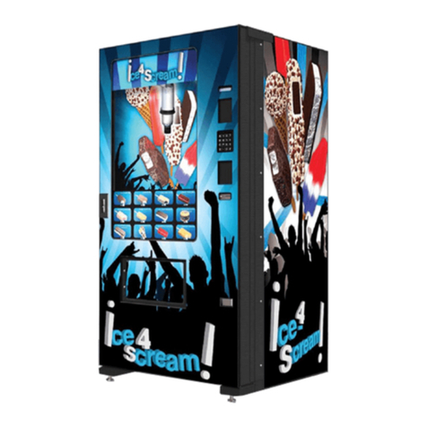
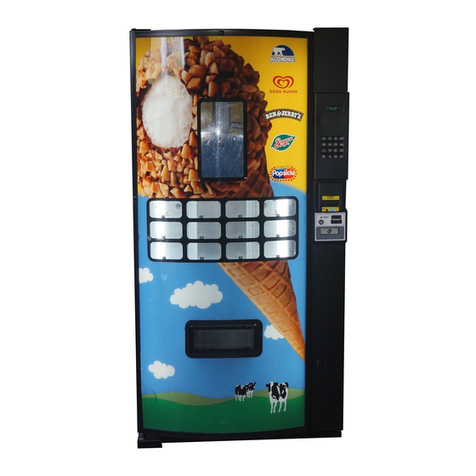
Fastcorp F820 Building instructions

F820 – Service and Parts Manual
Ver. FC031504

2
TABLE OF CONTENTS
I. SPECIFICATIONS / MAINTENANCE
A. General Specifications & Measurements B. Safety
C. Transport Considerations D. General Cleaning Considerations
E. Freezer Maintenance F. Removing The Control Console
G. Troubleshooting Tips H. Transformer Reset Checks
II. SETUP INSTRUCTIONS
A. Money Systems
1. MDB Coin Mechanism & Bill Acceptor Installation
B. Initial Power Up (Homing Sequence)
C. Bin Setup/ Product Loading
D. Preprogramming Configuration (DIP Switches)
1. Clearing the Memory
E. Programming (Overview of Menu Structure)
1 Getting started / Creating Selections 12 Set Service Phone #
2 Programming & editing after machine has
been operating
13 Sales PIN Code
3 Change Price 14 Vend Block
4 Sales Meters Total 15 VB PIN Code
5 Sales Meters Resetable 16 Health Timer
6 Edit Selection 17 Program Version
7 Create Selection 18 Display Language
8 Delete Selection 19 Line Mode
9 Selection #s 20 Machine Serial Number
10 Set Date 21 Group Sales Option
11 Set Time
22
23
Tokens & Coupons
Field Test
F. Free Vend / Test Vend
III. Troubleshooting
A. Glossary Of Useful Terms
B. Error Reporting Features
1 Non-Fatal
2. Fatal
C. Order Of Operation
1 Initiating The Vend Cycle 6 Picker Head Moves Up
2 Robot Carriage Moves Back 7 Robot Moves Left/Right
3 Robot Moves Right 8 Robot Carriage Moves Forward
4
5
Picker Head Moves Down
Vacuum turns on
9 Vend Cycle Complete
D. Troubleshooting Logic / Charts
1 L/R Stuck Motor 8 U/D Encoder Error
2 F/B Stuck Motor 9 Out Of Product
3
4
5
U/D Stuck Motor
Freezer Stuck Closed
Freezer Stuck Open
10
11
12
Vacuum Out Of Order
Bin Errors
False Vend
6 L/R Encoder Error 13 Product Sensor Error
7
1
2
3
4
5
F/B Encoder Error
E. Parts Replacement Instructions
Console
Computer Board
Front / Back Motor
Left / Right Motor
Up / Down Motor
14
6
7
8
9
Health Sensor Active
Freezer Door Motor
Picker Head Assembly
Health Sensor Assembly
Bubble Front Display
3
3
3
3
3
4
6
6
6
8
8
9
10
10
10
10
11
12
13
13
13
13
17
13
14
14
14
15
15
15
15
15
15
16
16
17
17
18
19
19
19
19
20
20
20
21
21
22
22
23
25
26
28
30
30
31
31
31
33
33
34
35
37
39
40
40
36 41
42
42
44
55

3
SPECIFICATIONS / MAINTENANCE
GENERAL SPECIFICATIONS, ELECTRICAL
HEIGHT: 72.0 in./182.9 cm. VOLTAGE: 110-115 A/C
WIDTH: 39.0 in./90.20 cm. FREQUENCY: 60 Hz *
DEPTH: 34.5 in./87.70 cm. AMPERAGE: 9Amps.
WEIGHT: 635-lbs./288 kg. AMP DRAW: 2.5Amps resting /9Amps operating
* This machine requires a 115V, 15 Amp dedicated circuit. Lower voltage may result in vacuum
related problems and/or improper coin acceptance.
SAFETY CONSIDERATIONS
Only use a 115V 15 Amp electrical power supply with ground to power the machine from
Keep clear of robot path during vend cycles (inside cabinet or near robot carriage
assembly). When vending product, the robot accelerates towards the front center section of the
cabinet known as the “Drop Point”. Standing or looking inside the cabinet while the robot attempts
to dispense product may result injury.
TRANSPORT CONSIDERATIONS
Laying the F820 on its side will create issues in the freezer compressor. If the machine must
be laid down for delivery purposes, be sure to stand the machine up for at least 24 hours before
plugging and powering.
Whenever the F820 is moved or transported, always use the shipping brackets provided
when the machine was first delivered and new tie wraps. Refer to the uncrating instructions for tie
wrap and shipping bracket installation.
LUBRICATION
• Do not use oil or other lubricants on any moving parts
GENERAL CLEANING CONSIDERATIONS
Note: Do not use water, soap or any other liquid to clean inside the machine.
The outside of the machine can be cleaned with a mild detergent.
FREEZER MAINTENANCE
Two or three hours after powering the machine, the freezer temperature should drop to -15ºF/-26ºC. Any
temperature adjustment can be made using the thermostat, located in the back right side of the freezer. The
freezer is set for -15ºF/-26ºC and may be adjusted using a standard screwdriver. Turn the screwdriver
clockwise for colder and counter-clockwise for warmer. The range of operation temperature is –25ºF/-31ºC
to 15ºF/-9ºC (at 70ºF/21ºC ambient).
The standard chest freezer inside the F820 does not self-defrost automatically. The freezer chest requires
maintenance when ice begins to affect the vend cycle, product loading, or the closing of the freezer door.
The refrigeration system does not require any maintenance. Depending on the location’s moisture level
(relative humidity) and frequency of operation, ice deposits will occur primarily around the top three to four
inches of the freezer. It is not necessary to defrost the freezer every time there is ice build up.
Ice can be chipped away as long as it does not make its way down along the walls or underneath the bins.
Excessive ice build-up may require bin removal. The freezer does not have to be unplugged to perform this
process.
FASTCORP recommends keeping a plastic ice scraper (provided with the machine), and a 9” by 11” piece
of cardboard or plastic inside the machine. Place the plastic under the area to be scraped to catch the ice
from falling in the bins. This entire process should only take only a few minutes.
Depending on usage, temperature and humidity, a full cleaning may be necessary. First, press the load
button and remove all the bins and the bin matrix. Next, place the ice cream in a holding container. Scrape
the ice and remove it from the basin.
To rinse out the freezer chest, place a drain pan under the drain and remove the drain plugs. One is located
on the inside left of the freezer and the other on the outside lower left (a standard screwdriver might be
necessary). Finally, reload the old bins or replace with new ones. Run each selection to make sure the bins
did not shift or were put in the wrong location. The freezer will take about 2-3 hours to get down to
temperature.
Under normal conditions, the F820 can be unplugged with the door closed for up to 12 hours without
harming the product. If freezer temperatures reach unsafe levels, the health switch (located on the step in
the rear right corner of the freezer) will activate and the machine will be placed out of order. Your product
4
must be discarded and proper cleaning procedures must be taken.
The screen will read “Health Sensor Active”. It will not operate until both the RESET button is pressed and
the freezer temperature has returned to safe levels. The machine is set not to accept money if the freezer
has not reached proper operating temperatures. If the machine must be operated, even though the freezer is
not at an acceptable temperature, you can bypass the heath sensor.
REMOVING THE CONTROL CONSOLE
During initial placement or transporting, it may be necessary to remove the control console in
order to fit the machine through narrow doorways.
1. The cover from the computer board can be removed one of two ways:
2. Loosen three (3) ¼” head screws. Lift the cover up and off. Remove one (1) of the two (2) 3/8”
head bolts holding the top of the console onto the cabinet
3. Remove the top two (2) 3/8” head bolts and loosen the bottom 1/4” head bolt. Lift the cover up
and off. Reinstall one (1) of the 3/8” head bolts. Leave one (1) of the bolts in place to prevent the
console from accidentally falling.
4. With a permanent marker, number each of the FFC cables with the corresponding connector
number printed on the intermediate board (J-24, J-25….). Mark the 2-pin connector, which plugs into
J-28 (VAC sensor, below the ground wire). Remove the 2-pin connector and all cables from the
board.
5. Label and remove the following connectors from the computer board:
6. J-15 Door (2 pin, top left, twisted wires)
7. J-4 Triac (left side lower, 12 pin w/wires at location 1 and 12 only)
8. J-I Power (4 pin, bottom left)
9. J-11MDB (J11, 6 pin, right side, middle, white connector/white wires
10. Remove the coin box and remove the bottom two (2) 3/8” heads bolts with 7/16” nuts that
hold the console to the cabinet.
11. Pull the cables and wires through the holes, out the back of the console. Remove the wiring
harness from the retainers on the back of the console. Cut tie wraps as needed making note of
their location so that they can be accurately replaced during reassembly.
12. Loosen the three (3) bolts that hold the back of the console to the side of the cabinet. The
holes are slotted and do not require complete removal.
13. While supporting the console, remove the top bolt (originally left in to prevent the console
from accidentally falling). Remove console.
14. To reinstall console, reverse steps. Make sure that wires, cables and harnesses are properly
connected. Replace original wire ties.

5
Troubleshooting Tips
• When checking continuity both ends of the harness to be tested should be unplugged (unless
otherwise noted). If either end is connected, the results may be inaccurate.
• The freezer’s temperature control can be found on a small rectangular box that is mounted behind
the right, rear corner of the freezer. Turn the screw clockwise to make it colder, and counter-
clockwise to make it warmer.
• The F820 uses several parts in multiple locations. These parts may be swapped during
troubleshooting to determine if the suspected part is faulty. These parts include the 24VDC motors
(4 locations) and the limit switches (5 locations).
• Always keep a small jumper wire or small paperclip in your toolbox for troubleshooting.
• Unless otherwise noted, ALWAYS remove power from the machine before testing any wires to
avoid electrical shock.
• ALWAYS remove power from the machine before removing or installing any money systems (coin
mech, bill acceptors, etc.) to avoid damaging the units.
• Anytime the display reads “Out of Order”, press the “#” key to view the error message.
• If you require assistance in troubleshooting, please have the serial number, error code and a
description of the problem available before calling. The toll free number to call is 1-888-441-3278
and press 2 for the service department.
• If your meter does not have a continuity setting, set it to read OHMS (Ω). Hold the leads apart, the
meter should read 1 or OL. This means the circuit is open (no continuity). Touch the two leads
together, the display should show 0 (or something close to 0 like .0001). This means the circuit is
closed (has continuity). If you touch each lead to an end of a wire, you can determine if the wire is
whole or broken.
Transformer Reset Troubleshooting
Turn power off. Unplug connector J18 from the main computer board. Reset the breaker and turn the power
on. Does the breaker trip?
NO – Unplug 1 motor at a time, resetting the breaker in between until the reset does not trip. This
is the faulty motor.
YES – Reconnect J18 and unplug J1 from the computer board. Reset the breaker and turn the
power on. Does the breaker trip?
NO
– There is a short in the computer board. Replace the computer board.
YES – Reconnect the J1 connector. Behind the transformer is a square, black rectifier.
Unplug the two wires from the right side of the rectifier that go to the 24v fan. Does the
breaker trip?
NO – There is a short in the rectifier or fan.
YES – Call Fastcorp Service for furthur assistance.

6
SETUP INSTRUCTIONS - MONEY SYSTEMS
1. The F820 machine supports ONLY MDB (Multi-drop Bus) 24V Money systems.
2. The F820 machine is compatible with any MDB compliant coin mechanism and bill acceptor.
3. A dollar coin block plate is provided to prevent dollar coins from being inserted. The
plate can be removed to accept dollar coins.
4. The F820 comes pre-wired for a DEX port located on the inside of the control panel. To collect
DEX data, insert the DEX plug into the phono jack and pull out the vend / service interlock switch
located at the bottom right of the cabinet.
MONEY SYSTEM INSTALLATION Multi-Drop Bus (MDB) Interface
1. With machine powered OFF.
2. Open the control panel-cover using the release button located on the right side of the control
panel.
3. Mount the coin mechanism using the three coin mech. mounting screws.
4. Mount the bill acceptor using the four mounting screws located on the control panel cover
(top or bottom slot depending on type of acceptor used; for card readers, use top slot- MDB
only)
5. Make all the connections.
6. Power up machine, following INITIAL POWER UP procedure below!
INITIAL POWER UP
Plug the machine into the power source. To avoid the risk of injury, making sure that all body parts
are clear of the cabinet before turning on the main power.
The robot should follow the initial power-up sequence:
1. Robot picker head moves UP.
2. Robot carriage moves towards the LEFT of the cabinet.
3. Robot carriage moves towards the FRONT of the cabinet (considered the HOME position).
If the robot does not move or follow the “Homing Sequence”:
1. There may be setup errors or shipping damage. Review all the previous sections and check for
errors on the display. If the machine is out of order press the # key for diagnosis.
2. Check the transformer reset breaker and make sure the power switch is on (refer to control
panel diagram for location).
3. Perform a quick check to see if there are obstructions preventing the robot from moving freely
on all axes.
a. Power the machine off to disable “dynamic breaking” features that make it hard to
move the robot manually.
b. Manually move the robot to the left, right, front and back. Check for smooth travel.
Note any obstruction or gear binding.
4. Refer to the Troubleshooting Guide section.
BIN SETUP / PRODUCT LOADING
The F820 utilizes a bin system to hold product. The bin system is made up of a number of bins
(various shapes and sizes), held together by a plastic bin matrix. The type and size of bin used
depends on the size and shape of the product being vended. Every machine comes pre-
configured with a specific bin layout or “Bin Plan-o-gram”.
GENERAL CONSIDERATIONS
1. To keep track of products in a bin configuration, we recommend that the plan-o-gram form be
filled out and attached to the inside of the machine. The product name, price and bin number can
also be written directly on each bin. In addition, the computer is programmed to leave one product
at the bottom of each bin allowing products to be matched by the service person for refilling.

7
2. Always keep a copy of each machine’s specific bin plan-o-gram at a remote location (office) as
a reference and backup copy.
3. Each bin size comes in two different bin heights: tall and short. Short bins are approximately ½
the size of the long bins and are located on the right side of the chest freezer above the
compressor. In a typical configuration, there are a total of four short bins. Short bins do not have
to be programmed and can be used for product overflow or storage.
4. Always load product from the bottom-up (so that product will be vended FIFO: First In, First
Out).
5. The standard bin configuration holds a majority of all ice cream novelties. Spacers and inserts
are provided for products such as ice cream cones, sandwiches and Snickers. However, if there
are products that require special bins, contact the FASTCORP service dept. for alternative bin
shapes and spacers. When reordering bins, refer to the bin part numbers detailed in the
machine’s bin plan-o-gram.
6. Always keep an extra set of bins and a plastic bin matrix on hand in the event of a meltdown.
Bins can be removed quickly and new bins can easily be installed.
7. There should not be more than a ½ inch gap between the product and bin in any direction. Use
smaller bins or the proper spacers to ensure product retrieval.
8. FASTCORP recommends placing the best selling items on the left side of the freezer. This
shortens the distance the robot must travel, reducing cycle time.

8
PREPROGRAMMING CONFIGURATION
CONTROLLER BOARD DIPSWITCH OPTIONS
Switch # Description Operation
ON to enable bill acceptor escrow which prevents more than one bill
to be inserted per vend
1 ESCROW
OFF to disabled escrow
ON to make selection 2 characters2 SELECTION
DIGITS OFF one character
ON to enable force vend (customer must attempt to make a vend);
prevents the unit from being used as a change machine. The machine will not
advance further into the vend cycle until the customer makes a selection.
3 FORCE VEND
OFF allows change to be dispensed using the coin return.
4 NOT USED No function
5 AUTO-TEST Used only for factory testing
6 NOT USED No function
Clearing the Memory - Even after computer boards or chips have been changed, legacy
selection numbers and bin locations may still exist in memory. To completely clear the machine’s
memory:
1. Power down the machine.
2. Turn all dipswitches to “on” on the computer board.
3. Power up the machine.
4. The screen will display “Factory Test Press Any Key”. Press a key and the screen will change
to “Testing External RAM” for about one second.
5. The screen will display “Checking Real Time Clock”. Disconnect the power and return the
dipswitch settings to normal.
PROGRAMMING
INTRODUCTION
The machine comes from the factory without any preset selection numbers or bin locations in
memory. All information is entered during initial setup and programming. Programming is
completely menu driven. Simply scroll through the menus until the desired function is reached.
Once inside a menu function, the computer will prompt the user to enter the required information.
Programming Menus can be accessed in Service Mode. The machine enters Service Mode every
time the cabinet door is opened. A list of menu items can then be viewed on the digital display by
pressing the “*Next” key on the customer keypad. In the event that there are bin and sold out
errors in memory, the errors are displayed before the programming menus.
Note: if the machine is programmed in one location and transported to another, (for example in
your warehouse) it is important to re-level the machine at the new location and perform test vends
on each selection. Reprogram/edit bins where required.

9
Programming Menus
1 CHANGE PRICE:Allows the price to be changed.
2 SALES METERS:Allows sales data to be viewed. The total sales meter is non-
resetable, and offers a total sales and unit counter.
3 EDIT SELECTION:Allows existing selections to be edited: Price, Product Height (1-
4 in.) and Bin (adjust bin location, add bins to the selection
number or change bin height).
4 CREATE SELECTION:Allows a selection to be created.
5 DELETE SELECTION:Allows a selection to be deleted.
6 SELECTION NUMBERS:Allows programmed selection numbers to be viewed
7 SET DATE:Allows date to be set or viewed.
8 SET TIME:Allows time to be set or viewed. Military / 24 hr time.
9 SERVICE PHONE #: Allows service phone number to be set. The number is
displayed when the machine is out-of-order.
10 SALES PIN CODE:Allows pin code to be set and viewed for machine auditing.
Sales meters can be viewed without opening the door.
DEFAULT: #, *, 1, 2, 3, 4
11 VEND BLOCK: Allows machine to be disabled for predetermined periods of
time.
12 VEND BLOCK PIN
CODE:
Allows pin code to be set and viewed and allows access to vend
block times from outside the machine.
13 HEALTH TIMER: Allows the health sensor to be bypassed for up to 4 hours.
14 PROGRAM VERSION: Displays current version of operational software (e-prom).
15 DISPLAY LANGUAGE: Allows programmer to choose language displayed on screen.
16 LINE MODE: Allows machine to detect a customer line and shorten vend time.
17 MACHINE SERIAL
NUMBER:
Allows programmer to program serial number of the vendor for
machine identification during DEXing.
18 GROUP SALES OPTION: Allows programmer ability to have up to four metered accounts.
19 TOKENS & COUPONS: Allows for the use for tokens and coupons.
20 FIELD TEST: Allows all functions of the machine to be tested.
GETTING STARTED; CREATING SELECTIONS
1) Before creating a selection, the front product display must be setup. Product and bins must
be preloaded in the machine.
2) In Service Mode, press the “*Next” key and scroll to “4 CREATE SELECTION”. "4 CREATE
SELECTION" allows new selections to be created (Note: do not start programming yet).
3) Menu item "4 CREATE SELECTION" will require the following information to be entered:
1 Enter a selection number: A1 to D1
2 Enter the price: $.05-$9.95
3 Enter the height of the product: 1-4 inches
4 Move the robot over center of the product: Controls on service keypad: front/back,
left/right, down/up
5 Enter the length of the bin: Short/tall
6 Add more than one bin for the selection: Yes/No
4) In the Programming Menus section, locate the flow chart for the menu item "4 CREATE
SELECTION" and follow the step-by-step instructions for programming new selections.
5) Once selections have been programmed, use the other available menu items to edit and
select operating preferences. Refer to Menu Item Description for an overview of each menu
item and its features.
6) Once programming is complete, it is important to perform a test to make sure that the machine
was programmed correctly. By pressing “Free Vend” on the Service keypad, the machine will

10
allow menu selections to be vended without money and without affecting sales meters. Test
each bin selection. Press “Free Vend” again to deactivate this feature.
“Test Vend” on the service keypad allows money to be inserted in order to test menu selections
without affecting sales meters. Money deposited will be returned after each test vend. Press “Test
Vend” again to deactivate this option.
PROGRAMMING/EDITING AFTER THE MACHINE HAS BEEN OPERATING
1) After the
machine has been programmed and operating in the field, any sold out or bin errors
that have occurred will be displayed once the door is opened (Service Mode). A bin error
occurs if the robot has made three unsuccessful attempts to retrieve a product from a single
bin. An “Out Of Product” is displayed when a bin is determined empty.
2) Do not press “* Exit” before viewing all bin errors. To scroll through the list of all bin errors
including selection and bin number, use the “#Next” key on the customer keypad. NOTE: it is
important to view all before loading or editing of bin selections
3) Perform a “Free Vend” on these bins to verify that the robot was programmed over the center
of the product and that product was loaded properly.
4) To clear all bin errors and “Out Of Product” bins, press “Load” and then “Close” on the
service keypad. The display must be in the main menu for this to work (ie. 1) CHANGE
PRICE).
5) The machine is ready to be edited and/or loaded with product.
MENU ITEM PROGRAMMING SEQUENCE
1) CHANGE PRICE - Changing the price of programmed selections.
Display Programming Instructions
1) CHANGE PRICE
* = Next Menu # = Yes
a) Press the #=Yes key.
Edit Selection #:_ _
* = Exit
b) Enter the selection number.
A1 Price: $1.00
*=Abort #=Yes
c) Type over the price.
A1 Price: $1.50
Accept? *=No #=Yes
d) Press the #=Yes key to enter the price
change.
2A) SALES METERS - Choose from two types of sales meters: (a) Non-Resetable (total cash
and unit meter that cannot be reset) and (b) Resetable (offers individual and total sales by
product which can be cleared/reset).
Display Programming Instructions
2) SALES METERS
* = Next Menu # = Yes
a) Press the #=Yes key.
Choose Meter Type
* = Total # = Resetable
b) The Total Meter is a non-resetable sales and
unit counter.
Total = $1575.30
Units = 975 #=Exit
c) Press the #=Exit key to exit and return to
SALES METERS.
2B) RESETABLE SALES METERS
Display Programming Instructions
2) SALES METERS
* = Next Menu # = Yes
a) Press the #=Yes key.
Choose Meter Type
* = Total # = Resetable
b) The # key to enter resetable meter
A1: $50.00 25
*Scroll #Next
c) Press * Scroll key to view each selection’s
sales or # Next key to view total sales.
$ 10,250 5,000 d
)
Press the *= Clr ke
y
to clear the meter or

11
Display Programming Instructions
*=Clr 1/01/95 #=EXIT #=Exit key to save information.
Are You Sure?
*=Yes #=Exit
e) Press the *=Yes key to erase the meter.
3) EDIT SELECTION - Choose from three sub-menus: (a) Change Price, (b) Product Height, (c)
Edit Bins- adjust bin location and add bins to a selection number.
Display Programming Instructions
3) EDIT SELECTION
* = Next Menu # = Yes
a) Press the #=Yes key.
EDIT SELECTION #_ _
* = Exit
b) Enter selection number to be edited. Choose
from three sub-menus.
Change Price (Sub-Menu) Edit selection prices.
Change Price
* = Next # = Yes
c) Press the #=Yes key or move to the next sub
menu.
A1 Price: $1.00
*=Abort #=Yes
d) Type over the price and press the #=Yes
key.
A1 Price: $1.50
Accept? *No #=Yes
e) Press the #=Yes key to enter the price. Next
change product height.
Product Height (Sub-Menu) Enter the height of the product (1-4 inches).
Robot leaves one product at the bottom of bin
so the service person can match the products.
Product Height
*=Next #=Yes
a) Press the #=Yes key to alter Product Height.
A1 Height: 1inch (1-4)
*=Next #=Yes
b) Press the *=Next key for heights 1-4 inches.
Press #=Yes key to enter new product height.
A1 Height: 3inches
Accept? *=No #=Yes
c) Press the #=Yes key to enter the product’s
height.
Edit Bins Adjust bin location, add bins to a selection.
Edit bins (Sub-menu)
*=Next #=Yes
a) Press the #=Yes key to enter.
A1 Program bin #1?
*=Abort #=Yes
b) Robot moves to location of A1, bin one.
Press #=Enter key to verify location of bin 1,the
robot will move to programmed location. You
may accept current location or make
adjustments using service keypad.
A1 Move the Robot
*=Cancel #=Accept
c) Press #=Accept key to store location of the
robot.
A1 Bin Height: Short? (Tall)
*=Next #=Accept
d) Press *=Next key to select tall or short bin,
then press #Accept key to store bin height.
Note: short bins are located on top of the
freezer compressor, usually the three
rear/right bins and the front right bin.
A1 Bin Height: Short
Accept? *=No #=Yes
e) Press the #=Yes key.
More Bins?
*=No #=Yes
f) Press #=Yes key to program / edit additional
bins #2, 3, or 4 for selection A1 or press *=No
key to store just one bin. (Program is stored).

12
4) CREATE SELECTION - Create up to eighteen brand new selections, with 1-4 bins per product
display.
Display Programming Instructions
4) CREATE SELECTION
* = Next Menu # = Yes
a) Press the #=Yes key to enter create
selection menu.
Enter Selection
#_ _ *=Exit
b) Enter the selection number you wish to
create.
Enter Selection #A1
Create? *=No #=Yes
c) Press the #=Yes key to enter the selection
number.
A1 Price: $0.00
*=Abort #=Enter
d) Type in the price and press the enter key.
A1 Price: $1.50
Accept? *=No #=Yes
e) Press the #=Yes key to enter the price.
A1 Height: 1 inch (1-4 inches)
*=Next
#=Accept
f) Press the *=Next key until you have selected
the height of product, press #=Accept key. If
you have selected proper height the robot will
leave one product at bottom of bin for route
driver to match products when filling.
A1 Height: 2 inches
Accept? *=No #=Yes
g) Press the #=Yes key to enter the product’s
Height
A1 Program Bin #1
*=Abort #=Enter
h) Press the #=Enter key to create a bin for the
selection number.
A1 Move Robot
*=Cancel
#=Accept
Using inside service keypad, move robot over center
of product selected. Press the back button first.
Holding down to accelerate; pulse your finger on
button to move in 1/16” increments. Move robot right
then drop picker head to verify that it is centered
over the bin. Be sure to center on the actual product
not the packaging. If the item is a stick item, center
on the product, do not include the stick. Press
#=Accept key on customer keypad to store location.
1 Bin Height: Short (Tall)
*=Next #=Accept
j) Press the *=Next key to see Bin Heights.
Press the #=Accept key to enter Bin Height.
A1 More Bins?
* =No
#=Yes
k) Press the *=No key if only one bin is being
programmed. The programming for that
selection is complete. Simply repeat this
process with another selection number. Press
the #=Yes key if two or more bins are needed
for that selection number. A total of four bins
per one selection number are available.
A1 Program Bin #2?
*=Abort #=Enter
l) Press the #=Enter key to program a second
bin for the selection number.
A1 Move Robot
*=Cancel #=Accept
m) Move the robot to the second bin. Press the
#=Accept key to enter second bin location.
A1 Bin Height: Tall (Short)
*=Next #=Accept
n) Look inside freezer and verify if the bin is tall
or short. Press #=Accept to enter bin height.
Program Bin 3?
*=No #=Yes
o) Enter selection.

13
5) DELETE SELECTION - Delete the selection.
Display Programming Instructions
5) DELETE SELECTION*
*=Next Menu #=Yes
a) Press the #Yes key to enter menu item.
Delete Selection #: A1 (All selections)
D=Delete *=Exit #=Next
b) Press the #=Next key to list selection
numbers. Press the D=Delete key to delete the
selection.
Delete Selection # A5
OK? *=No
#=Yes
c) Press the #=Yes key to delete selection
6) SELECTION #S - View the current programmed selection numbers.
Display Programming Instructions
*=Next Menu #=Yes a) Press the #=Yes key to view selection
numbers.
Programmed: A1
*=Exit #=Next
b) Press the #=Next key to list selection
numbers.
7) SET DATE - Set or view the current date.
Display Programming Instructions
*=Next Menu #=Yes a) Press the #=Yes key to enter set date menu.
Enter Date: 01/01/03
*=Abort #=Enter
b) Type new date, press the #=Enter key to
store. Date format: MM/DD/YY
Enter Date: 01/05/03
Accept? *=No #=Yes
c) Press the #=Yes key to store new date.
8) SET TIME - Set or view the current time.
Display Programming Instructions
*=Next Menu #=Yes a) Press the #=Yes key to view menu selection.
Enter Time: 15:30:00 (military time)
*=Abort #=Enter
b) Type current time and press the #=Enter
key. Use military time when setting.
Enter Time: 15:45:00
Accept? *=No #=Yes
c) Press the #=Yes key to store the current
time.
9) SET SERVICE PHONE # - Enter, update, or view the service phone number. The programmed
number will appear on the display screen in the event that the machine goes out-of-order.
Display Programming Instructions
*=Next Menu #=Yes a) Press the #=Yes key to enter menu
selection.
Phone (###) ### - ####
*Abort
b) Type in service phone number.
Phone (###) ### - ####
Accept? *No #Yes
c) Press the #=Yes key to store.

14
10) SALES PIN CODE - View or change the PIN code that can access sales information without
opening the door; while in “Please Insert Money” mode, Press # * and the four numbers you
selected.
Display Programming Instructions
10) SALES PIN CODE
*=Next Menu #=Yes
a) Press the #=Yes key to view or change
sales pin code.
Enter Pin: #*1234
*=Abort
b) Type in new four-digit number.
Enter Pin: #*1996
Accept? *=No #=Yes
c) Press the #=Yes key to store pin number.
11) VEND BLOCK - Block out vending up to four times per day, seven days per week. Time and
date must be entered correctly in SET TIME and SET DATE programming.
Display Programming Instructions
11) VEND BLOCK
*=Next Menu #=Yes
a) Press the #=Yes key to enter menu
selection.
Vend Block: Off (On)
*=Scroll A=Abort #=Enter
b) Press the *=Scroll to turn vend block on and
press the #=Enter key.
Day: Sun A=Abort C=Copy
D=Delete *=Scroll #=Enter
c) Press *Scroll to the day you wish to begin
and press the #=Enter key.
Mon Blk 1 on _ _:_ _
*=Abort #=Enter
d) Type in the first time you would like vending
to be off and press the #=Enter key.
Mon Blk 1 On 09:00 (military time)
Accept? *=No #=Yes
e) Press the #=Yes key to store the time.
Mon Blk off _ _:_ _
*=Abort #=Enter
f) Type the time you want vending to resume
and press the #=Enter key
Mon Blk 1off 11:00
Accept? *=No #=Yes
g) Press the #=Yes key to store the time;
repeat up to four blocks per day.
Mon Blk 2on _ _:_ _
*=Abort #=Enter
h) Press the *=Abort key at end of the needed
blocks, or press enter to continue more blocks.
Day: Mon A=Abort C=Copy (Copies
information from day to day) D= Delete
*=Scroll #=Enter
i) (C=Copy: copies information from day to day)
To copy one day to another, press *=Scroll key
to the day you want to copy, then press the
#=Enter key.
Copy Mon to Tues
Accept? *=No #=Yes
j) Press the #=Yes key to copy.
12) VB PIN CODE - Set or alter the VEND BLOCK option from the outside of the machine without
opening the door.
Display Programming Instructions
12) VB PIN CODE
*=Next Menu #=Yes
a) Press the #=Yes key to enter VB Pin code
menu.
VB PIN CODE: #*5678
*=Abort
#=Yes
b) Vend block pin code is factory set at #*5678.
Use factory setting or type over four new digits
and press the #=Yes key. Type this code when
you are in “Please Insert Money” mode to gain
direct access to VEND BLOCK menu item.

15
13) HEALTH TIMER - Allows the health sensor to be bypassed for a short time.
Display Programming Instructions
14) HEALTH TIMER
*=Next Menu #=Yes
a) Press the #=Yes key to display the health
sensor options.
HEALTH TIMER: OFF (2hr, 3hr, 4hr)
*=Next #=Accept
b) Press *Next to select time.
c) Press #Accept to set timer.
HEALTH TIMER: 2hrs
Accept? *=No #=Yes
d) Press #Yes to start timer.
14) PROGRAM VERSION - Shows the date and version of the E-prom.
Display Programming Instructions
14) PROGRAM VERSION
*=Next Menu #=Yes
a) Press the #=Yes key to view program
version.
15) DISPLAY LANGUAGE - Allows the programmer to change the language of all external text;
all programming will still be displayed in English.
Display Programming Instructions
16) DISPLAY LANGUAGE
*=Next Menu #=Yes
a) Press the #=Yes key to display the current
language.
English
*=Scroll
“A”=Abort
#=Enter
b) Press the “A” key to abort (or exit) menu.
• Press #=Enter key to reconfirm English.
• Press *=Scroll key to scroll to French,
Portuguese, or Spanish press #=Enter key
to confirm change.
16) LINE MODE - Line mode will allow the machine to detect a customer line and shortens the
vend time (default is ON).
Display Programming Instructions
16) LINE MODE
*=Next Menu #=Yes
a) Press the #=Yes key.
LINE MODE: ON
*=Scroll “A”=Abort #=Enter
b) Press the “*” key to select the desired
option.
c) Press the “#” key to confirm the selection.
17) MACHINE SERIAL NUMBER - Program the serial number of the vendor into the computer so
that an external data retrieval unit (DEX) can include the serial number when downloading sales
information. NOTE: Program this feature only if an external data retrieval device will be used.
Display Programming Instructions
17) MACHINE SERIAL NUMBER
*=Next
Menu
#=Yes
a) Press the #=Yes key.
b) Enter serial number of the vendor, found
on the outside of door, being sure to add
zero(s) if the number is less than six digits.
c) Press the #=Enter key to accept.
18) GROUP SALES OPTION - Vend sales can be recorded into 4 different accounts, each with
specific vend times. Example: all sales between 7:00 A.M. and 1200 P.M. may be recorded into
account “A”; sales between 12:00 P.M. and 2:00 P.M. may be recorded into account “B”; sales
after 2:00 P.M. can go into a third account or back into account “A”. All information recorded can
be obtained by accessing “Sales Meters” once this option has been set.
Note: If a sale occurs outside of a metered block, it will be recorded into the main meter
and not into one of the four accounts.

16
This feature is typically used in locations where commissions are divided based on time of
operation. It is also used to record vend activity to determine what the busiest time of day are for
a machine.
Display Programming Instructions
18) GROUP SALES OPTION
*=SCROLL A=ABORT #=ENTER
a) Press to the #=Enter key to enter this menu.
b) Press the *=Scroll key to move forward.
Day: SUN A=ABT C=CPY
D=DEL *=SCRL #=ENTER
c) Press the *=SCRL key to scroll through days
of the week. E.G. For Sunday, press #=ENTR
key to enter.
SUN BLK 1 ON _ _:_ _
*=Abort
#=Yes
d) Enter the start of the desired meter time.
Note: All times must be listed in military time. If the
time is before noon, enter a zero first.
e) Press #=Yes key after four digits have been
entered.
SUN BLK 1 OFF _ _:_ _
*=Abort #=Yes
f) Enter the end of the desired meter time and
press the #=Yes key.
GROUP (A-D): A
*=Abort
#=Enter
g) Press letter of account you wish the sales be
recorded into (A, B, C, or D) and press #=Enter
key.
h) Enter additional blocks of time if desired; if
not, press *=Abort key to exit screen. Press “A”
key to exit next screen, and “A” once more to
return to main menu.
19) TOKENS & COUPONS – Enables the option to accept tokens and coupons.
Display Programming Instructions
19) TOKENS & COUPONS
*=Next D=Back #=Yes
a) Press the #=Yes key.
PROMOTIONS: OFF
*=Scroll “A”=Abort #=Enter
b) Press the “*” key to select the desired
option.
c) Press the “#” key to confirm the selection.
20) FIELD TEST – Enters a diagnostic mode to allow troubleshooting assistance.
Display Programming Instructions
20) FIELD TEST
*=Next D=Back #=Yes
a) Press the #=Yes key.
INPUT MONITOR
MK ICE CREAM MACHINE
**When INPUT MONITOR is displayed,
manually move the robot or trigger home
switches to see on the screen that the parts are
working properly**
When the display shows INPUT MONITOR, the
machine is ready for test. Manually move the
robot around and trigger the home switches.
The display will show if the computer detects
the parts that are being used. Under INPUT
MONITOR, the 2-letter abbreviation shows
which 24V motors are used in this machine.
MK – Merkle-Korff & IG – Igarashi. Press the
“#” key to proceed to the next part of the
test.

17
FREE VENDING (TEST)
After programming is complete, it is important to perform a test to make sure that the machine is
programmed correctly. By pressing “Free Vend” on the Service keypad, the machine will allow
menu selections to be vended without money and without affecting the sales meters. To
deactivate this feature Press “Free Vend” again.
"Test Vend” on the service keypad allows money to be inserted in order to test menu selections
without affecting sales meters. Money deposited will be returned after each test vend. To
deactivate this feature press “Test Vend” again.
TROUBLESHOOTING
GLOSSARY OF USEFUL TERMS - Term Definition
• Vacuum Valve - An assembly comprised of a valve with a magnetic reed switch that detects airflow and
a vacuum seal; used to indicate if the product has been dropped.
• Controller - The computer board or VMC
• Encoder & Encoder Pulses - A device used to send a given number of pulses per gear rotation which
can then be interpreted by software to determine distance and location; allows the controller to calculate
position of any bin and product drop point relative to the true home position. Encoders are built into the
L/R, F/B, U/D and freezer door motors.
• Home on the X-axis The relative home position indicated by the Left/Right home switch trigger located
on top of the main beam about ½ way back.
• Home on the Y-axis The relative home position indicated by the Front/Back Home Switch located at
the front of the main robot beam.
• Home on the Z-axis The relative home position indicated by the Up/Down Home Switch; picker head is
in the full up position.
• Home Position or (True) Home Position - The home coordinate on all axes (X, Y and Z); located at
the front left corner of the cabinet.
• Product Drop Point - Coordinates where the robot drops product into the product delivery chute;
located in the front/center area of the cabinet
• VAC Error & VAC key - Log used by the computer to store fatal machine errors. Use the VAC key on
the Service Keypad to view the VAC error log. The computer will store the last four fatal errors along
with the date and time they occurred.
Fatal Errors & Non-Fatal
• Errors - Fatal errors are errors that will put the machine out-of-order. Non-fatal errors will
only put a specific bin out-of-order.
Two types of errors:
1. Non-Fatal Errors - Once the F820 is programmed and is operating in the field, any
• Out Of Product or Bin Load errors that occur will be displayed on the digital
display when the door is opened (Service Mode). These are localized errors that
put a specific bin out-of-order without taking the machine off line. The customer
keypad functions “*= Exit” and “#=Next” can be used to scroll through each error.
Out Of Product occurs when the robot reaches the “virtual bottom” of the bin (2
predetermined encoder distances on the Z-axis; one for tall and one for short
bins)
• Bin Load Error - Occurs after the robot makes 3 unsuccessful attempts to vend
product from a single bin (vacuum seal is lost/product dropped) and puts that bin
out-of-order. 9 consecutive, vacuum related Bin Errors become a fatal error:
“Vacuum Out of Order” (see Fatal Errors). Typically due to robot programming,
misalignment, improper loading or using the wrong bin for a product. Use menu
option 3) EDIT SELECTION if a selection needs to be realigned.
*Note: It is important to view all Out Of Product and Bin Load errors and to check each
problem bin by performing a free vend. Do not press “* Exit” before viewing all non-fatal
errors. To scroll through the list of all bin errors including selection and bin number, use
the “#Next” key on the customer keypad. Once viewed, these errors can be cleared by
pressing “*= Exit“ on the service keypad.

18
2. Fatal Errors - Errors that put the entire machine out-of-order in order to prevent further
component damage. Fatal errors are stored in the VAC log. When the machine is out of
order, the error can be displayed by pressing the “#” key. The error history can be viewed
by pressing the VAC button on the service keypad while in Service Mode. The digital
display will list up to 4 VAC errors.
• Left/Right (L/R) Stuck Motor Occurs when the robot tries to home itself on the X-axis
and times out before triggering the L/R Home Switch.
• Front Back (F/B) Stuck Motor Occurs when the robot tries to home itself on the Y-axis
and times out before triggering the F/B Home Switch.
• Up/Down (U/D) Stuck Motor Occurs when the robot tries to home itself on the Z-axis and
times out before triggering the U/D Home Switch.
• Left/Right (L/R) Encoder Error Occurs when the controller fails to see encoder pulses on
the X-axis after 3 unsuccessful tries. This error typically occurs during product retrieval or
delivery.
• Front Back (F/B) Encoder Error Occurs when the controller fails to see encoder pulses
on the Y-axis after 3 unsuccessful tries. This error typically occurs during product retrieval
or delivery.
• Up/Down (U/D) Encoder Error Occurs immediately after the controller does not see
encoder pulses on the Z-axis on the way down to the bin.
• Vacuum Out Of Order Occurs when the robot makes 3 unsuccessful attempts to vend
product on 3 consecutive bins (9 consecutive Bin Errors= Vacuum Out of Order).
• Out Of Product Occurs when the robot reaches the “Virtual Bottom” of every bin or
selection in the entire machine indicating that there is no product.
*Only one Fatal Error is logged in the VAC for any given vend cycle. The Fatal Error that
initially puts the machine out of order is generally the error that is logged and displayed in
the VAC (exception: Stuck Motor Errors will take precedence over Encoder Errors).

19
ORDER OF OPERATION - VEND CYCLE
1. Initiating The Vend Cycle -
Credits are calculated, registered and displayed. Freezer door raises to its full open
position
• The controller board verifies that the freezer door is truly closed by monitoring both the open
and closed freezer door switches.
• The controller board activates the motor in the freezer door lift assembly opening the lid. When
the freezer lid reaches the open position, the freezer door open switch is activated.
• A selection is accepted from the customer keypad.
• Vend cycle starts from the Home Position or the Drop Point.
2. Robot Carriage Moves Back -
The F/B Motor moves the robot carriage back on the Y-axis.
As the robot leaves the F/B Home Position, the controller looks for the F/B Home Switch to
open to begin counting encoder pulses relayed by the F/B Encoder Switch.
If: Encoder pulses are not seen for a period of time, the robot will attempt to return to the
Home Position.
• The robot moves to the Home Position on the X-axis then the Y-axis.
• The customer is prompted: “Make Another Selection”.
• The next vend cycle starts from the Home position
• The robot has 3 consecutive failed attempts at vending any selection(s)
• The machine is put out-of-order with a F/B Encoder Error
• Encoder pulses are not seen for a period of time and the robot times out before reaching the
Home Position.
• The machine is put out-of-order with a F/B Stuck Motor
The robot stops once it reaches the selection’s Y-coordinate.
3. Robot Moves Right -
The L/R Motor moves the robot to the right on the X-axis,
As the robot leaves the L/R Home position, the controller looks for the L/R Home Switch to
open to begin counting encoder pulses relayed by the L/R Encoder Switch.
If: Encoder pulses are not seen for a period of time, the robot will attempt to return to the
Home Position.
• The robot moves to the Home Position on the Y-axis then the X-axis.
• The customer is prompted: “Make Another Selection”.
• The next vend cycle starts from the Home position
The robot has 3 consecutive failed attempts at vending any selection(s)
• The machine is put out-of-order with a L/R Encoder Error
Encoder pulses are not seen for a period of time and the robot times out before reaching
the Home Position.
• The machine is put out-of-order with a L/R Stuck Motor
The robot stops once it reaches the selection’s X-coordinate.
4. Picker Head Moves Down (Robot Is Over The Bin)
The U/D Motor moves the picker head down the Z-axis.
As the robot leaves the U/D Home position, the controller looks for the U/D Home Switch
to open to begin counting encoder pulses relayed by the U/D Encoder Switch.
If: Encoder pulses are not seen for a period of time, the robot will attempt to return to the
Home Position.
• The robot moves to the Home Position on the Z-axis, the Y-axis then the X-axis.
• The customer is prompted: “Make Another Selection”.
• The next vend cycle starts from the Home position
The robot has 3 consecutive failed attempts at vending any selection(s)
• The machine is put out-of-order with an U/D Encoder Error
Encoder pulses are not seen for a period of time and the robot times out before reaching

20
the Home Position.
• The machine is put out-of-order with a U/D Stuck Motor
The controller monitors for an open signal from the product sensor (signifying contact
with product), and stops the U/D Motor from lowering the picker head.
If: The controller does not detect the product sensor, the U/D Motor will continue to lower
the picker head and unreal the hose.
• The controller counts encoder pulses on the way down to determine how far it is from
the virtual “bin bottom”
• If the virtual “bin bottom” Z-coordinate is reached, the robot will return to the Home
Position.
• The bin is put out-of-order with an Out Of Product Error.
• The customer is prompted: “Make Another Selection”.
• If all bins in the machine are out of product, the machine will be put out-of-order with
an Out Of Product error.
5. Vacuum Motor turns on.
The flap in the airflow box rises to the up position, closing the reed switch. Once a seal has
been created with the product the flap drops down, opening the switch.
If: The product falls off, the airflow in the hose causes the flap to rise to its up position
closing the reed switch. This signals the computer board to go “home” and retry the vend attempt.
• Three failed attempts disable the bin with a Bin Load Error.
• Nine consecutive attempts put the machine out of order with Vacuum Out Of Order.
The open reed switch indicates that the robot has product.
6. Picker Head Moves Up
The controller activates the U/D Motor, lifting the picker head up the Z-axis (after a 1 sec.
delay)
The robot reaches the full up position triggering the Z-Home Switch.
If: The controller times out before a closed U/D Home Switch signal is detected.
• The vacuum motor is shut down.
• The machine is put out-of-order with an UD Motor Stuck Error.
The controller monitors for a closed reed switch in the vacuum valve assembly, indicating
a dropped product (airflow box flap in the up position caused by a break in the vacuum
seal).
If: Product is dropped, the robot returns to the Z-axis home position and reattempts to
complete the vend cycle up to 3 times.
• The robot will go to the home position before making the third attempt.
• 3 unsuccessful attempts will put the bin out-of-order with a Bin Error.
• The customer is prompted: “Make Another Selection”.
• The machine is put out-of-order with a Vacuum Out Of Order Error, after 9
consecutive vacuum errors (3 bin errors).
7. Robot Moves Left/Right (Robot Is Centered In Cabinet)
The L/R motor moves the robot left or right towards the center of the cabinet (calculated
Product Drop Point coordinate on the X-axis).
If: The bin location is located near the gusset zone (front left and right corners of the
cabinet), the robot will move back a default distance before continuing on the X-axis.
The controller counts encoder pulses relayed by the L/R Encoder Switch.
If: Encoder pulses are not seen for a period of time, the robot will attempt to return to the
Home Position.
• The robot moves to the Home Position on the Y-axis then the X-axis.
• The customer is prompted: “Make Another Selection”.
• The next vend cycle starts from the Home Position.
The robot has 3 consecutive failed attempts at vending any selection(s)
• The machine is put out-of-order with a L/R Encoder Error.
Table of contents
Other Fastcorp Vending Machine manuals
Popular Vending Machine manuals by other brands

Westomatic
Westomatic Primo Compact installation manual

LAVAZZA
LAVAZZA KLIX Series Operator's manual

Coinco
Coinco BillPro Operation and service manual

Crane
Crane Dixie-Narco Glassfront BevMax 3 5800 Installation & setup guide

Parkeon
Parkeon WAYFARER 6 Service manual

Necta
Necta Samba Top Installation operation & maintenance

Royal Vendors
Royal Vendors GIII CDC Helpful hints

AMS
AMS SENSIT II Operation and service manual

Wittenborg
Wittenborg FB 7100 Service manual

Necta
Necta Colibri Installation, use and maintenance handbook

Bianchi
Bianchi VEGA 600 Installation and maintenance manual

Jofemar
Jofemar vision multiseller Installation and maintenance guide