CORNING FBC-006 User manual

1. General
1.1 This procedure describes how to use and maintain the
Corning Cable Systems FBC-006 fiber cleaver (Figure ).
1.2 The FBC-006 Precision Fiber Cleaver provides
smooth, flat, perpendicular fiber end-faces necessary for low-
loss fiber splicing. The FBC-006 produces high-quality,
repeatable cleaves for all 25 µm single-mode and multimode
fibers.The standard unit cleaves all 250 µm and 900 µm
coated fibers to lengths of 5 mm or greater.
1.3 Read through and understand this manual completely before
your first use. Failure to do so may result in poorly cleaved fibers
and damage to the cleaver.
1.4 Featuring a diamond cutting blade for durability, the
FBC-006 operates on the “pull, bend, scribe and break”
principle. The FBC-006 produces repeatable fiber end-faces
that average less than 0.7° from perpendicular.
1.5 Figure identifies the parts of the FBC-006 cleaver.
A metric length scale incorporated in the base of the cleaver
allows accurate cutting to any desired length between 5 mm
and 5 mm.
1.6 This issue includes updated corporate information.
2. Precautions
2.1 General Precautions
2.2 Fiber Precautions
Figure
2.3 Cable Handling Precautions
3. Tools and Materials
3.1 In addition to the FBC-006 cleaver, the following tools
and materials are required for this procedure:
• Lint-free tissues
• Cleaning strips*
• Tweezers
• Vinyl tape
• Isopropyl alcohol
• 2.5 mm hex key*
• Slotted screwdriver
* items included with the FBC-006
Corning Cable Systems
SRP-001-062
Issue 7 May 2008
Page 1 of 4
O erating the Corning Cable Systems
FBC-006 Fiber Cleaver
SRP 001-062 (402630)
Cleaver arm
Fiber clamps Anvil
Fiber clamps
Scale
Fiber guide
adapter
Diamond blade
and holder
asssembly
Base
15 10 5
Safety Glasses
WARNING: The wearing of safety glasses to protect
the eyes from accidental injury is strongly recommended when
cleaving fibers. Pieces of glass fiber are very sharp and can
damage the cornea of the eye easily.
WARNING: Cleaved glass fibers are very sharp and
can pierce the skin easily. Do not let cut pieces of fiber stick to
your clothing or drop in the work area where they can cause
injury later. se tweezers to pick up cut or broken pieces of the
glass fibers and place them on a loop to tape kept for that purpose
alone. Good housekeeping is very important.
Caution: Fiber optic cable is sensitive to excessive
pulling, bending and crushing forces. Consult the cable
specification sheet for the cable you are installing. Do not bend
cable more sharply than the minimum recommended bend radius.
Do not apply more pulling force to the cable than specified. Do
not crush the cable or allow it to kink. Doing so may cause
damage that can alter the transmission characteristics of the
cable. The cable may have to be replaced.

4. Cutter Operation
4.1 Make a loop of vinyl tape, adhesive side out, on which
to place cut pieces of fiber. Place the loop in a convenient
location.
4.2 Open the cleaver and make sure that the following
areas of the cleaver are clean:
• Cleaver arm • Fiber clamps • Anvil
• Diamond blade • Fiber guide
If any of these areas need cleaning, follow the appropriate
cleaning instructions in Section 5, Maintenance.
4.3 As necessary, insert the proper fiber guide adapter for
your installation according to Section 5, Maintenance.
250 µm and 900 µm Coated Fibers
4.3 Prepare the cable as described in its manufacturer’s
documentation.
4.4 Strip at least 4 cm ( .57 in) of coating from the fiber
according to its manufacturer’s instructions (Figure 2).
Figure 2
4.5 Clean the bare fiber by wiping it with a lint-free tissue
soaked in alcohol. From this point on, do not touch the
cleaned fiber with your fingers.
4.6 Place the fiber in the cleaver, aligning the end of the
fiber coating with the scale to give the required cleave
length. Hold the fiber in place with your left thumb or
forefinger (Figure 3).
The bare fiber should extend across the base to the right fiber
guide.
4.7 Gently swing the cleaver arm down so that the upper
fiber clamps are resting on the fiber.
4.8 Push down on the cleaver with a slow and gentle motion
until you hear a click — the fiber is now cleaved (Figure 4).
Figure 4
4.9 Remove the cut end of the fiber with tweezers and put
it on the loop of tape (Figure 5).
Figure 5
4.10 After completing use of the cutter, properly dispose of
the tape loop holding the cut fiber ends.
2.9 mm Single-fiber Cable
IMPORTANT: Make sure that the proper fiber guide is
installed in the cleaver (see step 5.2).
4.11 Measure and remove the outer cable jacket and aramid
yarn according to the appropriate connector or splicer
instructions for your installation (Figure 6).
Page 2 SRP-001-062 Issue 7
15 10 5
Right fiber guide
4 cm ( .57 in)
bare fiber
Coated fiber
Figure 3
CUT SLOWLY
CUT SLOWLY
LANGSAM TRENNEN
LANGSAM TRENNEN
15105
15 10 5
Caution: Always use a slow, gentle motion with the
cleaver. Slamming the arm down may damage the diamond
blade, resulting in poor cleaves.
15 10 5
15 10 5
Bare fiber
900 µm buffer
2.9 mm jacket
Figure 6

4.12 Place the fiber in the cleaver to give the desired cleave
length as shown in Figure 7. Hold the fiber in place with
your left thumb or forefinger- position the fiber so that its
bow is placed downward to force the fiber to lay straight
across the blade.
The bare fiber should extend across the base to the right fiber
guide. Make sure that no aramid yarn is on the clamping pads
during cleaving (Figure 7).
Figure 7
4.13 Gently swing the cleaver arm down so that the upper
fiber clamps are resting on the fiber.
4.14 Push down on the cleaver with a slow and gentle motion
until you hear a click – the fiber is now cleaved (see Figure
4).
4.15 Remove the cut end of the fiber with tweezers and
put it on the loop of tape (see Figure 5).
4.16 After completing use of the cutter, properly dispose of
the tape loop holding the cut fiber ends.
5. Maintenance
Cutter Cleaning
5.1 After each day’s use, clean the guides, clamping pads,
blade, and anvil of the FBC-006 as follows:
a) Clean the clamping pads by inserting a cleaning
strip soaked in alcohol between the pads and
pressing down on the cleaver to close them. Pull
the strip from between the pads (Figure 8). Repeat
this step several times.
b) To clean the diamond cutting blade:
Insert a cleaning strip soaked in alcohol between the
anvil and the cutting blade. Gently press down on
the cleaver bar to bring the anvil into contact with the
strip. Pull the strip from the cleaver.
Open the cleaver and use the strip to clean the end
faces of the blade (Figure 9).
Figure 9
c) Carefully inspect the cutter for any fiber remnants,
bits of dirt, etc. Repeat steps a and b if necessary.
Changing Guides
5.2 The following optional guides and guide sets are
available for the FBC-006 cleaver:
• FBC-006-04 -standard universal fiber guide (for 250 mm
and 900 mm fiber
• FBC-006-05 - 3 mm fiber guide, permits cleaving 3 mm
cable for FuseLite™ termination.
• FBC-006-07 - Fanout and OptiStrip Kit, two fiber guides
and instructions, permits cleaving 3 mm
OptiStrip cable or fanned-out fibers in a
buffer tube fan-out kit.
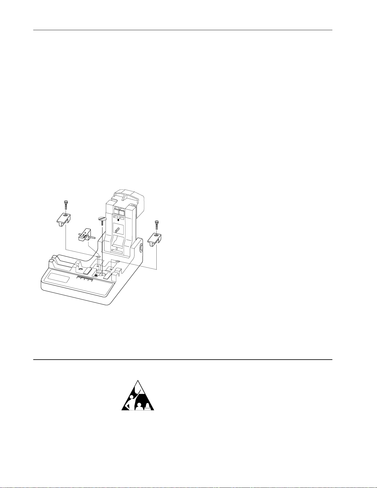
5.3 To change a guide :
a) Use a 2.5 mm hex key to remove the hex-head
cap screw which secures the guide to the cleaver
base (Figure 0).
b) Place the new guide in the base and secure it with
the cap screw. Optionally, the guide may be held in
place by the magnetic base without the securing
screw.
Issue 7 SRP-001-062 Page 3
CAUTION: Never substitute sand paper or other
abrasive papers for the cleaning strips. Doing so will destroy the
polished surface of the anvil and clamps.
EOS
EOS
OptiStrip
OptiStrip
15 10 5
15 10 5
15 10 5
Bare fiber
2.9 mm
jacket 900 µm
15 10 5
EOS
OptiStrip
to here
15105
15 10 5
CUT SLOWLY
CUT SLOWLY
LANGSAM TRENNEN
LANGSAM TRENNEN
Figure 8
15 10 5
Blade
Cleaning strip
Figure 0

Blade Replacement
5.4 If your cleaver begins to perform inconsistently or fails
to make acceptable cuts, first clean the blade as described in
step 5. b.
Check the condition of the blade for damage — if nicks or
other damage to the blade are visible, replace the blade as
described in step 5.5.
5.5 To replace the diamond blade assembly (p/n
FBC-006-0 ):
a) Use a 2.5 mm hex key to remove the screws
from the blade access covers (Figure 9). Lift
the covers out of the cleaver base.
b) Use a slotted screwdriver to remove the slotted
screw which serves as a blade retainer
(Figure ).
c) Use tweezers to remove the old blade assembly.
Figure
d) Clean any dust or fiber fragments from inside
the base of the cleaver.
e) Insert the new blade assembly into the base of
the cleaver. Be sure to properly place its shafts
in the two recesses in the base of the cleaver.
f) Carefully replace the slotted retainer screw
removed in step b and the two covers and
cap screws removed in step a. Do not over
tighten the screws — the blade must be able to
pivot freely.
6. Technical Support
6.1 If the cleaver ever fails to work properly, you may:
• Talk to a Corning Cable Systems Engineer - call
800-743-267 , 8:30 am - 5:00 pm Eastern time.
and ask for the duty enginner.
• Return the cutter for service - contact your Corning
Cable Systems Customer Service Representative at
800-743-267 or the numbers listed below
Page 4 SRP-001-062 Issue 7
Blade
access
cover
Blade
assembly
Retaining
screw
15 10 5
Corning Cable Systems reserves the right to improve, enhance, and modify
the features and specifications of Corning Cable Systems’ products without
prior notification.
All trademarks are the property of their respective holders
Corning Cable Systems is ISO 900 certified.
© 2008 Corning Cable Systems LLC. All rights reserved.
Printed in U.S.A.
Corning Cable Systems
PO Box 489
Hickory, NC 28603-0489 USA
For US and Canada -800-90 -2673
International 828-90 -5000
FAX: 828-90 -5973
http:www.corning.com/cablesystems
Special Note:
Fiber Optic
Training
Program
Corning Cable Systems offers comprehensive, integrated training
programs. Courses are structured for: Telephony, CATV, LAN,
Intelligent Transportation Systems and Power tilities.
For information on Engineering Services Training call: 800-743-2671.
Other CORNING Network Hardware manuals

CORNING
CORNING PCH-96F-01U User manual

CORNING
CORNING EDGE8 Series User manual

CORNING
CORNING Centrix User manual

CORNING
CORNING PS-MP Owner's manual

CORNING
CORNING CCH-01U User manual

CORNING
CORNING ONE SD-LAN User manual

CORNING
CORNING Centrix User manual

CORNING
CORNING Everon 6000 v1.0 User manual

CORNING
CORNING EDGE 1U User manual

CORNING
CORNING CCH-CS User manual

CORNING
CORNING CCH 1U User manual

CORNING
CORNING ONE User manual

CORNING
CORNING Pretium EDGE 01U-RDH User manual

CORNING
CORNING Eclipse 01U User manual

CORNING
CORNING SCRN-510 Manual

CORNING
CORNING ONE User manual

CORNING
CORNING EDGE User manual

CORNING
CORNING Everon 6000 G2 User manual

CORNING
CORNING NI-3012 Reference guide