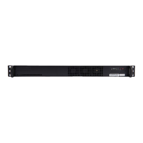
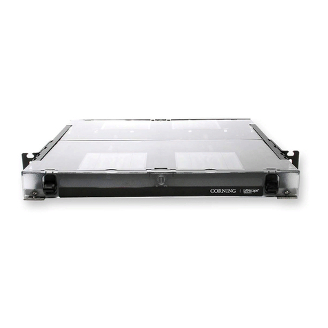
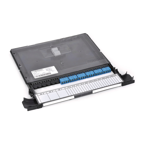
CORNING PCH-96F-01U User manual

003-723, Issue 2
STANDARD RECOMMENDED PROCEDURE 003-723 | ISSUE 2 | OCTObER 2015 | PAGE 1 OF 9
Rack-mountable 1U 96-ber
Housing
related literature | Search www.corning.com/opcomm. Click on “Resources.”
LAN-538-EN Product Specications for Connector Housings
Table of Contents
1. General .................................................................... 2
2. Carton Contents .............................................................. 2
3. Tools and Materials Required ................................................... 3
4. Installation .................................................................. 3
4.1 Opening the Housing ..................................................... 3
4.2 Mounting the Housing into a Rack ........................................... 3
4.3 Installing Cable Entry Plate ................................................. 3
4.4 Securing the Cable ....................................................... 4
4.4.1 Using the Universal Cable Clamp (UCC) ................................ 4
4.4.2 Using Cable Ties ................................................... 4
4.4.3 Strain-relieving the Cable Central Member ............................... 5
4.4.4 Grounding Armored Cable ........................................... 5
4.5 Managing Cable ......................................................... 5
4.5.1 Installing Preconnectorized Cable. . . . . . . . . . . . . . . . . . . . . . . . . . . . . . . . . . . . . . 5
4.5.2 Installing Cable Using Buffer Tube Fanout (BTF) Kits ...................... 6
4.6 Documentation .......................................................... 7
4.7 Closing the Housing ...................................................... 7
4.8 Install Jumpers .......................................................... 8
5. Connector Care and Cleaning ................................................... 8
6. Testing ..................................................................... 9
6.1 Provisioning Tests ........................................................ 9
6.2 Troubleshooting Tests ..................................................... 9

STANDARD RECOMMENDED PROCEDURE 003-723 | ISSUE 2 | OCTObER 2015 | PAGE 2 OF 9
1. General
This document describes the installation of rack-mountable 1U housing with a capacity for 96
bers (Figure 1). The unit ts into 19-inch utility racks and occupies one rack space. Contact
your customer service representative to order other mounting congurations or to purchase
accessories that are sold separately.
Figure 1
2. Carton Contents
Figure 2
• Rack-mountable 1U housing with (2) mounting brackets (Figure 2)
• Hardware Kit containing:
• (1) Unit Identication label
• (2) 10-32 Phillips-head screws
• (1) 6-32 Nylon wing nut
• (2) 6-32 Phillips at-head screws
KPA-0158
KPA-1004
Part Number Dimensions Weight
(H x W x D)
PCH-96F-01U 1.75 x 17 x 12 in. 5 lb (2.3 kg)
(4.5 x 43 x 28.5 cm)
KPA-0159
Removable Identification Panel
Attached to a Flip-down Sliding Tray
Mounting Bracket
Rear Tray Stop
Radius Control Guide
Cable Tie Locations
Radius Control Guide
Mounting
Bracket
Lift-up
Adapter Panel

STANDARD RECOMMENDED PROCEDURE 003-723 | ISSUE 2 | OCTObER 2015 | PAGE 3 OF 9
• (4) Cable ties
• (2 ft) Spiral wrap
• (1 ft) Double-sided hook-and-loop strap
• (1) Internal strain-relief bracket (cable plate)
• (1) Universal Cable Clamp (UCC) kit
• (1) Bracket, right UCC
3. Tools and Materials Required
• Phillips-head screwdriver
• 3/8-inch socket or wrench
• Needle-nosed pliers
• Cable stripping tools
4. Installation
4.1 Opening the Housing
Removing the cover is optional but is recommended to ease installation.
Step 1: Open front and rear doors.
Step 2: Locate the plunger
fasteners at the front of
the unit under the housing
cover and pull out to
release the plungers
(Figure 3).
Step 3: Lift stop latches and
slide the cover of the unit
toward the front until it is
clear of the base. Set the
cover aside.
4.2 Mounting the Housing into a Rack
Attach the unit to the equipment rack using the four screws provided (two screws per side).
4.3 Installing Cable Entry Plate
Step 1: Determine location for cable entry into housing.
Step 2: Slide drawer back completely. The drawer must
be in this position to prevent ber damage during
drawer actuation.
Step 3: Install cable entry plate using the provided wing
nut at the location where the cable will enter the
housing.
Step 4: Install the strain-relief bracket to the side of the
housing (Figure 4) at the location where the cable
will enter the housing.
Figure 4
KPA-0163
Figure 3
KPA-0164

STANDARD RECOMMENDED PROCEDURE 003-723 | ISSUE 2 | OCTObER 2015 | PAGE 4 OF 9
4.4 Securing the Cable
CAUTION: Fiber optic cable is sensitive to excessive pulling, bending, and crushing forces.
Consult the cable specication sheet for the cable you are installing. Do not bend the cable
more sharply than the minimum recommended bend radius. Do not apply more pulling force
to the cable than specied. Do not crush the cable or allow it to kink. Doing so may cause
damage that can alter the transmission characteristics of the cable; the cable may have to be
replaced.
CAUTION: If you are installing outside plant cable or temperature uctuates widely along
any part of the cable, the central member must be strain-relieved. Failure to do so may result
in damage to the cable as temperature varies. If the entire length of cable is located in a
controlled environment where temperature uctuation is minimal, it is not necessary to secure
the central members. The cable can be strain-relieved by sheath retention alone..
To strain-relieve the cable, use the Universal Cable Clamp (UCC) or cable ties.
4.4.1 Using the Universal Cable Clamp (UCC)
Step 1: Attach the UCC clamshell to the strain-relief bracket as shown in Figure 5 to allow
installation of a second UCC if necessary.
Step 2: Follow installation instructions provided with the UCC kit to secure the cable. Do not
tighten yet to allow for cable adjustment if necessary.
Step 3: Secure cable to cable entry plate using a loose cable tie. Do not overtighten cable
tie.
Figure 5
4.4.2 Using Cable Ties
Step 1: Attach the cable with cable ties to the strain-relief bracket in two places as shown in
Figure 6.
Step 2: Allow room on the bracket to strain-relieve the cable strength member, if present.
Step 3: Secure cable to cable entry plate using a loose cable tie. Do not overtighten cable
tie.
KPA-0165

STANDARD RECOMMENDED PROCEDURE 003-723 | ISSUE 2 | OCTObER 2015 | PAGE 5 OF 9
Figure 6
4.4.3 Strain-relieving the Cable Central Member
Step 1: Install the U-shaped washer and the at washer on the strain-relief bracket in the
orientation shown in Figure 6 using the supplied Phillips-head screw.
Step 2: Place the central member and yarn, if present, between the U-shaped washer and
the at washer.
Step 3: Wrap yarn in a clockwise direction around the screw and under the U-shaped
washer.
Step 4: Tighten the screw.
Step 5: Trim off the excess yarn and central member.
4.4.4 Grounding Armored Cable
One grounding kit (p/n FDC-CABLE-GRND, purchased separately) is required to ground each
armored cable. Follow instructions provided with the grounding kit.
Step 1: Attach the other end of the ground wire to the equipment rack. The equipment rack
must be grounded to the primary building ground.
Step 2: Remove the paint from the frame at the grounding location to ensure metal-to-
metal contact. It is recommended to use an antioxidant on the bare metal to prevent
corrosion.
Step 3: Or, attach the other end of the ground wire to a rack-mounted grounding bus bar,
which is grounded to the primary building ground.
4.5 Managing Cable
4.5.1 Installing Preconnectorized Cable
WARNING: Never look directly into the end of a ber that may be carrying laser light.
Laser light can be invisible and can damage your eyes. Viewing it directly does not cause pain.
The iris of the eye will not close involuntarily as when viewing a bright light. Consequently,
serious damage to the retina of the eye is possible. Should accidental eye exposure to laser
light be suspected, arrange for an eye examination immediately.
KPA-0167
Cable ties
Yarn (if present)
Central member
Flat washer
U-shaped washer

STANDARD RECOMMENDED PROCEDURE 003-723 | ISSUE 2 | OCTObER 2015 | PAGE 6 OF 9
WARNING: DO NOT use magniers in the presence of laser radiation. Diffused laser light
can cause eye damage if focused with optical instruments. Should accidental eye exposure to
laser light be suspected, arrange for an eye examination immediately.
Step 1: Clean connectors and adapters as described in Section 5.
Step 2: Install connectors into the adapters at the rear of the connector panels.
Step 3: Route cable slack around radius control guides (Figure 7).
Step 4: Use cable ties through the lances to secure bers as needed.
IMPORTANT: Lift the tray stop latches and slide the drawer backward and forward to verify that the
drawer slides in the grooves of the guides and that there is enough ber slack to prevent
violating the minimum ber bend radius of the cable.
Figure 7
4.5.2 Installing Cable Using Buffer Tube Fanout (BTF) Kits
CAUTION: Corning recommends the use of safety glasses (spectacles) conforming to ANSI
Z87 for eye protection from accidental injury when handling chemicals, cables, or working with
ber. Pieces of glass ber are very sharp and have the potential to damage the eye.
CAUTION: The wearing of cut-resistant safety gloves to protect your hands from accidental
injury when using sharp-bladed tools and armored cable is strongly recommended. Use
extreme care when working with severed armor. There will be a sharp edge where armor is
cut. To minimize the chance of injury from the cut armor, cover the exposed edge with a wrap
of electrical tape. To minimize the chance of injury from sharp-bladed tools, always cut away
from yourself and others. Dispose of used blades and armor scrap properly.
Step 1: Terminate the bers according to the instruction provided with the BTF kit.
Step 2: Feed the fanout body and connectors through the cable entry opening.
Step 3: Slide the drawer back completely and loop the buffer tube under the fanout bracket
and around the radius control guides. Secure the BTF truck body to the fanout
bracket using a cable tie (Figure 8).
KPA-0160
Cable Ties
Cable Ties
Tray Stop Latch
Tray
Stop
Latch
Cable Ties

STANDARD RECOMMENDED PROCEDURE 003-723 | ISSUE 2 | OCTObER 2015 | PAGE 7 OF 9
Step 4: Route the connectorized bers under the plastic tabs on the radius control guides.
Step 5: Remove dust caps from the connectors and adapters into which they will be mated.
Refer to Section 5 for recommended cleaning procedures or clean the connector
end-faces and the adapter per standard company practices. Mate the connectors in
the adapters.
Step 6: Use cable ties through the lances to secure bers as needed.
Figure 8
4.6 Documentation
Record ber identication information appropriately on the identication label (Figure 9). The
identication panel can be removed, if desired. Accurate recordkeeping is imperative for an
organized installation.
Figure 9
4.7 Closing the Housing
Step 1: Lift up on stop latches and slide drawer forward to make sure cable is not stressed.
If necessary, readjust cable strain-relief to prevent stress on bers. Tighten UCC
clamp.
Step 2: Slide drawer back to original position.
Step 3: If previously removed, slide the cover back in the retaining anges on top of the
housing. Push the plunger fasteners to secure.
Step 4: Close the front and rear doors.
KPA-0161
KPA-1006

STANDARD RECOMMENDED PROCEDURE 003-723 | ISSUE 2 | OCTObER 2015 | PAGE 8 OF 9
4.8 Install Jumpers
Step 1: Remove dust caps from the connectors and adapters into which they will be mated.
Refer to Section 5 for cleaning instructions or clean connector end-faces and
adapters per standard company practices and insert connectors into adapters.
Step 2: Install jumpers as specied on planning diagrams. The panel can be raised to access
the adapters on the bottom row. When raising the panel, the cover must be removed
to prevent damage to the connectors on the back side of the panel. Cut the provided
hook-and-loop strap into small sections and feed the strap through the appropriate
lance at the front of the housing. Loosely secure jumpers using the straps at the front
of the housing (Figure 10).
Figure 10
Step 3: Provide enough jumper slack to allow the connector panel tray to slide backward and
forward without violating the minimum bend radius of the jumper.
Step 4: Record jumper routing information on the provided identication label. The
identication panel can be removed, if desired. Accurate recordkeeping is imperative
for an organized installation.
5. Connector Care and Cleaning
WARNING: Isopropyl alcohol is ammable with a ashpoint at 54ºF. It can cause irritation to
eyes on contact. In case of contact, ush eyes with water for at least 15 minutes. Inhalation
of vapors irritates the respiratory tract. Exposure to high concentrations has a narcotic effect,
producing symptoms of dizziness, drowsiness, headache, staggering, unconsciousness and
possibly death.
• Always keep dust caps on connectors and adapters when not in use.
• Ensure dust caps are clean before reuse.
• Use optical cleaning materials as standardized by your company.
• Clean the connector before every mating, especially for test equipment patch cords
(jumpers).
• A minimum level of cleaning is listed below. Local procedures may require more rigorous
cleaning methods.
Step 1: Remove plugs from the connector adapter.
Step 2: Wipe the connector ferrule twice with a lint-free wiping material moistened with
isopropyl alcohol. Then wipe across the end of the ferrule.
Step 3: Repeat previous step with a dry wipe.
KPA-1023

STANDARD RECOMMENDED PROCEDURE 003-723 | ISSUE 2 | OCTObER 2015 | PAGE 9 OF 9
Corning Optical Communications LLC • PO Box 489 • Hickory, NC 28603-0489 USA
800-743-2675 • FAX: 828-325-5060 • International: +1-828-901-5000 • www.corning.com/opcomm
Corning Optical Communications reserves the right to improve, enhance, and modify the features and specications of Corning Optical Communications products
without prior notication. A complete listing of the trademarks of Corning Optical Communications is available at www.corning.com/opcomm/trademarks. All other
trademarks are the properties of their respective owners. Corning Optical Communications is ISO 9001 certied. © 2007, 2015 Corning Optical Communications.
All rights reserved.
6. Testing
6.1 Provisioning Tests
Equipment should be tested from the source (or central ofce) to receiver at the time of
provisioning to verify signal continuity and acceptable loss limits. Use an optical power meter to
verify signal continuity and determine loss measurements are within specied local standards.
6.2 Troubleshooting Tests
An optical power meter can be used to perform the rst step in troubleshooting. A power meter
designed for measuring only dBm power levels is suitable for maintenance purposes.
For high attenuation:
• Remove connector and reclean connector and adapter.
• Verify cable ties are not too tight.
• Maintain appropriate ber bend radius. Make sure there are no sharp bends.
Once a fault is isolated to the installed cable link, an OTDR (Optical Time Domain
Reectometer) is needed. An OTDR can locate ber events and measure the losses attributable
to cable, connectors, splices, and/or other components. The graphical display of loss over a
cable’s entire length provides the most revealing analysis and documentation available on a
cable link, commonly referred to as its signature trace. Corning Cable Systems recommends
performing an OTDR analysis to document the integrity of the cable system, locate and
measure each event or component, and uncover faults throughout the cable. Follow the
instructions provided with the OTDR tester you are using.
Table of contents
Other CORNING Network Hardware manuals
CORNING
CORNING ONE SD-LAN User manual

CORNING
CORNING ONE User manual

CORNING
CORNING EDGE User manual

CORNING
CORNING EDGE8 Series User manual

CORNING
CORNING CCH-01U User manual

CORNING
CORNING Everon 6000 G2 User manual
CORNING
CORNING PS-MP Owner's manual

CORNING
CORNING SCRN-510 Manual
CORNING
CORNING ONE User manual

CORNING
CORNING EDGE 1U User manual

CORNING
CORNING Centrix User manual

CORNING
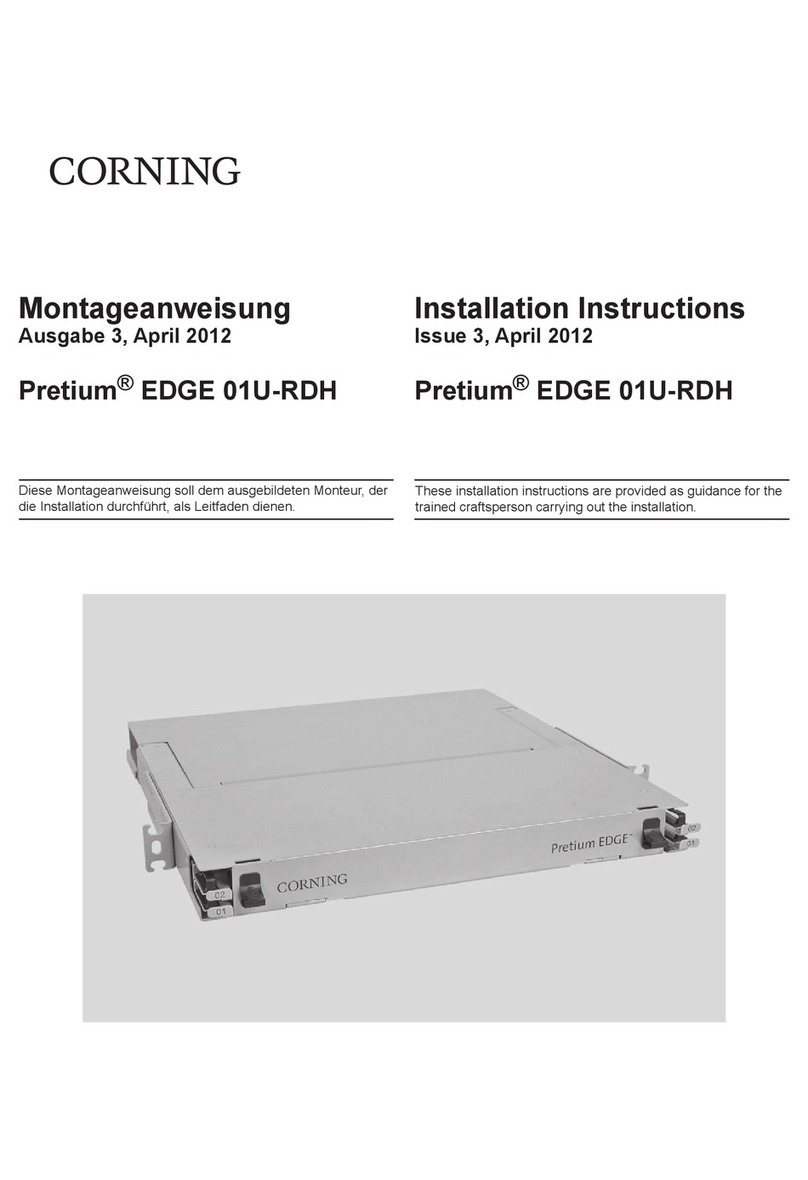
CORNING Pretium EDGE 01U-RDH User manual

CORNING
CORNING FBC-006 User manual

CORNING
CORNING Everon 6000 v1.0 User manual

CORNING
CORNING NI-3012 Reference guide
CORNING
CORNING CCH-CS User manual

CORNING
CORNING Eclipse 01U User manual
CORNING
CORNING Centrix User manual
CORNING
CORNING CCH 1U User manual