manuals.online logo
Brands
  1. Home
  2. •
  3. Brands
  4. •
  5. CORNING
  6. •
  7. Network Hardware
  8. •
  9. CORNING Pretium EDGE 01U-RDH User manual

CORNING Pretium EDGE 01U-RDH User manual

Installation Instructions
Issue 3, April 2012
Pretium®EDGE 01U-RDH
Montageanweisung
Ausgabe 3, April 2012
Pretium®EDGE 01U-RDH
These installation instructions are provided as guidance for the
trained craftsperson carrying out the installation.
Diese Montageanweisung soll dem ausgebildeten Monteur, der
die Installation durchführt, als Leitfaden dienen.
2Pretium® EDGE (Evolved-Density, Growth-Enabled) 01U-RDH
Contents
1. General
2. Carton contents
3. Tools and materials required
4. Installation
5. Cable routing
6. Troubleschooting and maintaince
7. Connector care and cleaning
1. General
This document describes installation of Pretium®EDGE
1U-RDH short into the frame in cabinet.
2. Carton Contents
· Housing 1U rack-height
· Mounting hardware kit for rack or frame
installation
3. Tools and Materials Required
· Phillips-head screwdriver
· Hook-and-loop straps
· LC Connector / Adapter Cleaning Tool (p/n)
CLEANER-PORT-LC)
· MTP® Connector Cleaning Cassette (p/n
CLEANER-UNIV-CASS)
· MTP Adapter Cleaning Tool
Inhalt
1. Allgemeines
2. Packungsinhalt
3. Benötigtes Werkzeug und Material
4. Installation
5. Kabelführung
6. Fehlerbehebung und Wartung
 7. PegeundReinigungderStecker
1. Allgemeines
Das vorliegende Dokument beschreibt die Installation
des kurzen Pretium®EDGE 01U-RDH im Schrankrah-
men.
2. Packungsinhalt
· 1HE-Gehäuse
· Einbau-Set für den Schrank- bzw.
Rahmeneinbau
3. Benötigtes Werkzeug und Ma-
terial
· Kreuzschlitzschraubendreher
· Klettstreifen
· Reinigungsgerät für LC-Stecker/Adapter (Artikelbe-
zeichnung: CLEANER-PORT-LC)
· Reinigungskassette für MTP®-Stecker (Artikelbe-
zeichnung: CLEANER-UNIV-CASS)
· Reinigungsgerät für MTP-Adapter
Pretium® EDGE (Evolved-Density, Growth-Enabled) 01U-RDH 3
4. Installation
4.1 Mount Housing
a) Identify the position on the rack
where the housing will be installed.
b) Attach housing to frame in cabinet
4.1.1 Mount Trunk Cables in the
Housing
a) Pull trunk cables to the frame per
the instructions provided with cables.
b) Open rear housing door. Route
cables into housing through side
openings.
c) Attach cables to the housing with
trunkholder.
d) Repeat for all trunk cables and
allowlegstoowouttherearofthe
housing until ready to clean and mate
in the appropriate module or panel.
RDH_0002
RDH_0005
4. Installation
4.1 Montieren des Gehäu-
ses
a) Legen Sie fest, wo im Schrank das
Gehäuse eingebaut werden soll.
b) Befestigen Sie das Gehäuse am
Schrankrahmen
4.1.1 Montieren der Multifaserkabel
im Gehäuse
a) Ziehen Sie die Multifaserkabel wie
in der den Kabeln beiliegenden Be-
schreibung erläutert in den Rahmen.
b) Öffnen Sie die Tür auf der Gehäu-
serückseite und führen Sie die Kabel
durch die Öffnungen seitlich in das
Gehäuse.
c) Befestigen Sie die Kabel mit Hilfe
von Kabelhaltern am Gehäuse.
d) Wiederholen Sie diese Schritte
für alle Multifaserkabel und lassen
Sie die Adern auf der Rückseite des
Gehäuses heraushängen, bis diese in
einem weiteren Schritt gereinigt und in
das entsprechende Modul oder Feld
eingesteckt werden.
RDH_0031
4Pretium® EDGE (Evolved-Density, Growth-Enabled) 01U-RDH
RDH_0007
4.2 Install EDGE Modules
Option 1
a) Open and lower front door.
b) Using lowered front door for leve-
rage, lift and pull drawer horizontally
until reaching hard stops. Place a
hand under the tray to prevent the tray
from dropping suddenly.
c) Lower the drawer to the angled
position.
d) Remove module adapter dust co-
vers. Clean connectors and adapters
using the appropriate cleaning tool.
Follow the instructions provided with
each tool.
e) Mate the MTP connector into the
adapter at the back of the module.
f) From rear housing, feed connecto-
rized MTP connector through to the
front of the housing.
g) Starting with the lower left corner
(Tray 1, slot A, as seen from the front),
insert the module from the rear until it
locks into place.
h) Repeat for all modules.
i) The slide and tilt mechanism should
only be used for initial install. For sub-
sequent Moves, Adds and Changes,
only the sliding trays should be activa-
ted, as with the 4U housing, while the
sliding and tilting shelf should remain
in closed position.
RDH_0028
4.2 Installieren der
EDGE-Module
Variante 1
a) Öffnen Sie die Frontklappe und
klappen Sie sie nach unten.
b) Verwenden Sie die offene Klap-
pe als Griff, um den Auszug etwas
anzuheben und waagrecht bis zum
Endanschlag herauszuziehen. Fassen
Sie die Kassette dabei mit einer Hand
von unten, so dass sie nicht abrupt
herabfällt.
c) Senken Sie den Auszug vorsichtig
in die schräge Stellung ab.
d) Entfernen Sie den Staubschutz von
den Moduladaptern. Reinigen Sie die
Stecker und Adapter mit dem geeig-
neten Reinigungsgerät. Beachten
Sie dabei die dem Gerät beiliegende
Anleitung.
e) Stecken Sie den MTP-Stecker in
den Adapter hinten am Modul ein.
f) Führen Sie den konfektionierten
MTP-Stecker von der Rückseite des
Gehäuses nach vorne.
g) Schieben Sie das Modul von hinten
her ein, bis es einrastet. Beginnen Sie
dabei in der von vorne gesehen un-
teren linken Ecke (Kassette 1, Schlitz
A).
h) Wiederholen Sie diese Schritte für
alle Module.
i) Der Schiebe- und Kippmechanismus
sollte nur im Rahmen der Erstmontage
verwendet werden. Für darauffolgende
Bewegungen, Änderungen etc. sollten
ausschließlich die Kassetten wie beim
4HE-Gehäuse aktiviert werden, wobei
die Ablage in geschlossener Position
verbleiben sollte.
Pretium® EDGE (Evolved-Density, Growth-Enabled) 01U-RDH 5
Option 2
a) Remove rear lid.
b) From rear housing, mate the con-
nectorized MTP connector into the
adapter at the back of the module.
c) Starting with the lower left corner
(Tray 1, slot A, as seen from the front),
insert the module from the rear until it
locks into place.
h) Repeat for all modules.
4.3 Connect Jumpers to
EDGE Module
ATTENTION: During the jumper
installation, remember to leave
excess of cable, to avoid damage
while pulling the drawer to the an-
geled position.
a) Open housing front door and pull
out tray.
b) Clean the shuttered LC adapters
using the CLEANER-PORT-LC tool.
Follow the instructions provided with
the tool.
c) Remove dust covers from LC
connectors on the jumper cables.
Clean the connector endfaces using the
CLEANER-PORT-LC tool.
d) Mate the connectors in the adap-
ters.
e) Route jumper legs, right and/or left
out either side of the housing. (Do
NOT cross legs in opposite direc-
tions.) Store legs in clips at front of
tray.
f) Route the jumper legs per your
installationplantotheirnaldestina-
tions.
g) Repeat for remaining jumpers.
RDH_0009
Variante 2
a) Nehmen Sie den Deckel auf der
Gehäuserückseite ab.
b) Stecken Sie auf der Rückseite des
Gehäuses den konfektionierten MTP-
Stecker in den Adapter hinten am
Modul ein.
c) Schieben Sie das Modul von hinten
her ein, bis es einrastet. Beginnen Sie
dabei in der von vorne gesehen un-
teren linken Ecke (Kassette 1, Schlitz
A).
h) Wiederholen Sie diese Schritte für
alle Module.
4.3 Anschließen von Jum-
pern an EDGE-Module
ACHTUNG: Achten Sie beim Ein-
bau der Jumper darauf, etwas
Kabelüberlänge zu belassen, um
Schäden beim Herausziehen der
Kassette in die abgesenkte schräge
Stellung zu verhindern.
a) Öffnen Sie die Frontklappe und
ziehen Sie die Kassette heraus.
b) Reinigen Sie die verschlossenen
LC-Adapter mit dem CLEANER-
PORT-LC Reinigungsgerät. Beachten
Sie dabei die dem Gerät beiliegende
Anleitung.
c) Entfernen Sie den Staubschutz von
den LC-Steckern an den Jumperka-
beln.ReinigenSiedieStirnächender
Stecker mit dem CLEANER-PORT-LC
Reinigungsgerät.
d) Stecken Sie die Stecker in die
Adapter ein.
e) Führen Sie die Jumperkabel wahl-
weise nach rechts und/oder links aus
dem Gehäuse. (Kabel NICHT über
Kreuz führen!). Führen Sie die Kabel
durch die Halteclips vorne an der
Kassette.
f) Führen Sie die Jumperkabel wie im
Installationsplan vorgesehen an ihr
Anschlussziel.
g) Wiederholen Sie diese Schritte für
alle weiteren Jumper.
6Pretium® EDGE (Evolved-Density, Growth-Enabled) 01U-RDH
4.4 Install MTP® Adapter
Panels
Adapter panels may be installed
from the front or back of the EDGE
housing. During the initial installati-
on, it is recommended to install the
panels from the rear of the housing. It
is recommended to install trunk cables
into ALL of the adapters at the initial
installation to avoid the possibility of
pullingonberslegsorofdisrupting
service that may occur when the
panel is moved to install additional
connectors.
TheMTPadapterpaneliscongured
in four variations to support 24- and
48-berrequirementsInbothsingle-
mode (SM) and Multimode (MM)
applications. Adapters have been
clearlylabeledidentifyingbers(for
example, 1-12, 13-24, 25-36, and
37-48) and ports (1, 2, 3, or 4). The
24-berversionisequippedwithtwo
12-berMTPadapters;the48-ber
versionhasfour12-berMTPadap-
ters. Each tray within the housing will
support a maximum of 16 2.9mm legs,
if using the fouradapter MTP panel for
maximum density. (For illustrative pur-
poses, the four-adapter panel is show
intheaccompanyinggures.)
4.4.1 Initial Panel Installation
a) Remove MTP connector and rear
panel adapter dust covers. Clean
connectors and adapters using the
appropriate cleaning tool. Follow the
instructions provided with the tool.
b) Mate the MTP connector(s) into the
rear of the adapter(s).
c) Repeat for the remaining adapters
and connectors.
d) From the rear of the housing or
with opened drawer, starting with
lower right corner (Tray 1, slot A)
insert panel from the rear until it locks
into place. Load all panels from right
to left, bottom to top in the housing as
seen from the rear.
e) Repeat for all panels.
f)Looselycaptureberslackwith
hook-and-loop straps in the same
manner as illustrated for the MDA
housing.
4.4 Installieren der
MTP®-Adapterfelder
Adapterfelder können von der Vorder-
oder Rückseite des EDGE-Gehäuses
her eingebaut werden. Beim Ersteinbau
wird empfohlen, die Felder von der
Gehäuserückseite her einzubauen. Wir
empfehlen, schon jetzt Multifaserkabel
an ALLE Adapter anzuschließen, um
nicht beim späteren Herausnehmen des
Feldes zum nachträglichen Anschluss
von Steckern versehentlich Adern
herauszuziehen oder Betriebsunterbre-
chungen zu verursachen.
Das MTP-Adapterfeld ist in vier Kon-
gurationsvariantenerhältlich,die24
und 48 Fasern in Singlemode (SM)-
und Multimode (MM)-Anwendungen
unterstützen. An den Adaptern sind die
Fasern (z. B. 1-12, 13-24, 25-36, und
37-48) und Ports (1, 2, 3, oder 4) ein-
deutig beschriftet. Die Ausführung für
24 Fasern umfasst zwei 12-Faser-MTP-
Adapter;dieAusführungfür48Fasern
umfasst vier 12-Faser-MTP-Adapter.
Beim MTP-Feld mit vier Adaptern für
maximale Belegungsdichte unterstützt
jede Kassette im Gehäuse max. 16 2,9
mm-Adern. (Zu Illustrationszwecken ist
hier das Adapterfeld mit vier Adaptern
gezeigt.)
4.4.1 Ersteinbau des Felds
a) Entfernen Sie den Staubschutz von
den MTP-Steckern und Adaptern auf
der Rückseite des Felds. Reinigen Sie
Stecker und Adapter mit dem geeig-
neten Reinigungsgerät. Beachten
Sie dabei die dem Gerät beiliegende
Anleitung.
b) Stecken Sie den/die MTP-Stecker
auf der Rückseite in den/die Adapter
ein.
c) Wiederholen Sie diese Schritte für
alle weiteren Stecker und Adapter.
d) Schieben Sie von der Rückseite des
Gehäuses her bzw. bei geöffnetem
Auszug das Feld von hinten her ein,
bis es einrastet. Beginnen Sie dabei in
der unteren rechten Ecke (Kassette 1,
Schlitz A). Setzen Sie alle Felder in der
Reihenfolge von rechts nach links und
von unten nach oben (von der Rücksei-
te aus gesehen) in das Gehäuse ein.
e) Wiederholen Sie diese Schritte für
alle Felder.
f) Sichern Sie Faserüberlängen wie
beim MDA-Gehäuse gezeigt locker mit
Klettstreifen.
Pretium® EDGE (Evolved-Density, Growth-Enabled) 01U-RDH 7
4.4.2. Adding Trunk Cables to
Previously Installed MTP Adap-
ter Panels
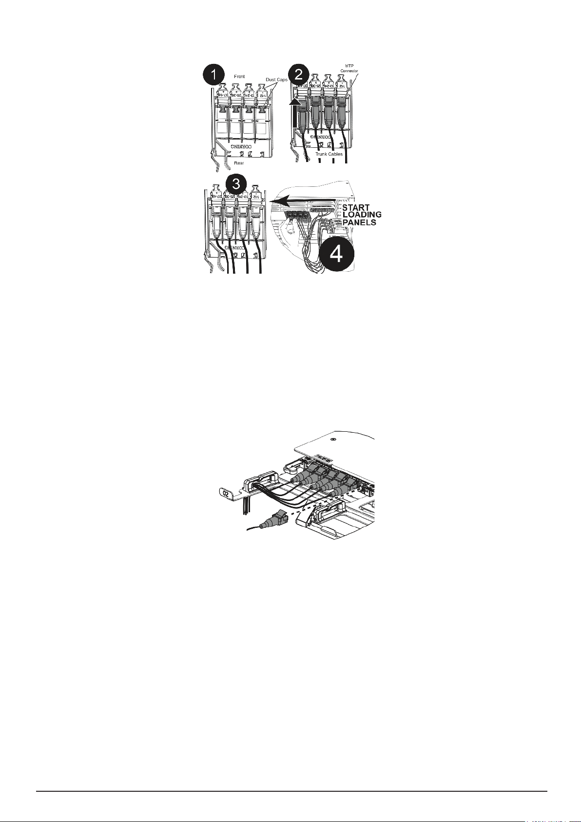
a) From the rear of the housing, locate
the unused MTP adapter panel. With the
dust cover in place on the connector, feed
the MTP connector and trunk through the
opening in the back of the MTP panel.
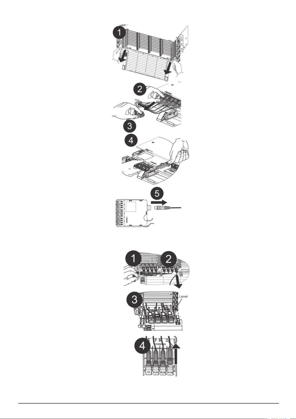
b) From the front of the housing, open the
door.Usingthengertabsonthesidesof
the tray, pull out the tray with the unused
adapter panel to the detent position.
c) Remove previously terminated har-
nesses from the tray routing clips and, if
possible, disconnect the harness from the
MTP panel where the termination is to be
added to create slack in the harness and
allow panel to slide forward.
d) Press on the latch to the right of the
panel and pull the panel out as far as pos-
siblewithoutpullingonthebersalready
connected on the front and back sides of
the adapter.
e) Lift out the MTP connector from the
back of the panel. Remove the connector
and adapter dust covers. Clean connec-
tors and adapters using the appropriate
cleaning tool. Follow the instructions
provided with the tool.
f) Mate the connector into the rear of the
adapter as shown.
g) Slide panel back until it locks into positi-
on. Replace and re-route any harnesses in
the tray routing clips, as shown in the next
section, that may have been previously
removed.
h) Slide the tray back into the housing.
4.4.3 Connect Wiring Harnesses
to MTP Adapter Panels
a) Open housing front door and pull out
tray.
b) Remove dust covers from the adap-
ter, if applicable, and the MTP connector
on the wiring harness. Clean the con-
nector and adapter with the appropriate
cleaning tool.
c) Mate the connectors in the adapters.
d) Route the harness cable either to
the right and/or to the left and out either
side of the housing. (Do NOT cross legs
in opposite directions.) Store the legs
intheberclipsatthefrontofthetray.
Close the tray.
e) Clean the connectors at the end
of the wiring harness and mate in the
electronics equipment per instructions
provided with that equipment or accor-
ding to your installation plan.
4.4.2. Hinzufügen von Multifa-
serkabeln zu bereits installier-
ten MTP-Adapterfeldern
a) Machen Sie auf der Rückseite des Ge-
häusesdenfreienMTP-Adapterausndig.
Führen Sie den MTP-Stecker mit aufge-
setztem Staubschutz samt Multifaserkabel
durch die Öffnung auf der Rückseite des
MTP-Felds.
b) Öffnen Sie die Frontklappe. Ziehen Sie
die Kassette mit dem freien Adapterfeld
an den Griffzapfen seitlich an der Kassette
bis zum Anschlag heraus.
c) Lösen Sie die zuvor terminierten Ka-
belbäume aus den Führungsclips in der
Kassette und trennen Sie, wenn möglich,
den Kabelbaum dort, wo die Terminierung
hinzugefügt werden soll, vom MTP-Feld
ab, um eine Überlange im Kabelbaum zu
erhalten und das Feld nach vorne ziehen
zu können.
d) Drücken Sie die Zunge rechts vom Feld
ein und ziehen Sie das Feld so weit wie
möglich heraus, ohne an den bereits an
der Vorder- und Rückseite des Adapters
angeschlossenen Fasern zu zerren.
e) Heben Sie den MTP-Stecker aus der
Rückseite des Felds heraus. Entfernen
Sie den Staubschutz von Stecker und
Adapter.
Reinigen Sie Stecker und Adapter mit
dem geeigneten Reinigungsgerät. Beach-
ten Sie dabei die dem Gerät beiliegende
Anleitung.
f) Stecken Sie den Stecker wie gezeigt auf
der Rückseite des Adapters ein.
g) Schieben Sie das Feld wieder zurück,
bis es einrastet. Führen Sie alle zuvor
gelösten Kabelbäume wieder durch die
Führungsclips in der Kassette, wie im
nächsten Abschnitt gezeigt.
h) Schieben Sie dann die Kassette wieder
in das Gehäuse.
4.4.3 Anschließen der Kabelbäu-
me an die MTP-Adapterfelder
a) Öffnen Sie die Frontklappe und ziehen Sie
den Auszug heraus.
b) Entfernen Sie den Staubschutz vom
Adapter (sofern zutreffend) und dem MTP-
Stecker am Kabelbaum. Reinigen Sie
Stecker und Adapter mit dem geeigneten
Reinigungsgerät.
c) Stecken Sie die Stecker in die Adapter
ein.
d) Führen Sie die Kabel wahlweise nach
rechts und/oder links aus dem Gehäuse.
(Kabel NICHT über Kreuz führen!). Führen
Sie die Kabel durch die Halteclips vorne an
der Kassette. Schließen Sie die Kassette.
e) Reinigen Sie die Stecker am Ende des
Kabelbaums und stecken Sie diese in die
elektronischen Geräte ein, wie in den zuge-
hörigen Gerätebeschreibungen erklärt bzw.
wie in Ihrem Installationsplan vorgesehen.
8Pretium® EDGE (Evolved-Density, Growth-Enabled) 01U-RDH
5. Recomended cable
routings
Ensure that the spiral wrap covering
the trunk legs is 50cm long, and that
the legs contained are not twisted
or crossed. The spiral wrap section
needs to form one complete loop in
the rear of the housing.
NOTE: If the spiral wrap is subject to
tension, simply remove the parked
trunk and rotate the furcation plug to
allow the spiral wrap to fall back to its
natural position.
5. Empfohlene Kabel-
führung
Stellen Sie sicher, dass der Spi-
ralschlauch, der die Adern umgibt, 50
cm lang ist und dass die Adern nicht
verdreht oder gekreuzt werden. Der
Spiralschlauchteil sollte eine vollstän-
dige Schleife im hinteren Bereich des
Gehäuses bilden.
HINWEIS: Wenn auf dem Spi-
ralschlauch Zug lastet, lösen Sie das
Multifaserkabel und drehen Sie den
Verzweigungsstecker, sodass der
Spiralschlauch in seine natürliche
Position zurückfallen kann.
Pretium® EDGE (Evolved-Density, Growth-Enabled) 01U-RDH 9
6. Troubleshooting
and Maintenance
6.1 Replace EDGE Module
a) Open front door and pull tray out.
b) Press latch on LC connector and
pull connector out.
c) Press lever on right of module and
pull module out.
d) Unplug MTP connector in rear of
module.
e) Reverse process to install new
module (or panel, if upgrading the
network).
6.2 Replace MTP Adapter
Panel
a) Open front door and pull tray out.
b) Unplug MTP connectors from front
of panel.
c) Press lever on right of module and
pull module out.
d) Unplug MTP connectors in rear of
adapters.
e) Reverse process to install new
panel (or module).
RDH_0011
6. Fehlerbehebung
und Wartung
6.1 Austauschen von
EDGE-Modulen
a) Öffnen Sie die Frontklappe und
ziehen Sie die Kassette heraus.
b) Drücken Sie die Zunge am LC-
Stecker ein und ziehen Sie den Stek-
ker heraus.
c) Drücken Sie den Hebel rechts vom
Modul nieder und ziehen Sie das
Modul heraus.
d) Stecken Sie den MTP-Stecker
hinten am Modul ab.
e) Führen Sie die vorstehenden
Schritte in umgekehrter Reihenfolge
aus, um das neue Modul (bzw. Feld,
wenn das Netzwerk erweitert wird) zu
installieren.
6.2 Austauschen der
MTP®-Adapterfelder
a) Öffnen Sie die Frontklappe und
ziehen Sie die Kassette heraus.
b) Stecken Sie die MTP-Stecker vor-
ne am Feld ab.
c) Drücken Sie den Hebel rechts vom
Modul nieder und ziehen Sie das
Modul heraus.
d) Stecken Sie die MTP-Stecker hin-
ten von den Adaptern ab.
e) Führen Sie die vorstehenden
Schritte in umgekehrter Reihenfolge
aus, um das neue Feld (oder Modul)
zu installieren.
10 Pretium® EDGE (Evolved-Density, Growth-Enabled) 01U-RDH
6.3 Remove Trunk Cable
If necessary to replace trunk cable
or cradle, remove per the directions
in this section.
Install new cable or cradle per the
directions in proper sections.
a) Push on the latch as shown. Lift
cradle and cable up.
b) Simultaneously push the trunk both
ways as show.
c) Push it from the bottom using your
forengeratthesametime.
RDH_0021
6.3 Entfernen von Multifa-
serkabeln
Bauen Sie Multifaserkabel oder
-halter, die ausgetauscht werden
müssen, wie hier beschrieben aus.
Installieren Sie dann das neue
Kabel bzw. die neue Halterung
wie im entsprechenden Abschnitt
beschrieben.
a) Drücken Sie die Zunge wie gezeigt
ein und heben Sie Halterung und
Kabel an.
b) Drücken Sie das Multifaserkabel
wie gezeigt zugleich nach vorne und
oben.
c) Schieben Sie es gleichzeitig mit
demZeigengernachobenheraus.
RDH_0034
RDH_0033
Pretium® EDGE (Evolved-Density, Growth-Enabled) 01U-RDH 11
Option 1
Take out the trunkholder from
hardware (6.3, point a and b).
Insert screwdriver into the hole shown
at the picture and lever up the plug.
Option 2
For easier trunk replacemen ope-
ration, unscrew the screw with the
Phillips-head screwdriver. Slide out
the trunkholder as shown on the
picture.
Remove trunk according to directions
in Section 6.3. Slide backe the trunk
holder and screw back the Philips
screw.
RDH_0022
Schieben
RDH_0025
RDH_0028
Variante 1
Lösen Sie den Kabelhalter aus seiner
Unterbringung und halten Sie ihn mit
einer Hand (6.3, a und b).
Stecken Sie einen Schraubendreher in
die im Bild gezeigte Öffnung und hebeln
Sie den Stecker nach oben heraus.
Variante 2
Noch leichter lässt sich das Multifa-
serkabel austauschen, wenn Sie die
Schraube mit einem Kreuzschlitz-
schraubendreher herausdrehen. Ziehen
Sie dann den Kabelhalter wie im Bild
gezeigt heraus.
Bauen Sie das Multifaserkabel wie un-
ter 6.3. beschrieben aus. Schieben Sie
dann den Kabelhalter wieder ein und
sichern Sie ihn wieder mit der Kreuz-
schlitzschraube.
Corning Cable Systems GmbH & Co. KG
© CORNING CABLE SYSTEMS Polska Sp. z o.o. ,
Smolice 1E, 95-010 Strykow / Poland
Tel. +48 (42) 230 11 00 Fax: 48 (42) 230 11 01
Internet: www.corning.com/cablesystems
Gedruckt in der Bundesrepublik Deutschland auf sauerstoffgebleichtem Papier.
Printed in the Federal Republic of Germany on oxygen-bleached paper.
Liefermöglichkeiten und technische Änderungen vorbehalten.
Subjecttoavailability.Rightofmodicationreserved.
Best.-Nr.:
Order No.:
24.02. 2010
S46998-L5505-P420
Haftungsausschluss
Die Corning Cable Systems GmbH & Co. KG haftet nicht
für Schäden, die durch den nicht bestimmungsgemäßen
Gebrauch des Produktes entstehen.
Im einzelnen ergibt sich der Haftungsumfang aus
den Allgemeinen Verkaufsbedingungen der
Corning Cable Systems GmbH & Co. KG.
Dieses Produkt entspricht dem heutigen Stand
der Technik!
Entsorgungshinweis
Die örtliche und aktuell gültige Gesetzgebung ist bei der
Entsorgung der Produkte und deren Verpackung
unbedingt zu beachten!
Disclaimer
Corning Cable Systems GmbH & Co. KG accepts no
liability for any damage arising from improper use of the
product.
Theextentofanyliabilityinspecicinstancesshallbe
limited to the General Terms and Conditions of Sale from
Corning Cable Systems GmbH & Co. KG.
This product is state of the current art.
Disposal Note
Disposal of the products and their packaging must
be carried out in strict compliance with the local laws
currently in force.
6. Connector Care
and Cleaning
Clean connectors and adapters using
the recommended cleaning tools or
kits for the connector type.
•Alwayskeepdustcapsonconnec-
tors and adapters when not in use.
•Ensuredustcapsarecleanbefore
reuse.
•Cleantheconnectorbeforeevery
mating, especially for test equipment
patch cords (jumpers).
6. Pege und Reini-
gung der Stecker
Reinigen Sie die Stecker und Adapter
mit den für den jeweiligen Steckertyp
empfohlenen Reinigungsgeräten
bzw. -sets.
•SchützenSieSteckerundAdapter,
die nicht benötigt werden, stets mit
einer Staubschutzkappe.
•AchtenSiedarauf,dassdieStaub-
schutzkappen sauber sind, bevor Sie
diese aufsetzen.
•ReinigenSiejedenStecker,bevor
Sie diesen anschließen. Dies gilt ins-
besondere für Messgeräte-Patchkabel
(Jumper).

Other CORNING Network Hardware manuals

CORNING NI-3012 Reference guide

CORNING

CORNING NI-3012 Reference guide

CORNING EDGE 1U User manual

CORNING

CORNING EDGE 1U User manual

CORNING CCH-01U User manual

CORNING

CORNING CCH-01U User manual

CORNING CCH 1U User manual

CORNING

CORNING CCH 1U User manual

CORNING SCRN-510 Manual

CORNING

CORNING SCRN-510 Manual

CORNING ONE User manual

CORNING

CORNING ONE User manual

CORNING CCH-CS User manual

CORNING

CORNING CCH-CS User manual

CORNING ONE User manual

CORNING

CORNING ONE User manual

CORNING Eclipse 01U User manual

CORNING

CORNING Eclipse 01U User manual

CORNING FBC-006 User manual

CORNING

CORNING FBC-006 User manual

CORNING PS-MP Owner's manual

CORNING

CORNING PS-MP Owner's manual

CORNING Centrix User manual

CORNING

CORNING Centrix User manual

CORNING EDGE User manual

CORNING

CORNING EDGE User manual

CORNING PCH-96F-01U User manual

CORNING

CORNING PCH-96F-01U User manual

CORNING EDGE8 Series User manual

CORNING

CORNING EDGE8 Series User manual

CORNING Everon 6000 G2 User manual

CORNING

CORNING Everon 6000 G2 User manual

CORNING Centrix User manual

CORNING

CORNING Centrix User manual

CORNING ONE SD-LAN User manual

CORNING

CORNING ONE SD-LAN User manual

CORNING Everon 6000 v1.0 User manual

CORNING

CORNING Everon 6000 v1.0 User manual

Popular Network Hardware manuals by other brands

Cisco CE 2000 Platform SCE 2000 4xGBE Installation and configuration guide

Cisco

Cisco CE 2000 Platform SCE 2000 4xGBE Installation and configuration guide

Fujitsu BS2000 SE Series operating manual

Fujitsu

Fujitsu BS2000 SE Series operating manual

TRENDnet TV-NVR408 user guide

TRENDnet

TRENDnet TV-NVR408 user guide

UNICORECOMM UM621N user manual

UNICORECOMM

UNICORECOMM UM621N user manual

Omron V330-F Series quick start guide

Omron

Omron V330-F Series quick start guide

Ebyte E810-TTL-CAN01 user manual

Ebyte

Ebyte E810-TTL-CAN01 user manual

ADTRAN XFP NG-PON2 ONU quick start

ADTRAN

ADTRAN XFP NG-PON2 ONU quick start

Hi-Link WM7628N-A user manual

Hi-Link

Hi-Link WM7628N-A user manual

Patton electronics ForeFront 2616RC user manual

Patton electronics

Patton electronics ForeFront 2616RC user manual

ProfiTap XX Series quick start guide

ProfiTap

ProfiTap XX Series quick start guide

Fortinet FortiToken-400 quick start guide

Fortinet

Fortinet FortiToken-400 quick start guide

Elan WRITER instructions

Elan

Elan WRITER instructions

Milesight UF31 user guide

Milesight

Milesight UF31 user guide

Avanu WebMux 11 Series Quick setup guide

Avanu

Avanu WebMux 11 Series Quick setup guide

EverFocus Nevio ENVS1600 Installation & operation manual

EverFocus

EverFocus Nevio ENVS1600 Installation & operation manual

ESD CAN-CBX-AIR/2 Hardware manual

ESD

ESD CAN-CBX-AIR/2 Hardware manual

QRPworks K-Board user manual

QRPworks

QRPworks K-Board user manual

Lindy Modular Fast Fiber Switch Converter MT-RJ Specifications

Lindy

Lindy Modular Fast Fiber Switch Converter MT-RJ Specifications

manuals.online logo
manuals.online logoBrands
  • About & Mission
  • Contact us
  • Privacy Policy
  • Terms and Conditions

Copyright 2025 Manuals.Online. All Rights Reserved.