CPcam 262Z User manual

CPD517, 515, 511 manual_V0.93
Please read instructions thoroughly before operation and retain it for future reference.
The image shown above may differ from the actual product appearance.

The lightning flash with arrowhe
ad symbol, within an equilateral triangle, is intended to alert the user
to the presence of uninsulated “dangerous voltage” within the product’s enclosure that may be of
sufficient magnitude to constitute a risk of electric shock to persons.
This exclam
ation point within an equilateral triangle is intended to alert the user to the presence of
important operating and maintenance (servicing) instructions in the literature accompanying the
appliance.
All lead-free products offered by the company comply w
ith the requirements of the European law on
the Restriction of Hazardous Substances (RoHS) directive, which means our manufacture processes
and products are strictly “lead-free” and without the hazardous substances cited in the directive.
The crossed-ou
t wheeled bin mark symbolizes that within the European Union the product must be
collected separately at the product end-of-
life. This applies to your product and any peripherals
marked with this symbol. Do not dispose of these products as unsorted municip
al waste. Contact your
local dealer for procedures for recycling this equipment.
This apparatus is manufactured to comply with the radio interference requirements.
We reserve the right to revise or remove any content in this manual at any time. We do not warrant or assume any
legal liability or responsibility for the accuracy, completeness, or usefulness of this manual. The content of this manual
is subject to change without notice.
THIS PRODUCT IS LICENSED UNDER THE MPEG-4 VISUAL PATENT PORTFOLIO LICENSE FOR THE
PERSONAL AND NON-COMMERCIAL USE OF A CONSUMER FOR (i) ENCODING VIDEO IN COMPLIANCE WITH
THE MPEG-4 VISUAL STANDARD (“MPEG-4 VIDEO”) AND/OR (ii) DECODING MPEG-4 VIDEO THAT WAS
ENCODED BY A CONSUMER ENGAGED IN A PERSONAL AND NON-COMMERCIAL ACTIVITY AND/OR WAS
OBTAINED FROM A VIDEO PROVIDER LICENSED BY MPEG LA TO PROVIDE MPEG-4 VIDEO. NO LICENSE IS
GRANTED OR SHALL BE IMPLIED FOR ANY OTHER USE. ADDITIONAL INFORMATION INCLUDING THAT
RELATING TO PROMOTIONAL INTERNAL AND COMMERCIAL USES AND LICENSING MAY BE OBTAINED FROM
MPEG LA, LLC. SEE HTTP://WWW.MPEGLA.COM.
Firmware: 1066-1007-1013-1006-L8-6C1B
Licensed Software AP: 0030
CAUTION:
To reduce the risk of electric shock, do not expose this apparatus to rain or moisture.
Only operate this apparatus from the type of power source indicated on the label.
The company shall not be liable for any damages arising out of any improper use,
even if we have been advised of the possibility of such damages.
C
CA
AU
UT
TI
IO
ON
N
R
RI
IS
SK
K
O
OF
F
E
EL
LE
EC
CT
TR
RI
IC
C
S
SH
HO
OC
CK
K

1. OVERVIEW .............................................................................................................................1
1.1 Product Description .........................................................................................................................................1
1.2 Features...........................................................................................................................................................1
1.3 Specifications...................................................................................................................................................2
1.4 Package Contents ...........................................................................................................................................2
2. FRONT AND REAR PANELS .................................................................................................4
2.1 Front Panel ......................................................................................................................................................4
2.2 Rear Panel.......................................................................................................................................................6
3. CONNECTIONS AND SETUP (Take 16CH DVR as an example) .........................................................8
3.1 HDD Installation...............................................................................................................................................8
3.2 Camera Connection.........................................................................................................................................8
3.3 Power Setup ....................................................................................................................................................9
3.4 Date and Time Setting .....................................................................................................................................9
3.5 Password Setting.............................................................................................................................................9
3.6 System Diagram ............................................................................................................................................10
4. BASIC OPERATION (Take 16CH DVR as an example) ......................................................................11
4.1 Live Page.......................................................................................................................................................11
4.2 Recording ......................................................................................................................................................11
4.3 Playback ........................................................................................................................................................12
4.4 Key Lock and Unlock.....................................................................................................................................12
4.5 Upgrade.........................................................................................................................................................13
4.6 Search ...........................................................................................................................................................13
5. MAIN MENU..........................................................................................................................14
5.1 Menu Configuration .......................................................................................................................................14
5.2 Menu Operation Instruction............................................................................................................................14
6. QUICK START MENU...........................................................................................................15
6.1 Status.............................................................................................................................................................15
6.2 Manual Record ..............................................................................................................................................16
6.3 Timer..............................................................................................................................................................17
6.4 Date...............................................................................................................................................................18
7. ADVANCED MENU (Take 16CH DVR as an example) ........................................................................20
7.1 Advanced Configuration.................................................................................................................................20
7.1.1 Camera................................................................................................................................................20
7.1.2 Detection .............................................................................................................................................21
7.1.3 Alert .....................................................................................................................................................23
7.1.4 Network ...............................................................................................................................................23
7.1.5 Display.................................................................................................................................................26
7.1.6 Record.................................................................................................................................................27
7.2 System Info....................................................................................................................................................28
7.3 Event Log.......................................................................................................................................................29
7.3.1 Quick Search ..............................................................................................................................................29
7.3.2 HDD Info..............................................................................................................................................30
7.3.3 Event Log ............................................................................................................................................30

7.4 Backup...........................................................................................................................................................30
7.4.1 USB BACKUP .....................................................................................................................................31
7.4.2 DISK BACKUP ....................................................................................................................................32
8. REMOTE OPERATION (Take 16CH DVR as an example) ..................................................................34
8.1 Supplied Licensed Software AP.....................................................................................................................34
8.1.1 Installation & Network Connection.......................................................................................................34
8.1.2 General AP Operation..........................................................................................................................35
Record...................................................................................................................................................35
Playback................................................................................................................................................35
Network Backup ....................................................................................................................................36
8.1.3 AP Control Panel .................................................................................................................................37
8.1.4 AP Functions........................................................................................................................................38
Image Display........................................................................................................................................38
Address Book ........................................................................................................................................38
Miscellaneous Control ...........................................................................................................................40
Information ............................................................................................................................................56
DVR Control ..........................................................................................................................................57
8.2 IE Web Browser.............................................................................................................................................59
8.3 QuickTime Player...........................................................................................................................................61
APPENDIX 1 PIN CONFIGURATION........................................................................................62
APPENDIX 2 COMPATIBLE USB FLASH DRIVE BRAND.......................................................64
APPENDIX 3 COMPATIBLE HDD BRAND ...............................................................................65
APPENDIX 4 TROUBLESHOOTING ........................................................................................66
APPENDIX 5 DEFAULT VALUE ...............................................................................................67

OVERVIEW
-1-
1.1 Product Description
This MPEG-4 multiplex network DVR series combines remote surveillance, burglar prevention, evidentiary
recording, and graphical multilingual OSD features. To quickly backup, a DVD-RW drive (optional) and USB interface
are built in for your choices except for network backup.
1.2 Features
MPEG4 Technology
MPEG4 compression format providing crystal clear images with real time performance
MPEG4 web transmitting for faster transmission and clearer images via network
Graphical and Multilingual OSD Interface
Intelligent Motion Trigger Recording
Advanced motion detection feature (with 4 individually adjustable parameters)
Scheduled motion detection recording
Quick search
Supports pre-alarm recording (8MB)
Excellent CIF Image Quality and Performance
The CIF image quality is highly improved for more clear and detailed image
Multiplex Operation
Allows live display, record, playback, backup and network operations at the same time
Backup Function
Support DVD writer (optional), USB 2.0 flash drive and network backup
Remote surveillance
Supports remote surveillance up to 5 users simultaneously via the licensed software AP and IE web browser
Free upgrade to advanced functions
Allows you to upgrade DVR functions without any changes
Covert Recording
Blank screen replaces live displays to achieve covert recording
A/V Support
16CH & 8CH: Supports 4 audio-in, 1 audio-out to record sounds
4CH: Supports 4 audio-in, 1 audio-out to record sounds
General
Supports IR remote control, PTZ camera operations through RS485
Support system auto recovery after power reconnected
Supports auto video system detection (NTSC / PAL)
Ensures the authentication of recorded images with watermark function
Supports TCP/IP, PPPoE, DHCP and DDNS network connection

OVERVIEW
-2-
1.3 Specifications
MODEL 16CH 8CH 4CH
Video System NTSC / PAL (auto detection)
Video Compression Format MPEG4
Video Input
(Composite video signal 1 Vp-p 75BNC)
16 Channels 8 Channels 4 Channels
Video Loop Output
(Composite video signal 1 Vp-p 75BNC)
16 Channels 8 Channels 4 Channels
Video Output Main Monitor Output: Composite video signal 1 Vp-p 75BNC
Call Monitor Output: Composite video signal 1 Vp-p 75BNC
Maximum Recording Rate (Frame) 720
480 pixels with 30 IPS <NTSC> / 720×576 pixels with 25 IPS <PAL>
Maximum Recording Rate (Field) 720
240 pixels with 60 IPS <NTSC> / 720×288 pixels with 50 IPS <PAL>
Maximum Recording Rate (CIF) 352
240 pixels with 120 IPS <NTSC> / 352×288 pixels with 100 IPS <PAL>
Adjustable Recording Speed (Frame) 30, 15, 7, 3 IPS <NTSC> / 25, 12, 6, 3 IPS <PAL>
Adjustable Recording Speed (Field) 60, 30, 15, 7 IPS <NTSC> / 50, 25, 12, 6 IPS <PAL>
Adjustable Recording Speed (CIF) 120, 60, 30, 15 IPS <NTSC> / 100, 50, 25, 12 IPS <PAL>
Multilingual OSD YES
Image Quality Setting Best / High / Normal / Basic
Hard Disk Storage (HDDs are optional) Accommodate 2 HDDs Accommodate 1 HDD
HDD Quick Cleaning Quick clean up the “index system” of the recorded files (750GB under 2 seconds)
Recording Mode Manual / Timer / Motion / Alarm / Remote
Watermark YES
Refresh Rate 480 IPS for NTSC /
400 IPS for PAL 240 IPS for NTSC /
200 IPS for PAL 120 IPS for NTSC /
100 IPS for PAL
Multiplex Operation Pentaplex: live display, record, playback, backup and network
Audio I/O 4 audio inputs, 1 audio
output (Mono) 4 audio inputs, 1 audio
output (Mono) 1 audio input, 1 audio
output (Mono)
Motion Detection Area 16 × 12 grids per camera for all channels
Motion Detection Sensitivity 4 adjustable variables with precise calculation for motion detection
Pre-alarm Recording Yes (8 MB)
Backup Device 1. USB 2.0 flash drive; 2. DVR writer (optional); 3 Network
USB Interface Front panel * 1
Web Transmitting Compression Format MPEG4
Ethernet 10/100 Base-T. Support remote control and live view via Ethernet
Remote Operation Software Licensed software AP, IE browser
*Operating System: Windows 2000 and Windows XP
Network Protocol TCP/IP / PPPOE / DHCP / DDNS
IR Transmitter Control YES
PTZ Control YES
Alarm I/O 16 inputs, 1 output 8 inputs, 1 output 4 inputs, 1 output
Picture Zoom 2X digital zoom
Key Lock YES
Video Loss Detection YES
Camera Title Support up to 6 letters
Video Adjustable Hue / Color / Contrast / Brightness
Date Display Format YY/MM/DD, DD/MM/YY, MM/DD/YY, and OFF
Daylight Saving YES
Power Source DC 19V
Power Consumption
64 W
Operating Temperature 10
~ 40
(50
~104
)
Dimensions (mm) 432(W) × 90(H) × 326(D) 375(W) × 61(H) × 281(D)
System Recovery System auto recovery after power reconnected
*
The specifications are subject to change without notice.
1.4 Package Contents
Digital video recorder (DVR) * 1
HDD bracket screws (spare parts) * 4
Adapter and power cord * 1
DSUB PIN connector * 1
Free licensed software AP disc * 1
IR remote controller * 1
Manual & quick start & IR remote control manual * 1
AAA size battery * 2

OVERVIEW
-3-

FRONT AND REAR PANELS
-4-
2.1 Front Panel
1) LED Indication
The following LEDs will be on when:
/ POWER: power is connected
/ HDD: HDD is reading or recording / HDD Full: HDD is full
/ ALARM: any event alarm is triggered
/ TIME: timer recording is activated
/ PLAY: when the DVR is playback
STANDBY: when the DVR is standby
HDD Full: HDD is full
REC: when the DVR is recording
2) (USB port)
To quickly backup or upgrade firmware/OSD, you can insert a compatible USB flash drive into this USB port.
Before using the USB flash drive, please use your PC to format the USB flash drive as “FAT32” first.
!"#$%&'() )*
"+ !",-.
3) IR receiving zone
If the control panel is removed from the DVR and used as a remote controller, aim the remote controller at this
area to control the DVR operation.
4) Password Entering
Use the number buttons to enter the DVR password. Or use / buttons to setup the password.
5) Channel Display Selection
Use the number buttons select the channel. Or press “SHIFT + CH” and “SHIFT + CH” buttons to select the
channel.
6) SNAP
When the DVR is not under the menu mode, connect a USB drive to the DVR and then press “SNAP” button to
take a snapshot picture of the current live image on the monitor.
7) LIST (Event List Search)
To quick search the recorded files by event list, press “LIST” button or “SHIFT + LIST” buttons to show all types of
the event lists.
ALARM: List the information of the alarm-trigger-recorded files.
MANUAL: List the information of the manual-recorded files. The DVR will save one recorded file once any recording setting is changed
MOTION: List the information of the motion-trigger-recorded files.
SYSTEM: List the information of the system-recorded files. The DVR system will save one recorded file every one hour.
TIMER: List the information of the timer-recorded files.
8) PLAY
Press this button to playback the recorded video.
9) MENU
Press this button to enter / exit the quick start menu.

FRONT AND REAR PANELS
-5-
In the sub-layer of the advanced setting menu,
press this button to confirm the settings and go back to the upper layer.
10) ENTER
Confirm the password entering.
Under the advanced menu, use this button to confirm the settings and go back to the upper layer.
11) EJECT /
Press this button to open / close the DVD-RW drive.
12) SLOW
Under the playback mode, press “SLOW” button or “SHIFT + SLOW” buttons to slowly playback the recorded file
(by 1/4 speed or 1/8 speed).
13) ZOOM
Press this button to enlarge the image of the selected channel.
14) AUDIO
Press “SLOW + ZOOM” buttons or “SHIFT + AUDIO” buttons to select the live or playback sound of the audio
channels.
Icon “ ” means: Live audio of the 1st audio channel / Icon “ ” means: Playback audio of the 1st audio channel
Icon “ ” means: Live audio of the 2nd audio channel / Icon “ ” means: Playback audio of the 2nd audio channel
Icon “ ” means: Live audio of the 3rd audio channel / Icon “ ” means: Playback audio of the 3rd audio channel
Icon “ ” means: Live audio of the 4th audio channel / Icon “ ” means: Playback audio of the 4th audio channel
Icon “ ” means: The audio channel is not selected.
/0110
0
2-%*34%*"+%*2%*$%*5%*.
15) SEQ (Sequence)
Press “SEQ” button or “SHIFT + SEQ” buttons the DVR will enter full screen sequence mode. Press again to exit
the sequence mode.
16)
16CH: Press this button to show the 4 / 9 / 16 channel display modes.
8CH: Press this button to show the 4 / 9 channel display modes.
17) PTZ
Press “SEQ + ” buttons or “ + ” buttons at the same time to enter / exit the PTZ control mode.
In the PTZ control mode (Indicated by the icon “ ”):
Zoom in: Press "" button ; Zoom out: Press "" button
Adjust PTZ angle: Press "UP”, “DOWN”, “LEFT” or “RIGHT" buttons
18) (PAUSE/UP/ +), (REW/LEFT), (FF/RIGHT), (STOP/DOWN/ -)
Press one of these direction buttons to move the cursor up/down/left/right.
Under the DVR menu mode, these direction buttons can use for the following operation:
: Make the selection / Change the settings.
: Go to the upper layer or sub-layer / Make the selection.
Under the playback mode, press these buttons to pause / stop / fast rewind / fast forward the playback file.

CONNECTIONS AND SETUP
-6-
2.2 Rear Panel
16CH
DC19V
ACT.
LINK
LAN
EXTERNAL I/O
IR
RS485
LOOP
INPUT
CALL
MONITOR
8CH
DC19V
ACT.
LINK
LAN
EXTERNAL I/O
IR
RS485
4CH
IR EXTERNAL I/O LAN
ACT.
LIN K
DC 19V
M ON IT O RM ON IT OR
OUTIN
1 2 3 4
1) 75/ HI-IMPEDANCE
When using LOOP function, set the impedance switch at your DVR rear panel to HI-IMPEDANCE to decrease
interferences. Otherwise, switch to 75.
(
2) LOOP / INPUT (1 ~ 16CH or 1 ~ 8CH)
LOOP: Video output connector.
INPUT: Connect to video sources, such as cameras.
("+0//1/
"+06"+
/01100
2-%*34%*"+%*2%*$%*5%*.
3) MONITOR
Connect to a CRT monitor for video output.
4) CALL
Connect to CALL monitor to show the channel display one by one.
When any alarm is triggered, CALL monitor will show the image of the triggered channel for a period of time.
5) Audio IN (1 / 2 / 3 / 4)
Connect to audio sources, such as cameras equipped with the audio function.
When users start recording, the audio input will also be recorded with corresponding video channel.

CONNECTIONS AND SETUP
-7-
The audio source connected to the “Audio 1” will be recorded with the video of the “CH1”.
The audio source connected to the “Audio 2” will be recorded with the video of the “CH2”.
The audio source connected to the “Audio 3” will be recorded with the video of the “CH3”.
The audio source connected to the “Audio 4” will be recorded with the video of the “CH4”.
/0110
0
2-%*34%*"+%*2%*$%*5%*.
.%*"+%*2
6) Audio OUT
Connect to a monitor or speaker with 1 mono audio output.
7) IR
Connect the IR receiver extension line for remote control.
8) EXTERNAL I/O
Insert the supplied 25PIN DSUB to this port for connecting external devices (external alarm, etc).
For detailed I/O port PIN configuration, please refer to “APPENDIX 1 PIN CONFIGURATION”.
9) LAN
Connect to Internet by LAN cable.
10) LINK ACT.
When your DVR is connected to the Internet, this LED will be on.
11) DC 19V
Connect to the supplied adapter.
12) Fan

CONNECTIONS AND SETUP
-8-
!"# $%&
3.1 HDD Installation
The HDDs must be installed before the DVR is turned on.
Step 1: Loose the screws on the upper cover and open the upper cover of the DVR.
Step 2: Screw out the HDD bracket.
Step 3: Get a suitable brand HDD and set the HDD mode (Master).
Step 4: Align the screw holes of the bracket with the HDD’s screw holes. Screw the HDD onto the HDD bracket.
Step 5: Screw the HDD bracket back to the DVR base.
Step 6: Connect the HDD to the power connector and IDE BUS (make sure to align the HDD precisely for pin
connection).
Step 7: Close the upper cover of the DVR, and fasten all the screws you loosened in Step 1.
3.2 Camera Connection
The cameras must be connected and power-supplied before the DVR is turned on. Connect the camera with the
indicated power supply. And then connect the camera video output to the DVR video input port with a coaxial cable or
RCA lines with BNC connectors (The DVR will automatically detect the video system of the camera).
"+7$$,-
0
/0110
0
2-%*34%*"+%*2%*$%*5%*.
.%*"+%*2

CONNECTIONS AND SETUP
-9-
3.3 Power Setup
This device should be operated only with the type of power source indicated on the manufacturer’s label. Connect
the indicated AC power cord to the power adapter, and plug into an electrical outlet. Power LED “ ” will be on as blue.
It takes approximately 10 to 15 seconds to boot the system.
3.4 Date and Time Setting
Before operating your DVR, please set the date and time on your DVR first.
Press MENU button and enter the password to go to the quick-start menu list. The default admin password is
0000. Move the cursor to the icon and you can set the date / time / daylight saving in this menu list.
QUICK START
CHANNEL TITLE ON
EVENT STATUS ON
IMAGE SIZE CIF
QUALITY BEST
IMAGE PER SECOND 120
RECORD TIMER OFF
DETECTION TIMER OFF
DATE 2007 / AUG / 08 21 : 30 : 00
FORMAT Y / M / D
DAYLIGHT SAVING OFF
ADVANCE SELECT BACK NEXT ENTER
"+
"+$.6.4/
3.5 Password Setting
Press MENU button and enter the password to go to the quick-start menu list. And then move the cursor to
“ADVANCE” to enter the advanced setting menu.
In the “ADVANCE” menu, move the cursor to “ SYSTEM INFO ”. Select “PASSWORD” and press ENTER
button to enter the submenu to set the password (four digits). The default admin password is 0000.
SYSTEM INFO
SERIAL TYPE RS485
BAUD RATE 2400
HOST ID 0
PASSWORD XXXX
RESET DEFAULT RESET
CLEAR HDD HDD-MASTER-1
UPGRADE START
AUTO KEYLOCK (SEC) 30
LANGUAGE ENGLISH
VIDEO FORMAT NTSC
VERSION 1049-1007-1011-1001-L6-6C1B
PLEASE CONSULT YOUR INSTALLER FOR ADVANCE SETTINGS
SELECT BACK NEXT ENTER
CONNECTIONS AND SETUP
-10-
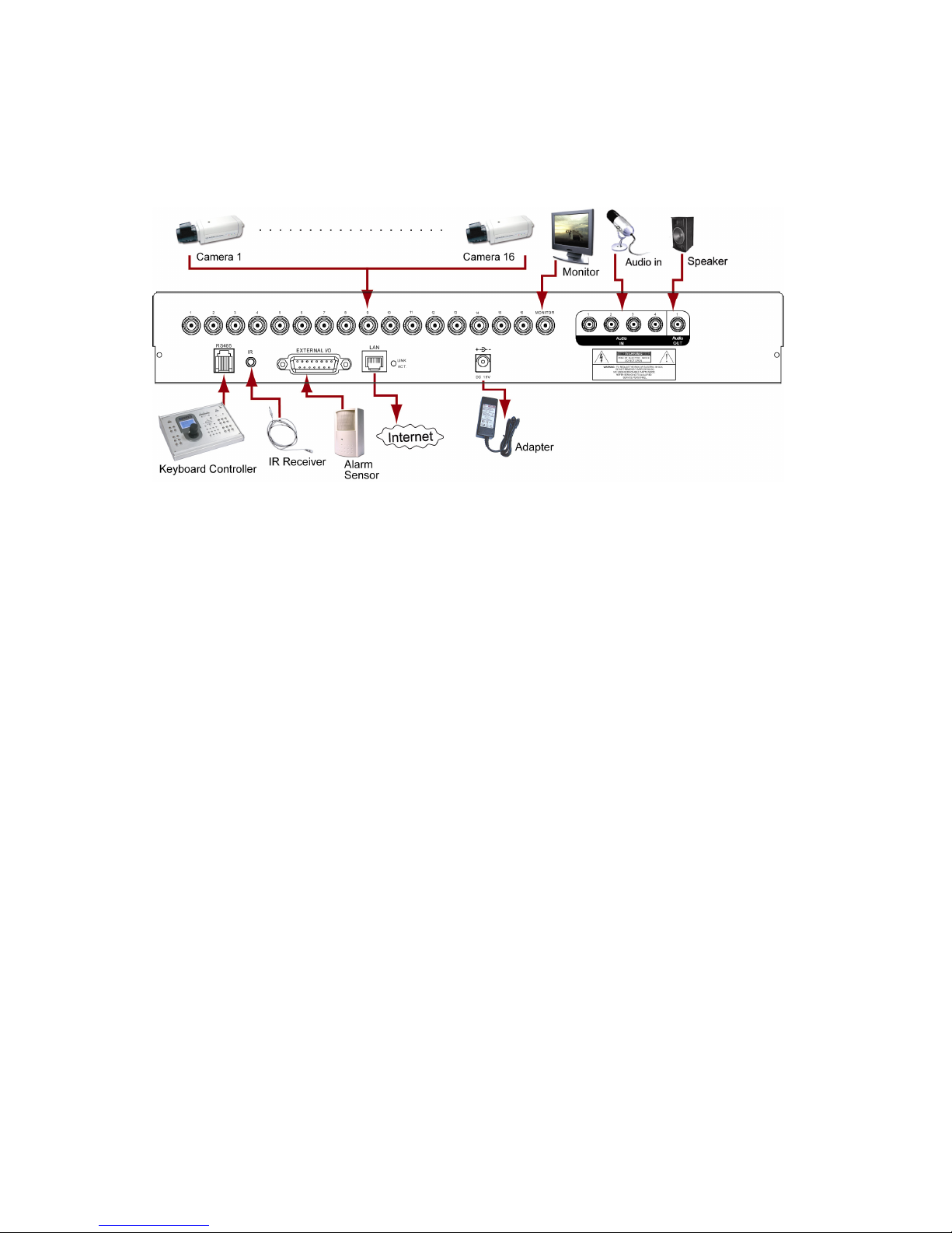
3.6 System Diagram
After you finish all the connections and setup, a surveillance system is established and you can experience the
marvelous and useful functions of this DVR. The diagram below illustrates all the available connections of this DVR for
you to picture your surveillance system.

BASIC OPERATION
-11-
' !"# $%&
4.1 Live Page
In this live page of the DVR, you can see the live viewing of 1- / 4- / 9- / 16-cut screen.
Icon
Function Icon Function Icon Function Icon
Function
Key lock Key unlock
1
st
live audio
channel
2
nd
live audio
channel
3
rd
live audio
channel
4
th
live audio
channel
Audio channel
unselected
Digital zoom mode
Digital zoom
unselected Timer recording Motion Recording
Alarm
4.2 Recording
When the recording and the pre-alarm function are activated, this device will overwrite 8GB data from the oldest
for continuous recording without notice.
1) Continuous Recording Icon
When the DVR is properly connected with camera, you can see the icon “ ” (recording) on the screen.
2) Event Recording Icon
When the motion / alarm detection is activated, once motion or external alarm happens, you will see the icon
“ ” (motion) or “ ” (external alarm) on the screen.
3) Timer Recording Icon
When the timer record is activated, you will see the icon “ ” (timer) on the screen.
(2,00%*2,
($,00%*$,
(5,00%*5,
(.,00%*.,

BASIC OPERATION
-12-
4.3 Playback
Press the “PLAY” button on the DVR control panel, and the device will playback the latest recorded video.
(428$/101/
0/195:
$;5<428$75:=/101/
1) Fast Forward () / Fast Rewind ()
You can increase the speed for fast forward and rewind on this device. In the playback mode:
Press ““ once to get 4X speed forward and press twice to get 8X speed, etc. And the maximum speed is 32X.
Press ““ once to get 4X speed rewind and press twice to get 8X speed, etc. And the maximum speed is 32X.
Note: "/1><%=00
2) Pause ( ) / Image Jog
Press “PAUSE” or “ ” button to pause the playback.
In the Pause mode:
Press “” button once to get one frame forward.
Press “” button once to get one frame rewind.
3) Stop /
Press “STOP” or “” button under playback mode, the screen of this device will return to live monitoring mode.
4) Slow Playback
Press “SLOW” button to get 1/4X speed playback and press twice to get 1/8X speed playback.
5) Audio Playback
Press “SLOW + ZOOM” buttons or “SHIFT + AUDIO” buttons to select the live or playback sound of the audio
channels.
Icon “ ” means: Live audio of the 1st audio channel / Icon “ ” means: Playback audio of the 1st audio channel
Icon “ ” means: Live audio of the 2nd audio channel / Icon “ ” means: Playback audio of the 2nd audio channel
Icon “ ” means: Live audio of the 3rd audio channel / Icon “ ” means: Playback audio of the 3rd audio channel
Icon “ ” means: Live audio of the 4th audio channel / Icon “ ” means: Playback audio of the 4th audio channel
Icon “ ” means: The audio channel is not selected.
/0110
0
2-%*34%*"+%*2%*$%*5%*.
.%*"+%*2
4.4 Key Lock and Unlock
1) Key Lock On:
Press “MENU + ENTER” buttons on the DVR control panel to lock keys.
Or set the time-out after which the key lock function is activated (Never / 10 SEC / 30 SEC / 60 SEC). Please refer
to section “7.2 System Info” at page 28.
2) Key Lock Off:
Enter the DVR password to exit “Key Lock” mode.
05?0,8

BASIC OPERATION
-13-
4.5 Upgrade
Firmware / Multilanguage OSD Upgrade
1) Use USB to upgrade firmware or OSD:
Step 1. Format the USB memory device as FAT32 format first.
Step 2. Get the upgrade files from your distributor and save the upgrade files in your USB flash device (do not
change the file name).
Step 3. In the “ ” (SYSTEM INFO) menu, move the cursor to “UPGRADE”, and press ENTER button.
Step 4. Select “YES”, and press ENTER button again to confirm upgrade.
2) Use AP software to remotely upgrade firmware or OSD:
Step 1. Save the upgrade files at your PC (do not change the file name) and then login to the AP software.
Step 2. Press “ ” (Miscellaneous Control) button to show the miscellaneous control panel. In the miscellaneous
control panel, press “ ” (Tools) button on the miscellaneous control panel to enter the AP upgrade
window.
Step 3. Enter the user name, password, IP address and port number of the DVR.
Step 4. Press “Firmware” or “Language” tab as needed, and press “Add” to select the firmware or OSD files to
upgrade.
Step 5. Press “Update Firmware” or “Update Language” button to start the upgrade.
(,?:
4.6 Search
1) Search by List
Press “LIST” button on the DVR control panel to show the list for all types of the recorded files. Choose the list
you want to view and press ENTER button to start playback.
ALARM List the information of the alarm-trigger-recorded files.
MANUAL List the information of the manual-recorded files. The DVR will save one recorded file once
any recording setting is changed
MOTION List the information of the motion-trigger-recorded files.
SYSTEM List the information of the system-recorded files. The DVR system will save one recorded
file every one hour.
TIMER List the information of the timer-recorded files.
2) Search by Time
In the “ ” (EVENT LOG) menu list, move the cursor to “QUICK SEARCH”, and press ENTER button to enter
the quick search menu. You can search any specific events by time (Year / Month / Day / Hour / Min) and directly
play the file you find.
3) Search the Record Event by Log on the AP Software
Press “ ” (Miscellaneous Control) button to show the miscellaneous control panel. In the miscellaneous control
panel, press “ ” (Log) button to enter the “Log View” page. In this log view page, you can see the list of three
different types of recording (User / Motion / Alarm) and press “Play” button to directly playback the file.

MAIN MENU
-14-
(
5.1 Menu Configuration
CHANNEL TITLE
EVENT STATUS
STATUS
IMAGE SIZE
QUALITY
RECORD IMAGE PER SECOND
RECORD TIMER
TIMER DETECTION TIMER
DATE
FORMAT
QUICK START MENU
DATE DAYLIGHT SAVING
CAMERA
DETECTION
ALERT
NETWORK
DISPLAY
ADVANCE CONFIG
RECORD
SERIAL TYPE
BAUD RATE
HOST ID
PASSWORD
RESET DEFAULT
CLEAR HDD
UPGRADE
AUTO KEYLOCK (SEC)
LANGUAGE
VIDEO FORMAT
SYSTEM CONFIG
VERSION
QUICK SEARCH
HDD INFO
EVENT LOG EVENT LOG
ADVANCED MENU
BACKUP USB BACKUP
5.2 Menu Operation Instruction
ITEM FUNCTION
QUICK START MENU: View & change the settings of the quick start menu items
MENU Enter / exit the quick start menu
Make the selection / Change the setting
Go to the upper layer or sub-layer / Make the selection
ENTER Confirm the password entering
ADVANCED MENU: In the quick start menu, move the cursor to the icon “ ” and press “” button
to enter the advanced setting menu.
ENTER Go to the sub-layer of the advanced menu
MENU Under the sub-layer of the advanced setting menu, use this button to confirm the
settings and go back to the upper layer.
NEXT Move the cursor to this item and press ENTER button to go the next page.
BACK Move the cursor to this item and press ENTER button to go the previous page.
Other operations in the advanced menu are the same as in the quick start menu.

QUICK START MENU
-15-
)*
Press MENU button and enter the password to go to the quick-start menu list. The default admin password is 0000.
Users can change the password later. Please refer to the section “7.2 System Info” at page 28.
6.1 Status
In this menu list, you can check and change some display settings.
Move the cursor to icon and you will see the following screen:
QUICK START
CHANNEL TITLE ON
EVENT STATUS ON
IMAGE SIZE CIF
QUALITY BEST
IMAGE PER SECOND 120
RECORD TIMER OFF
DETECTION TIMER OFF
DATE 2007 / AUG / 08 21 : 30 : 00
FORMAT Y / M / D
DAYLIGHT SAVING OFF
ADVANCE SELECT BACK NEXT ENTER
The submenu items are described below:
1) CHANNEL TITLE
Select to display the channel title or not (ON / OFF).
2) EVENT STATUS
Select to display the symbols of the event or not (ON / OFF).

QUICK START MENU
-16-
6.2 Manual Record
In this menu list, you can set record settings.
Move the cursor to icon and you will see the following screen:
QUICK START
CHANNEL TITLE ON
EVENT STATUS ON
IMAGE SIZE CIF
QUALITY BEST
IMAGE PER SECOND 120
RECORD TIMER OFF
DETECTION TIMER OFF
DATE 2007 / AUG / 08 21 : 30 : 00
FORMAT Y / M / D
DAYLIGHT SAVING OFF
ADVANCE SELECT BACK NEXT ENTER
The submenu items are described below:
1) IMAGE SIZE
Select one of the image sizes: FRAME, Field or CIF.
2) QUALITY
Select one of the 4 quality options: BEST, HIGH, NORMAL and BASIC.
3) IMAGE PER SECOND
Select the images per second for MANUAL RECORD. The options are as following:
NTSC IPS PAL IPS
FRAME 3, 7, 15, 30 FRAME 3, 6, 12, 25
FIELD 7, 15, 30, 60 FIELD 6, 12, 25, 50
CIF 15, 30, 60, 120
CIF 12, 25, 50, 100
Table of contents
Other CPcam DVR manuals

CPcam
CPcam CPD571 User manual

CPcam
CPcam CPC-500 User manual

CPcam
CPcam 4 CH Digital Video System User manual

CPcam
CPcam CPD500W User manual

CPcam
CPcam CPD505ZHD User manual

CPcam
CPcam 8CH MPEG-4 User manual

CPcam
CPcam CP-NVR-8CH User manual

CPcam
CPcam CPD560A User manual

CPcam
CPcam CPD537 User manual

CPcam
CPcam 8/16 CH MPEG-4 DVR User manual


Popular DVR manuals by other brands


Monacor
Monacor DMR-425A instruction manual

Honeywell
Honeywell HRDE4X4 user guide

AGI Security
AGI Security SYS-HD0460A Operation manual

e-Line Technology
e-Line Technology Sibell NVR-SB64 user manual

Sony
Sony GV-300R - Video Walkman operating instructions

VC Videocomponents
VC Videocomponents 13145 Mounting and operating manual