CPcam 4 CH Digital Video System User manual

4CHDigitalVideo System
User sManual
Pleaseread thisinstructionsthoroughlybefore operation and keep
themanual in asafeplace forfurther reference.
CPD571 V1.0
Evolution foryourDemand

All thesafetyandoperatinginstructionsshouldbereadbeforeoperation.Theimproperoperation maycause
permanentdamage.
This adaptorisonlyforthismachine.Donotuseitforotherelectronicproductsoritmaydamage
otherproducts.
Pleaseliftandplacethisequipmentgently.
Donotexposethisequipment fromdirect sunlight and keepitawayfromsourcesofintenseheat.
Donotusethisequipmentnearwaterorincontactwithwater.
Avoiddustyorhumidplace.
Donotswitchthe PowerOn&Offwithinshort period oftime(within3seconds).
Donotblock the ventilationholesatthe top and bottomoftheunit.
Donotattempt toservicethisequipmentbyyourself.
Installationshouldbemadebyqualifiedservicepersonnel.
Donot trytoretrievethe HDD databyPC.
The lightningflashwitharrowhead symbol, withinan equilateraltriangle, isintended toalert
theusertothepresenceof uninsulated"dangerousvoltage"withinthe product'senclosurethat
maybe ofsufficient magnitudetoconstituteariskof electricshocktopersons.
The exclamation point withinan equilateraltriangleisintendedtoalert theusertothepresence
ofimportant operatingandmaintenance-(servicing)instructionsinthe literatureaccompanying
theappliance.
WARNING
WARNING
1

What do youget
What do youget ?
?
FEATURES----------------------------------------------------------------------------------------
PACKAGECONTENT--------------------------------------------------------------------------
BeforeOperation
BeforeOperation
INSTALLATION GUIDE------------------------------------------------------------------------
FRONTPANEL-----------------------------------------------------------------------------------
REAR PANEL-------------------------------------------------------------------------------------
BasicOperation
BasicOperation
GETTINGSTARTED------------------------------------------------------------------------------
OPERATION----------------------------------------------------------------------------------------
Detailed Menu Setup
Detailed Menu Setup
MAIN MENU---------------------------------------------------------------------------------------
MENUOPTIONS---------------------------------------------------------------------------------
Advanced Operation
Advanced Operation
OPERATION OPTIONS------------------------------------------------------------------------
KEYLOCK----------------------------------------------------------------------------------------
RS-232 PROTOCOL----------------------------------------------------------------------------
TROUBLESHOOTING---------------------------------------------------------------------------
SPECIFICATIONS---------------------------------------------------------------------------------
APPENDIX#1 –INSTALL THEHDD----------------------------------------------------------
APPENDIX#2 –REPLACETHEHDD--------------------------------------------------------
APPENDIX#3 –PIN CONFIGURATIONS---------------------------------------------------
APPENDIX#4 –RECORDINGSPEED----------------------------------------------------------
APPENDIX#5 –NETWORK APPLICATION--------------------------------------------------
3
3
4
5
7
8
8
10
10
18
18
19
19
20
21
21
22
24
25
2
TABLEOFCONTENTS
TABLEOFCONTENTS
FEATURES
FEATURES
DVS Features
Support Manual/ Timer/ Alarm/ Motion recordingmode.
Waveletcompression format replacesTime-LapseVCR +Multiplexer/ Quad
OnScreenDisplayand RemoteControlviaVideo Server&PC
Picture-in-picture(PIP)and Picture-on-Picture(POP)functioninlive
Alarminput&outputfunction
Video lossdetected on eachchannel
Multiplexer&Quadrecording mode switching
Recordingrateup tofull size25 fields/sec.orQuad size100 IPS ( PAL ).
Support 1HDD, IDETYPE(over500GB)
Multiplequick searchbydate/time,alarm,full list
Securitypasswordprotection
RS-232, RS-485 communicationprotocol
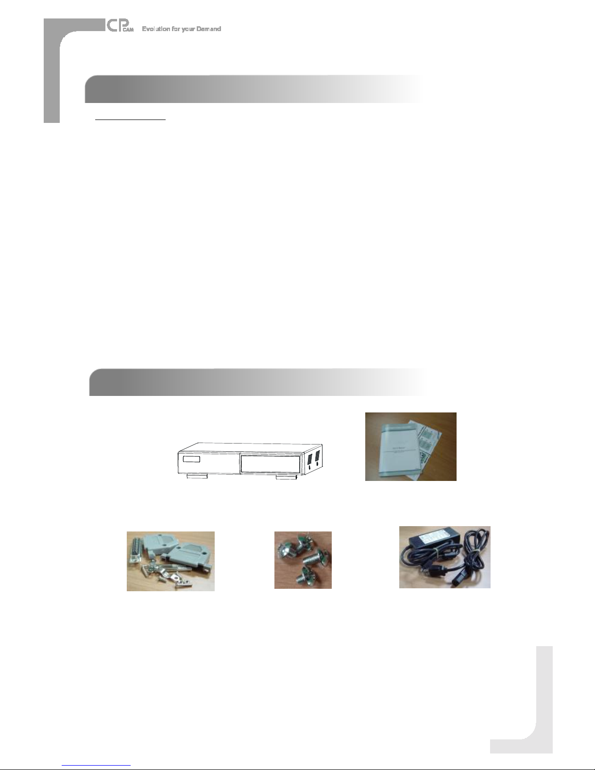
What doyouget ?
Warning:
1.Pleasecheckthepackagetomakesurethatyou receivethecompletecomponentsshownabove.
2.ThisadaptorisDC19V2A.Usercanfindtheadaptorforreplacementatacomputershopiftheadaptorisbroken.
PACKAGECONTENT
PACKAGECONTENT
User sManual
DigitalVideoSystem
3
Accessoriespack PowerAdapterandCord
Accessoriespack

1. Connectcameras and monitorto theDVS.
2. Shownbelowisanexampleof connecting theDVS to yourexisting Observation System.
3. Install HDD (ThecompatibleHDD Brandsarelistedinthefollowing table.)
Pleaserefertopage 19.Appendix #1 forinstallation instructions.
*The HDD mustbe installed beforeturningon the DVS. IfHDD isnot installed, theDVSwouldfunction asa4
CH multiplexer.
INSTALLATION GUIDE
INSTALLATION GUIDE
BeforeOperation
COMPATIBLEHARD DISK MODELS
4
Manufacturer Model Capacity Rotation
HITACHI Deskstar180GXP (120GB) 120GB 7200rpm
HITACHI Deskstar7K250, HDS722516VLAT20 160GB 7200rpm
HITACHI Deskstar7K250, HDS722525VLAT80 250GB 7200rpm
IBM Deskstar120GXP (80GB) 80GB 7200rpm
IBM Deskstar120GXP (120GB) 120GB 7200rpm
Maxtor DiamondMax536DX(60GB)4W060H4 60GB 5400rpm
Maxtor DiamondMaxPlus9 80GB 7200rpm
Maxtor DiamondMaxPlus9, Model#6Y120L 120GB 7200rpm
Maxtor DiamondMaxPlus9, Model#6Y160L0 160GB 7200rpm
Maxtor MaxLinePlus
Ⅱ
, Model#7Y250P0 250GB 7200rpm
Seagate BarracudaATAIV, ST380021A 80GB 7200rpm
Seagate BarracudaATAV, ST3120023A 120GB 7200rpm
Seagate Barracuda7200.7Plus, ST3160023A 160GB 7200rpm
WesternDigital CaviarWD1200BB-00CAA1 120GB 7200rpm
WesternDigital CaviarWD2000BB-00DWA0 200GB 7200rpm
WesternDigital CaviarSEWD2500JB 250GB 7200rpm
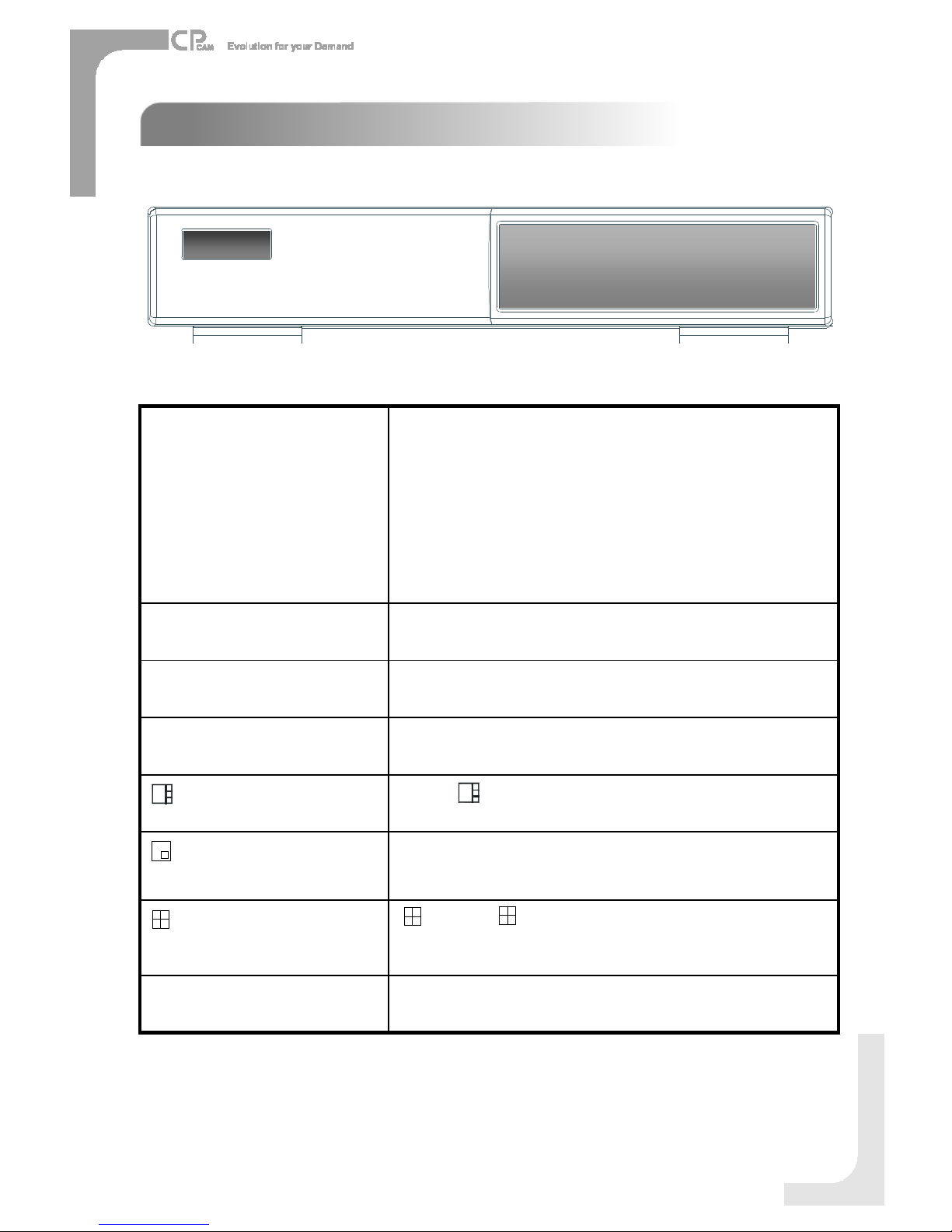
FRONTPANEL
FRONTPANEL
5
Toslowdownthe speedof playing mode.
SLOW
:Press “ ” button for4CH displaymodes
: Press “”buttoncan change the settinginthe menu.
/-4-channeldisplay mode
PIP:Press “PIP”buttonforPictureinPicturescreen.
+: Press“+ ”button canchangethesetting inthemenu.
/+ PictureinPicture
Press “ ” buttonforPictureon Picturescreen.
/ POP
Press SEARCH forsearchingrecorded video.
SEARCH
Press ENTERforconfirmation
ENTER
Press MENU toentermainmenu.
MENU
The LED Light isON underfollowing condition.
HDD : HDD is readingorrecording.
HDD Full : HDD isfull
ALARM: Toturnoff theALARMLED light.
Pleaserefertopage.13 andsettheALARMmode asOFF.
TIMER : When Timeris Enabled
PLAY: Playingmode
REC : Recording mode
LED LIGHT

6
During theLIVE orPLAYmode,pressboth “ENTER”and
“SEARCH”buttonstoswitchthe “NORMAL”or“SHARPNESS”
display.
ENTER + SEARCH
Press the CameraSelect (1-4)toselect thechannel.
CAMERA SELECT(1-4)
Press REC tostart recording.
REC
Press PLAYtoplaybackrecorded video.
PLAY
Pause: UnderDVSplaymode,itcan pausethe action.
▲:Undersetupmode, it works asUpbutton.
PAUSE / ▲
STOP:UnderDVSRecord/ Playmode, itcanstopthe
action.
▼:Undersetupmode, it works asDownbutton.
STOP/ ▼
REW: Playvideo fast backward. (Press REWbutton
againtoadjust speedas1,2, 4, 8,16,32 times)
: Undersetup mode,it works asLeft button.
REW/
FF:Playvideo fast forward. (Press FF buttonagainto
adjustspeed from1, 2,4, 8,16,32 times)
►: Undersetup mode,it works asRightbutton.
FF / ►
7
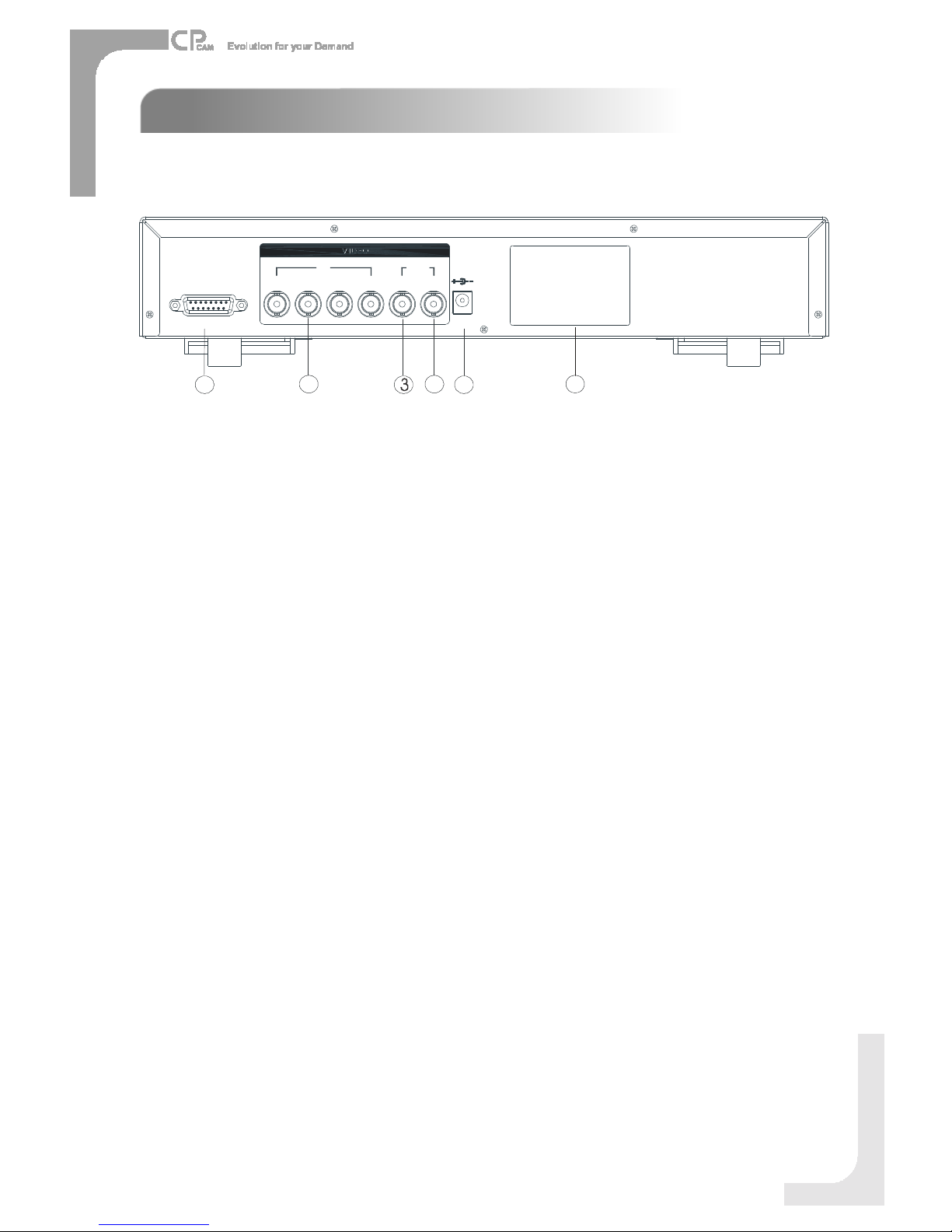
1. EXTERNALI/O
Controlled remotelybyanexternaldeviceorcontrolsystemlikeVideoWebServer.
Alarminput, externalI / Oexpansion.
2. VIDEOINPUT(1-4)
Connecttovideo source, suchascamera.
3. MAIN
ConnecttoMainmonitor.
4. CALL
ConnecttoCALL monitor. Showthe SwitchDisplay.
When alarmis triggered, thecall monitorwill showthe triggered channelaccording tothe
systemsetting.
5. POWER
Pleaseusethe provided powercord.
Warning:
1.Thisadaptorisonlyforthismachine.Donotuse itforotherelectronicproductoritmay
damageotherproducts.
2. ThisadaptorisDC19V2A.Usercanfind theadaptorforreplacementatacomputershop ifthe
adaptorisbroken.
6. FAN
Forventilation.
Note:Iftheambienttemperatureishigh orambientventilation isbad,wesuggesttoinstallafan
on therearpanel.
REAR PANEL
REAR PANEL
DC19V
EXTERNALI/O
MAIN1423
IN
CALL
OUT
12 4 5
6
1. Connect theACpowercordand plugintoanelectricaloutlet. ThePOWERLEDwill turnintoorangecolor, andother
redLEDindicatorswill turnON. It takes approximately5to15seconds toboot thesystemwiththemessage: “HDD
Detecting ”. Once successfullyconnected,thePOWERLEDwill changetogreencolor, andtheAlarmLEDwill beON.
Beforeusing the DVS, pleasehaveaHDD installedready, orit will functionas4CH multiplexer
(refertoAppendix#1forinstallationtheHDD ).
GETTING STARTED
GETTING STARTED
BasicOperation
OPERATION
OPERATION
2. Beforeoperating theDVS,setthesystemtimefirst. (refertopage.10).
NOTE:1. IftheHDD isnotinstalled correctlyornotinstalled, the “HDD notfound”messagewill
appearfor3secondsand then return to 4CHMultiplexerdisplaymode.
2. Toswitch thesystem, pull outtheACpowercord, beforeyou reconnectthepower,
press “FF”to NTSCsystemor “REW”to PAL system andthen reconnecttheACpower
cord, theDVSwill auto-detectthesystem.
8
2002 –JAN –0101:02:03
OW
(OW: HDD Overwrite)
RECORDING
TheDVSoffers3recordingmodes. Refer P.13foradvancedsettingofrecordingspeedand
resolution.Undertherecording status, ifpower isoffaccidentally, recordedvideowill still bestoredintheHDD. DVS will
returntooriginal recordingsettingafterpowerrestoresagain.
Whileyoupress “REC”button,onthescreen, youwill find thedate,time, recordingtype,the
availableHDD spaceinGBandtheletter “ ” representstherecordingmode.
(OW: HDD Overwrite)
NOTE:1. When theHDD isfull underO/WRecording mode, previousrecorded fileswill be
overwritten withoutfurtherwarning notices.
2. IftheHDD spaceisonly5GBleft,itwilldisplay “5GB”on theup-rightscreenin
orangecolor, and itwillbuzzforseconds;soas in 4GB, 3GB,2GBand1GB.IftheO/W
Recordingmode(NOTE1)ison, itwon thave thewarning buzzer.
Thereare4recordingmodes:Alarm, Motion,TimerandManualRecording.
1. ALARMRECORDING
DVRistriggeredby analarminput.symbol will beshownonthetriggeredchannel.(refer topage13)
2. MOTION TRIGGERRECORDING
Recordingistriggeredbymotiondetection. symbol will be shownonthetriggeredchannel.(refer topage14)
3. TIMERRECORDING
Recordingisscheduledby aTimer. It will indicateby thesymbol . (refertopage11)
4. MANUALRECORDING
Recordingisinitiatedmanuallyby pressingthe RECbutton.Symbol will beshown.

PLAYBACK
Press “PLAY ”button,theDVSwill showthelastrecording.
1. FASTFORWARD (F.F.)& FASTREWIND (F.R.)
You canincreasethe speedofFastForwardandRewindontheDVS.
InthePlay mode,press “►”oncetoget 2Xspeedforwardandpresstwicetoget4Xspeed,…andthemaximum
speedcanreach32X.
Press “”oncetoget1Xspeedrewindandpress twicetoget 2Xspeed, …andthemaximumspeedcanreach
32X.
2. SLOW FORWARD (S.F.)& SLOWREWIND (S.R.)
You canalsoslowdownthespeedof ForwardandRewindontheDVS.
InthePlay mode,press theSLOWbuttonandyouwill enterSlowmode.
Press “SLOW ”oncetoget1/2Xspeed forwardandpress “►”toget1/4Xspeed,…andthe slowestspeedcan
reach1/32X.
Press “”oncetoget1/2Xspeedrewindandpresstwicetoget 1/4Xspeed, …andtheslowestspeedcanreach
1/32X.
3. PAUSE
You canpausetheplaybackandtheimagewill bedisplayedonthescreen.
4. STOP
Press “STOP ”buttonunderanycircumstance, DVSwill returntolivemonitoringmode.
5. IMAGEJOG DIAL
It will allowyoutomanuallyviewvideoframe-by-frame,oneimageatatime.
WhileinPLAY mode,press “PAUSE ”, itwill pausethescreen.
Press “►”buttonadvancesthefrozenscreenoneimageforward.
Press “”buttonmoves back oneimage.
6. SHARPNESS
DuringtheLIVE orPLAY mode,press both “ENTER”and“SEARCH”buttonstoswitchthe “NORMAL”or
“SHARPNESS”display.
CAMERASELECT(1-4)
PressCameraSelect(1-4)toselectthecameratodisplayinfull screen.
9

10
Thereare11options availableintheMainMenu:
TIMER ----------ProgramTimer Recording
CAMERA -------CameraSetup
RECORD -------RecordingMode Setup
ALARM ---------AlarmSetup
DWELL ---------Dwell timeSetup
PIP ---------------PictureinPictureSetup
MOTION --------MotionDetectionSetup
DISPLAY -------Display ModeSetup
REMOTE -------RemoteControlSetup
USER -----------UserPasswordSetup
SYSTEM -------SystemSetup
EVENT ---------EventList
Outlinedbelowarethebuttons usedfor Menusetting:
▲”and ▼”:Scrollupanddownwithinamenuoption
”and ►”:Scroll sideways withinamenuoptionthathasbeenselected
+ ”and -”:Increaseanddecreasethenumberorchange valueswhenanoptionisselectedandisblinking
ENTER: Selectasubmenu/anoptionunderasubmenuforbrowsing/ modification
MENU : Completemodificationofamenuoption;exit amenu
MAIN MENU
MAIN MENU
(MENU)
TIMER
CAMERA
RECORD
ALARM
DWELL
PIP
MOTION
DISPLAY
REMOTE
USER
SYSTEM
EVENT
DetailedMenuSetup
(MENU)
TIMER
CAMERA
RECORD
ALARM
DWELL
PIP
MOTION
DISPLAY
REMOTE
USER
SYSTEM
EVENT
MENU OPTIONS
MENU OPTIONS
SYSTEM
4. KEY MUTE
TosettheKEYMUTE. Whenthesettingis “YES”, therewill be nosoundwhenyoupressanykey.
5. HDD OVERWRITE
Toset theHDD OVERWRITE. WhentheHDD isfull under O/Wrecordingmode,previouslyrecorded
fileswill beoverwrittenwithoutfurther warningnoticeswhentheHDD OVERWRITE isON.
1. BUZZER
Set theBUZZ “ON”, it will buzzby eventoccurrence.
2. EXTALARM
TosettheEXTALARM. Itwill betriggedby eventoccurrencewhenthesettingisON.
3. VLOSS ALARM
TosettheVLOSSALARM. Whenthesettingis “ON”, the alarmwill start bythesetting
ofBuzzer,EXTalarmorAlarmDuration.

11
(SYSTEM)
BUZZER ON
EXTALARMON
VLOSS ALARMON
KEYMUTEYES
HDD OVERWRITEYES
MESSAGELATCH YES
DATEDISPLAYD/M/Y
DATE26-DEC-2003 [FRI]
TIME22:55:34
CLEAR HDD YES
SYSTEMRESETYES
6. MESSAGELATCH
Toselect whether theDVS messages will disappearafter 10
secondsor remainonscreen. NO isthedefault setting whichthe
messages will disappearafter10sec.
NOTE: Videoloss,and Alarmmessages will beshown
the sameasAlarmDurationtime.
7. DATEDISPLAY
Toset thedateY/M/D, M/D/Y,D/M/YandOFFonmonitorornot.
8. DATE
Toset thedateontheDVS.
9. TIME
Toset thetimeontheDVS.
10. CLEAR HDD
Deleteall thecontentsoftheHDD. Whenyouchoose “YES”onthisoption,press “ENTER”andyou
will bepromptedwiththequestionshown:Press “”toclear HDD orpress ”←”tocancel.
11. SYSTEMRESET
Resetallsystemtothefactorydefault settings.Select “YES”andpress “ENTER”button.
TIMER
1. DAY
Selecttheday,ordays ofthe week(Mon–Fri/ Sat-Sun/ Daily) thatyou wishtoschedule
theDVStoautomaticallyrecord.
NOTE:
1.Change thedateby “+”and “-”buttons.
2.Ifyouhaveselectedthedateand Timer recording setfromthatspecificday
toanewday, thenthe Timer RecordingSchedule will be set aswhole week.
Forspecificdateof Timer RecordingSchedule,itisnot recommendedtoset
EndingTimeover23:59.Forexample: If you set TimerScheduleDayasSunday,
andSTARTfrom11:30,but End on00:20, thenRecordingTimerScheduleis
setasfromeverySunday's 11:30tonext Sunday‘s00:20. If youonlywant toset
RecordingTimerSchedulefromeverySunday11:30toMonday00:20, thenyou
should set RecordingTimerScheduleasSundayfrom11:30 to23:59, and Monday
from00:00 to00:20.
3.It isnotsuggested that userspress “STOP”button orrestartthesystemduring setting
time.Indoingso,therecordingwill stop,anduserscan resumerecordingbypressing
“ENTER”+ “REC”.
(MENU)
TIMER
CAMERA
RECORD
ALARM
DWELL
PIP
MOTION
DISPLAY
REMOTE
USER
SYSTEM
EVENT
2. START
Set thetimetostarttherecording.
3. END
Set thetimetoendtherecording.
4. IPS (IMAGES PER SECOND)
NTSC 30、15、8、4、2、1
PAL 25、12、6、3、2、1
5. QUALITY
Select thequalityofrecordingimage: BEST, HIGH, NORMandBASE.
6. MODE
Therearethreerecordingmodesettings :
QUAD-FRAME, QUAD-FIELD, MULTIPLEX.
NOTE:Toensurethebestrecordingquality,wedon’tsuggest
theusersswitchadifferentrecordingmodeduring
theperiodofrecording.
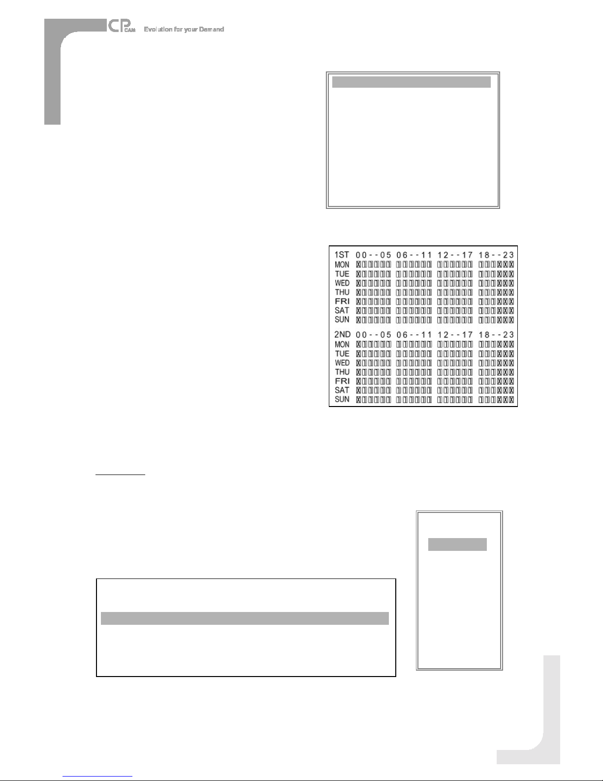
7. TIMER ENABLE
WhenTIMERENABLEis “YES”, press “menu”button,you
cansee thetimerdiagramaccordingtoyoursetting.
(TIMER)
DAY STARTEND IPSQLTMODE
DAILY01:0022:0030BESTQ-FR
OFF 00:0000:0030BESTQ-FI
OFF 00:0000:0030BESTQ-FI
OFF 00:0000:0030BESTQ-FR
OFF 00:0000:0030BESTQ-FR
OFF 00:0000:0030BESTQ-FR
OFF 00:0000:0030BESTMUX
OFF 00:0000:0030BESTQ-FI
TIMERENABLE: YES
12
CAMERA
1. TITLE
Assignatitletoeachcamera.Initiallyeachtitleisthecamera snumber.
(Max:8characters)
2. ALARM
SelectLOW/ OFF / HIGH foralarmpolarity.ThedefaultvalueisLOW.
(MENU)
TIMER
CAMERA
RECORD
ALARM
DWELL
PIP
MOTION
DISPLAY
REMOTE
USER
SYSTEM
EVENT
TITLE
18
151518
ON
HIGH
CAMERA04
18
1515
18OFF
HIGH
CAMERA03
18
15
15
18
OFF
OFF
CAMERA02
181515
18
ON
LOW
CAMERA01
HUE
CLCT
BR
RECALARM
(CAMERA)

(RECORD)
RECORD IPS 30
QUALITYNORMAL
RECORD MODEQUAD-FRAME
13
3. REC(RECORD)
Setupwhichchannelyouwant torecord.
ON : whenalarminput istriggered, DVSwill recordalarmingchannel morefrequently.
Forexample: whenCH01istriggered, therecordmethodwill become1-2-1-3-1-4….
OFF : DVSwill not record.
4. BR (BRIGHTNESS)
Adjust thebrightness ofeachchannel.Thelevel isfrom0to63.
5. CT(CONTRAST)
Adjust thecontrastofeachchannel. Thelevelisfrom0to63.
6. CL(COLOR)
Adjust thecolorofeachchannel. Thelevel isfrom0to63.
7. HUE (HUE)
Adjust thehueofeachchannel.Thelevel isfrom0to63. (MENU)
TIMER
CAMERA
RECORD
ALARM
DWELL
PIP
MOTION
DISPLAY
REMOTE
USER
SYSTEM
EVENT
RECORD
1. RECORD IPS
Select therecordingspeed.Theoptions are
asfollowing:
NTSC 30、15、8、4、2、1
PAL 25、12、6、3、2、1
2. QUALITY
Therearefourqualitysettings:BEST,HIGH, NORMAL, BASIC.
NOTE:TherelationshipofRecordtime,IPS andRecordquality,
pleaserefertopage.24 RecordingSpeed.
3. RECORD MODE
Therearethreerecordingsettings:QUAD-FRAME, QUAD-FIELD,
MULTIPLEX.
ALARM
1. ALARMENABLE
Alarmwill betriggeredbyeventoccurrencewhenthesettingis “YES”.
2. ALARMDURATION
Set thereaction timeofthe alarmmoderesponds toabuzzer.
Default settingis10Sec. Options are10Sec,15Sec, 20Sec,
30Sec,1MIN,2MIN,3MIN, 5MIN, 10MIN,15MIN,30MIN,
ALWAYS,AUTO.
NOTE:1.Videoloss, andAlarm messageswillbeshownthesameasAlarm Durationtime.
2. WhenthesettingisAUTO,thealarm durationtimeisaccordingtothesetting
oftheexternalalarm device.
3.DuringALARMDURATION’Ssettingtime,userscanrestartALARMfunctionby
pressingboth ENTER”+ STOP”buttons.
(MENU)
TIMER
CAMERA
RECORD
ALARM
DWELL
PIP
MOTION
DISPLAY
REMOTE
USER
SYSTEM
EVENT

3. REC IPS
Select theimagespersecondof recordingduringanALARM.
Theoptionsareasfollowing:
NTSC 30、15、8、4、2、1
PAL 25、12、6、3、2、1
4. QUALITY
Therearefour recordingqualitysettingsduringanALARM:
BASIC, BEST, HIGH, NORMAL.
5. RECORD MODE
Therearethreerecordingsettings:QUAD-FRAME, QUAD-FIELD,
MULTIPLEX.
(ALARM)
ALARMENABLEYES
ALARMDURATION 15MIN
RECORD IPS 30
QUALITYNORMAL
RECORD MODEQUAD-FRAME
DWELL
1. NORM
TosetuptheDWELLtimeperiodthateachchannel autosequentially
showsoncall monitor.Thelevel isfrom1to15Secor OFF.
2. ALARM
TosetuptheDWELLtimeperiodwhen alarminput istriggered.
Thelevel isfrom1to15Secor OFF.
PIP
1. FULLSCREEN
Tosetupthefull screenbackgroundpicturedisplay.
2. PIPSCREEN
Tosetupthepicturewitha1/9sizescreen “insert”.
3. POSITION
Therearesixpositionsettings : D/L, D/M, D/R,U/L,U/M, U/R.
(MENU)
TIMER
CAMERA
RECORD
ALARM
DWELL
PIP
MOTION
DISPLAY
REMOTE
USER
SYSTEM
EVENT
(PIP)
FULL SCREEN CAM1
PIPSCREEN CAM2
POSITION D/R
14
(MENU)
TIMER
CAMERA
RECORD
ALARM
DWELL
PIP
DISPLAY
REMOTE
USER
SYSTEM
EVENT
(DWELL)
NORMALARM
CAM101 01
CAM201 01
CAM301 01
CAM401 01
MOTION
1. SEN (SENSITIVITY)
Setsthesensitivityofthepixel-basedMotionDetectionfeaturefrom1to99.
Thehighest sensitivitysettingis01, thelowestsensitivitysettingis99.
Thedefault settingis70.
2. MD-NUM(MOTIONDETECTION NUMBER)
Setsthenumberof targetsinwhichMotionmustoccur inorder totriggeranAlarm
(from1-99target areas).
Note:MD-NUMcannotbe lessthanthe numberoftargetsset inthe AREA.
3. RE(REFERENCE)
Set theReferenceimagetowhichthecurrent screeniscompared(from1-99).
Forexample, thevalue64wouldcomparethecurrent image tothe64th previous
screenimage.Thehigher valuemay increase thesensitivity.
4. DET(DETECTION)
Themotion detectiononeachchannelcanbeturnedto
ON or OFFindividually.
(MENU)
TIMER
CAMERA
RECORD
ALARM
DWELL
PIP
MOTION
DISPLAY
REMOTE
USER
SYSTEM
EVENT
15
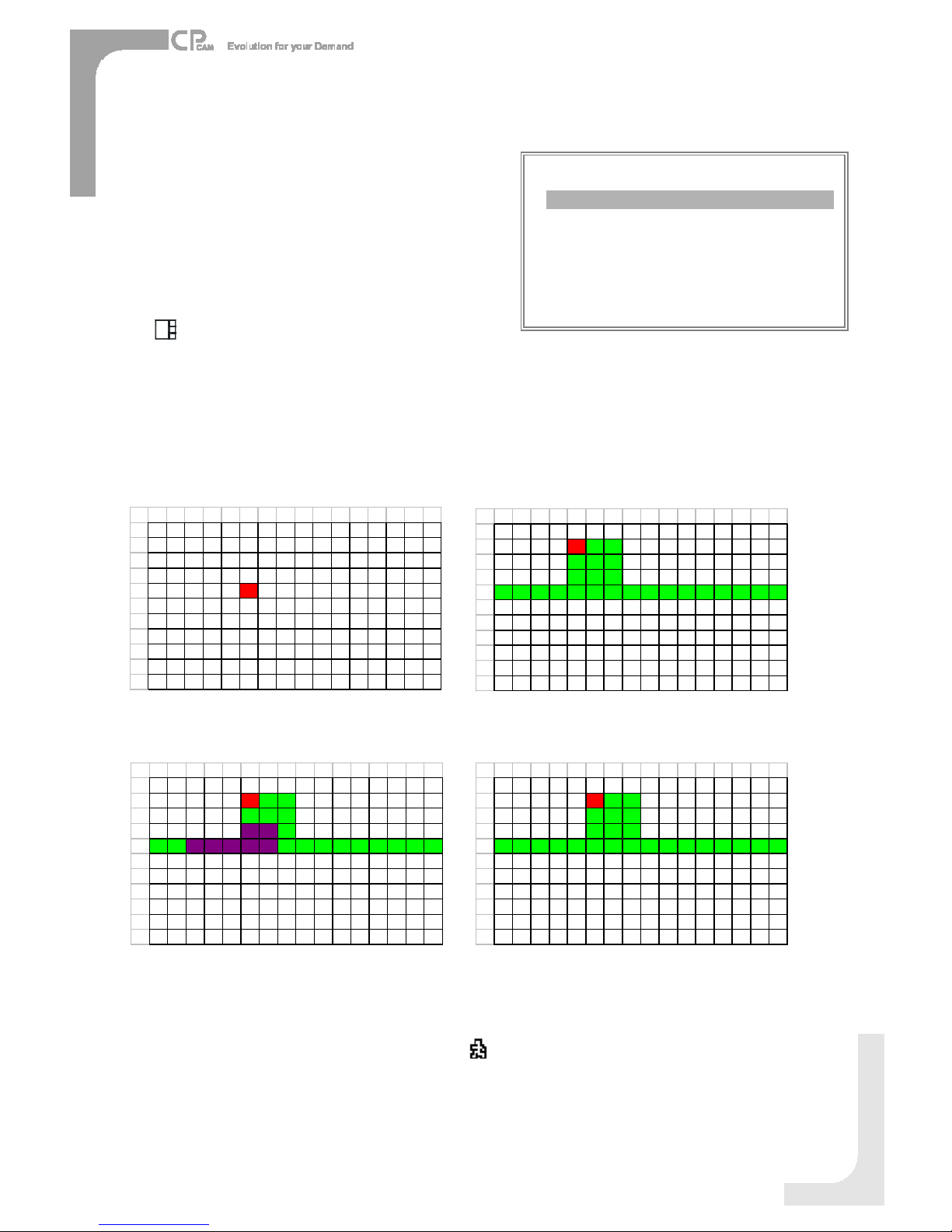
Figure1-2
MOTIONDETECTIONSETTING —ROWSETUP
Figure1-1
MOTIONDETECTIONSETUP
12345678910 11 12 13 14 15 16
1
2
3
4
5
6
7
8
9
11
12
12 3 4 5 6 7 8 9 10 11 12 13 14 15 16
1
2
3
4
5
6
7
8
9
11
12
Figure1-3
MOTIONDETECTIONTRIGGERED-TURN INTOPURPLE
Figure1-4
BACKTO MOTIONDETECTIONSETTING
1
2345678910 11 12 13 14 15 16
1
2
3
4
5
6
7
8
9
11
12
1
2345678910 11 12 13 14 15 16
1
2
3
4
5
6
7
8
9
11
12
6. MOTION RECORD
WhentheDETsettingis “ON”, youcanset uptheMOTION RECORD function,
1.Select “ON”tosetupthemotiontriggerrecording: It canautomaticallyswitchtoRecordMode. Themotion
detectionwill changethescanningsequenceandshowonthemonitor.
5. AREA
Press theENTERbuttononthisoptiontosetthePixel-based
MotionDetectionAreaforeachchannel. Redtargetsrepresent
wherethe target is(Figure1-1). Greentargetsrepresentthe
MotionDetectionArea(Figure1-2),andPurpletargetsrepresent
motioncurrentlytakingplace(Figure1-3).Afterstopdetecting,
thecoloroftargetwill begreen(Figure1-4).
TomodifytheMotionDetectionArea,usethefollowingcontrols:
:turntheselectedtargetON/OFF.
▲▼ ►: navigatesbetween targets
: turnsall targetson the screen ON/OFF
+: turnall targetsintheselectedrowON/OFF
Note:Whenthe DET”(DETECTION)settingis ON”,youmustsetthemotiondetectionAREAoritwon’tbetriggered.
(MOTION)
SENMD-NUMREDET
CAM17003 64ONAREA
CAM27003 64OFF AREA
CAM37003 64ONAREA
CAM47003 64ONAREA
MOTIONRECORD :ON
DAYSTARTEND
DAILY00: 0000: 00

16
(MENU)
TIMER
CAMERA
RECORD
ALARM
DWELL
PIP
MOTION
DISPLAY
REMOTE
USER
SYSTEM
EVENT
REMOTE
1. REMOTEMODE
Set theremotemodefor connectionwithcomputerviaRS-232 or RS-485.
(Pleaserefertopage.19for RS-232&RS-485RemoteProtocol).
2. BAUD RATE
Set theremoteprotocoltransmittingbaudrate. Availableoptions are115200,
57600,19200,9600,4800,3600,2400,1200.
3. ID
TocontroldifferentDVS by setting
remoteprotocol. IDnumber canbe set
from000to255.
(REMOTE)
REMOTEMODERS-485
BAUD RATE9600
ID 255
(DISPLAY)
TITLEDISPLAYYES
OSD COLOR YELLOW
LOSS SCREEN GREEN
TIMEPOSITION NORMAL
(MENU)
TIMER
CAMERA
RECORD
ALARM
DWELL
PIP
MOTION
DISPLAY
REMOTE
USER
SYSTEM
EVENT
DISPLAY
1. TITLEDISPLAY
Tosetthetitleshownon monitorornot.
2. OSD COLOR
Select theOSD(OnScreenDisplay) color. Theoptionsare
YELLOW, GREEN, CYAN, BLUE,PINK, GRAY,WHITE,RED.
3. LOSS SCREEN
Retainthelastpictureor selecttheLOSS SCREENcolor.
TheoptionsareGREEN, BLACK,BLUEandRETAIN.
4. TIMEPOSITION
TosettheOSDPOSITION shownonmonitor.
Theoptions areNORMALorCENTER.
NOTE: The triggerrecording timewilldepend on ALARMDURATIONmode setting (Pleaserefertopage.13forALARMDURATION)and it will
recordfromthe last triggertime. Forexample,when the alarm durationsetting is1min, the recording timeisfrom9:00:00 to9:01:00. If the
motion detection triggedagainat 9:00:40, thetrigged recording timewill from9:00:00 to9:00:40and9:00:40to9:01:40. The total
recording timeis00:01:40.
2.Select ”OFF”: Thescreenstill showsandifit isinrecordmode, themotiondetectionwill changethescanning
sequence.
7. DAY/ START/ END
TosetuptheDAY andtheSTART/END timefor motiontriggerrecordingtimer setting.
Forexample :If the motion isdetectedonCamera#1,itsrecording &scanning sequencewill bemorefrequently.The sequence
will beas1st,2nd, 1st, 3rd,1st, …4th. And channel1willshowonthescreen.If 2ndcameraand 3rdcamera
bothmotion detectionareactivated, theywill be scanningas2nd,3rd,1st, 2nd,3rd, 4th,2nd, 3rd,1st, 2nd,3rd,
4th …and viceversa.AndCH2&CH3will showforaperiod oftimewhichissameasAlarmDurationtime.

(MENU)
TIMER
CAMERA
RECORD
ALARM
DWELL
PIP
MOTION
DISPLAY
REMOTE
USER
SYSTEM
EVENT
USER
1. USER
Tosetuptheuser accountfor controlling. It
allows8userssetting.
Supervisor –Controlall thefunctions.
OtherUsers –Viewall functionsexcept the
menusetting.
2. PASSWORD
Tosetthesecuritypasswordforeachaccount.
Themaximumlengthof user spasswordis4
characters.
NOTE:ToswitchtodifferentUSER,press
ENTER”+ MENU”buttonsto KEY
LOCK”andthenenterthedifferentuser’s
passwordtoUNLOCK.
(USER)
PASSWORD
SUPERVISOR0000
USER10000
USER20000
USER30000
USER40000
USER50000
USER60000
USER70000
17
(MENU)
TIMER
CAMERA
RECORD
ALARM
DWELL
PIP
MOTION
DISPLAY
REMOTE
USER
SYSTEM
EVENT
EVENT
C1VLOSS 26-DEC-2002 03:00:00
C2ALARM26-DEC-200203:00:00
KUNLOCKS26-DEC-2002 03:00:00
M-HD ERR 26-DEC-200203:00:00
M-HD WARM26-DEC-2002 03:00:00
PWR REST26-DEC-2002 03:00:00
DMAERROR 26-DEC-2002 03:00:00
M-HD REPL26-DEC-2002 03:00:00
↑+↓: CLEAR
Asinglepagecandisplay 16recordedevents.Press “”or “►”tochangethe
pages orpress “▲”+ “▼”toCLEARtheEVENTrecord.
DISK FULL: HDD isfull
PWRREST :Powerrestored
M-HD REMS: HDD removal
M-HD REPL: HDD replace
M-HD ERR : HDD error
M-HD WARM: HDD warning
KUNLOCKS:Keyisunlock
DMAERROR: DMAerror(Direct MemoryAccess)
C1VLOSS :Videoloss onCh1
C2ALARM: Channel2hasbeentriggeredbyexternalI/Oalarm
SYSTEMERROR: Systemfail
POWERRESTORE: Power restored

18
VIDEO LOSS
Screenwill display “VLOSS”inthecenterofdisplaypicture, if the videoinput isnotconnectedproperly.
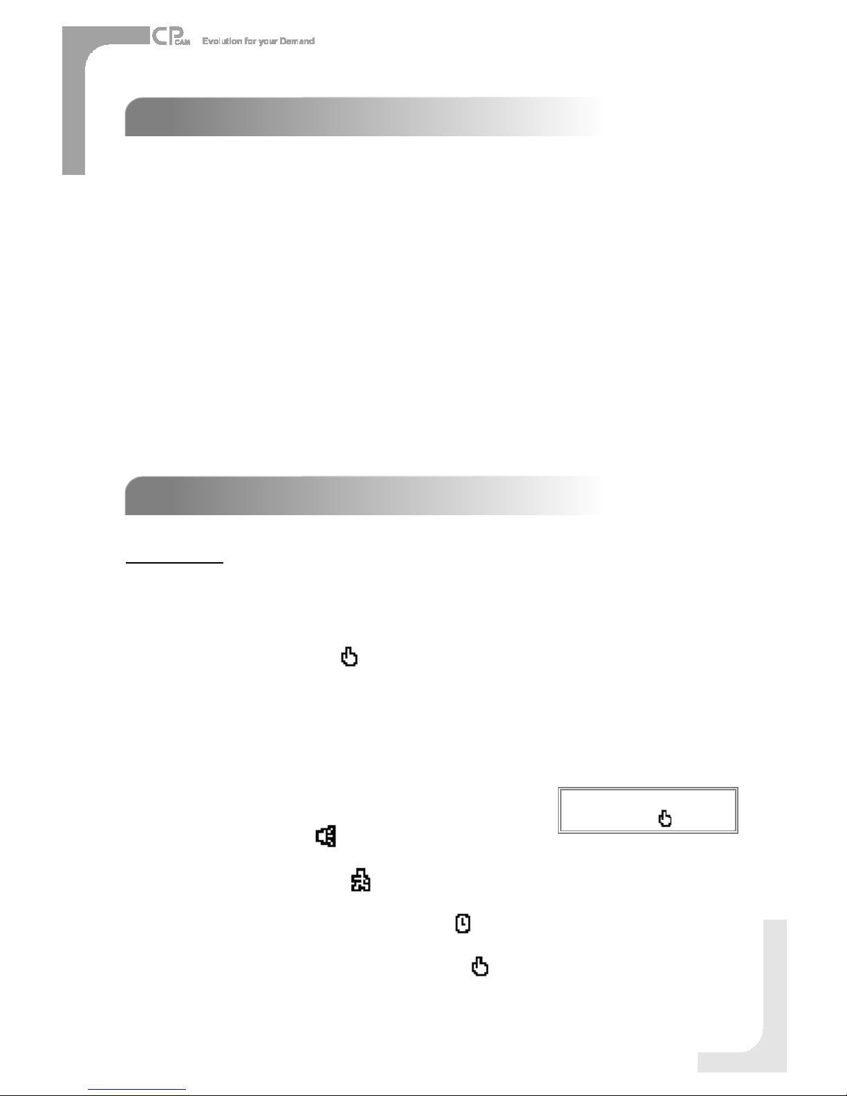
SEARCH
1. LASTRECORD
Playthelast recordedpieceofvideo.
2. FULLLIST
Listall recorded videoontheHDD whichsortedby time.
3. ALARMLIST
Listall recorded videotriggeredbyAlarm.
NOTE: If therearenoAlarminthe record,thescreenwill
display “EMPTY”.
4. MOTION LIST
Listall motiontriggeredrecords.
5. TIMESEARCH
Findvideorecordedonaspecificdatethatisentered.
OPERATION OPTIONS
OPERATION OPTIONS
2003-JAN-01 01:02:03M
2003-JAN-05 05:02:03M
2003-MAR-12 04:02:03M
2003-APR-02 03:02:04 M
2003-MAY-01 05:02:03M
2003-AUG-09 01:02:01M
: PAGEUP→: PAGEDOWN
: ManualRecording
:AlarmRecording
:Timer Recording
M: StorageinMaster HDD
S: StorageinSlaveHDD
NOTE: It will displaydifferentcoloroneach recordlist
mentionabove.
AdvancedOperation
KEYLOCK
KEYLOCK
Foradvancedsecurity, youcan “Lock”thebuttonsonyour DVS.Key-Lock preventsotherpeoplefromusingthesystem.
PressENTERandMENU atthe sametimetoenableKey Lock.
PressENTERandMENU atthe sametimeand keyinpassword(Default :0000), thenpress “ENTER“todisableKey Lock.
NOTE:ToswitchtodifferentUSER,press ENTER”+ MENU”buttonsto KEY LOCK”andthenenterthedifferentuser’s
passwordtoUNLOCK.
LASTRECORD
FULL LIST
ALARMLIST
MOTION LIST
TIMESEARCH

19
RS
RS-
-232 REMOTEPROTOCOL
232 REMOTEPROTOCOL
Youcanuse thePCkeyboardtosimulateDVSkeypad.
DATA: REMOTEPROTOCOLusing8bitdata、1start bit、1stopbit
FUNCTIONCODEASCIIFUNCTIONCODEASCII
KEY_MENU 0x4D M KEY_PLAY 0x50 P
KEY_SEARCH 0x73 s KEY_DOWN 0x4E N
KEY_ENTER 0x0D ENTER KEY_RIGHT 0x52 R
KEY_QUAD 0x51 Q KEY_KEY_LOCK 0x4B K
KEY_POP 0x5A Z KEY_CH1 0x31 1
KEY_PIP 0x70 p KEY_CH2 0x32 2
KEY_SLOW 0x53 S KEY_CH3 0x33 3
KEY_REC 0x72 r KEY_CH4 0x34 4
KEY_LEFT 0x4C L TIMERRECPROCEED 0X54 T
KEY_UP 0x55 U
TROUBLESHOOTING
TROUBLESHOOTING
Whenmalfunctionoccurs, itmay notbeserious andcanbecorrectedeasily.Thefollowingtabledescribesthemost
common problemswiththeirsolutions.Pleasereadthoroughlybeforecallingyour DVSdealer.
PROBLEM SOLUTION
lCheck powercordconnections.
lConfirmthat thereispowerat the outlet.
lCheck ifit isunderKeyLock mode.
lPress "MENU" &"ENTER" toexist KeyLock mode.
Norecorded video lCheck ifthe HDD isinstalled properly.
TimerRecordenabledoesnot
working
lCheck ifthe TimeEnableisset toYES
lCheck cameravideo cableand connections.
lCheck monitorvideo cableand connections.
lConfirmthat the camerahaspower.
lCheck cameralenssetting.
Nolivevideo
Nopower
Not working when press any
button
Toswitchthe system, press “FF”toNTSCsystemand
“REW”toPALsystem. (RefertoPage 8"Getting Started").
NTSC&PALSystemswitch
Table of contents
Other CPcam DVR manuals

CPcam
CPcam CPD537 User manual

CPcam
CPcam CPD500W User manual

CPcam
CPcam CPD505ZHD User manual

CPcam
CPcam CP-NVR-8CH User manual

CPcam
CPcam CPD548D User manual

CPcam
CPcam 262Z User manual

CPcam
CPcam CPD541D User manual

CPcam
CPcam CPD541 User manual

CPcam
CPcam 8CH MPEG-4 User manual

CPcam
CPcam 8/16 CH MPEG-4 DVR User manual


