CPcam CPC-500 User manual

500AW V1.0
Inteligent
Inteligentní
ní & Triplex
& Triplexní
ní
4
4-
-kanálový
kanálový MPEG
MPEG-
-2
2
digitální záznam
digitální záznam
CPC500W V1.2
DOVOZCE a DISTRIBUTOR do eské Republiky
DOVOZCE a DISTRIBUTOR do eské Republiky
VIAKOM s.r.o.,
VIAKOM s.r.o., Slovenská 891/5, 120 00 Praha 2
Slovenská 891/5, 120 00 Praha 2
www.viakom.cz
www.viakom.cz
Uživatelský manuál
Uživatelský manuál -
-ENG
ENG

This adaptor is only for this machine.
Do not use it for other electronic products or it will damage other products.
Please lift and place this equipment gently.
Do not expose this equipment to direct sunlight.
Do not use this equipment near water or in contact with water.
Do not spill liquid of any kind on the equipment.
Please power down the unit before unplugging.
Do not block the ventilation holes at the top and bottom of the unit.
Do not switch the Power On & Off within short period of time
(within 3 seconds).
Installation should be made by qualified service personnel.
All the safety and operating instructions should be read before operation.
The improper operation may cause permanent damage.
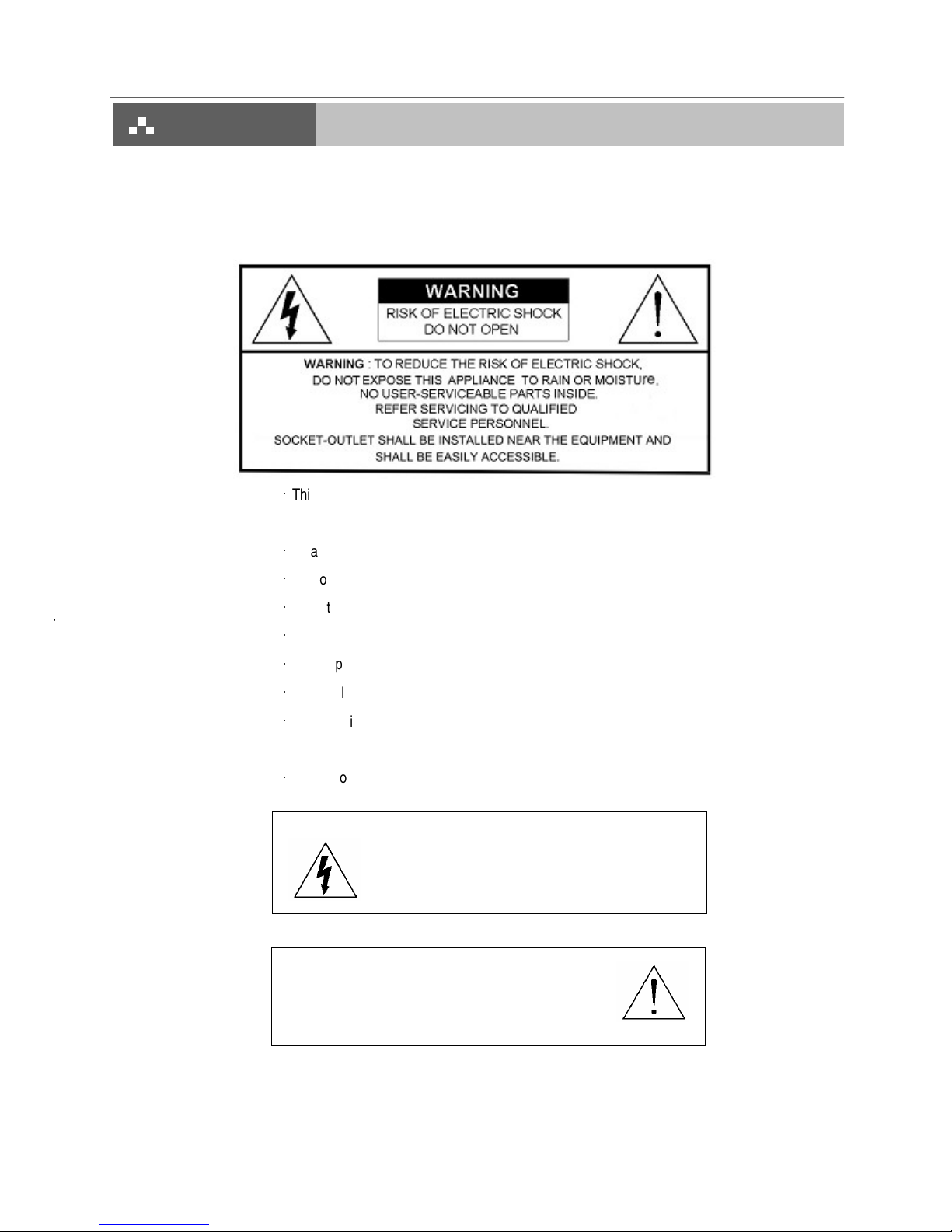
The lightning flash with arrowhead symbol, within an
equilateral triangle, is intended to alert the user to the
presence of uninsulated "dangerous voltage" within the
product's enclosure that may be of sufficient magnitude to
constitute a risk of electric shock to persons.
The exclamation point within an equilateral triangle is
intended to alert the user to the presence of important
operating and maintenance-(servicing) instructions in the
literature accompanying the appliance.

1. What do you get ?
FEATURES
PACKAGE CONTENT
SPECIFICATIONS
2. Before Operation
INSTALLATION GUIDE
FRONT PANEL
REAR PANEL
3. Basic Operation
GETTING STARTED
OPERATION
RECORDING FUNCTION
PLAYBACK FUNCTION
4. Detailed Menu Setup
MAIN MENU
MENU OPTIONS
RECORD SETTING
TIMER SETUP
CAMERA SETTING
DETECTION SETTING
DISPLAY SETTING
PIP SETUP
DWELL SETUP
USER SETTING
SYSTEM SETTING
BUZZER SETUP
UPGRADE SETUP
EVENT SETTING
NETWORK
PTZ
RETR
5. Advanced Operation
OPERATION OPTIONS
2X ZOOM
VIDEO LOSS
SEARCH MODE
USB BACKUP
KEY LOCK
6. Network setting guide
HARDWARE CONNECTION AT SERVER SIDE
SOFTWARD INSTALLATION
LOCAL SETTING
STATIC IP SETTING
DYNAMIC IP SETTING
SOFTWARE OPERATION AT CLIENT SIDE
INTRODUCTION OF BASIC OPERATION
PLAYBACK OPERATION
ADVANCED SETTING
CONNECT VIDEO WEB SERVER VIA IE BROWSER
7. F & Q
TROUBLESHOOTING
8. APPENDIX
APPENDIX A – INSTALL THE HDD
APPENDIX B – REPLACE THE HDD
APPENDIX C –RECORDING SPEED
APPENDIX D – PIN CONFIGURATIONS
1
1
2
3
4
5
6
7
7
7
9
10
10
11
12
13
15
16
17
17
18
19
19
20
20
21
21
22
22
22
23
24
25
26
27
28
30
31
39
39
40
41
44
45
46
47
47
48
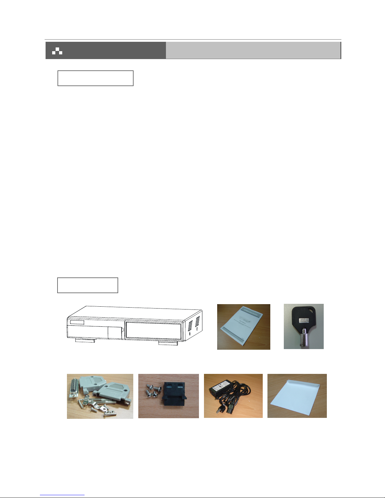
Warning:
1. Please check the package to make sure that you receive the complete accessories shown above.
2. The adaptor is DC19V 2A. If it is damaged, users can find replacement adaptor locally with this specification.
Accessories pack Power Adapter and Cord
Accessories pack
2 Keys
User’s Manual
Digital Video Recorder(with HDD cartridge)
CD-ROM
1
•
R.E.T.R (Remote Event Trigger Recording)
•
Remote control via the internet
• Control PTZ camera
• MPEG-2 compression format
• Triplex function (record, playback and live at the same time)
• USB Backup ( backup files by USB Sticker and USB HDD devices)
• More accurate motion detection function
• Connect video web server via IE browser
• Auto sending message by e-mail or FTP when alarm occurs
• High resolution: 720 X 480 pixels <NTSC> 720 x 576 pixels <PAL>
• Picture-in-Picture (PIP) in live
• Alarm input & output function
• Linear Zoom (2x)
• Recording rate: Up to 30 frames/sec (NTSC) ; Up to 25 frames/sec (PAL)
• Support 1 removable HDD, IDE TYPE.
• Quick multiple search by event / time list
• Security password protection

Specifications are subject to change without notice.
2
NTSC: 4CH x 30IPS = 120 frames/sec, PAL: 4CH x 25IPS = 100 frames/sec
Video format NTSC/EIA or PAL/CCIR
Hard disk storage IDE type, UDMA 66, supported 400 GB HDD
Camera Input Signal Composite video signal 1 Vp-p 75
BNC, 4 channels
Network Interface Ethernet (10/100 Base-T)
Protocals TCP/IP, ICMP, SMTP, HTTP, FTP
Resolution 720 x 480 pixels <NTSC> , 720x576 pixels <PAL>
Recording Mode Manual / Timer / Alarm (Remote) / Motion (Remote)
Main Monitor Output Composite video signal 1 Vp-p 75
BNC
Call Monitor Output Composite video signal 1 Vp-p 75
BNC
Motion Detect Area 16 * 12 targets per camera
Motion Detect Sensitivity 16 levels
Video Loss Detection Yes
USB Interface 1 port. Support USB 1.1 Device
Refresh Rate 120 frames/sec. for NTSC / 100 frames/sec. for PAL*
Recording Rate Up to 30 frames/sec. for NTSC / 25 frames/sec. for PAL
Dwell Time Programmable (0~24 Sec)
Picture in Picture Yes
Key Lock Yes
Picture Zoom 2X
Camera Title 8 letters
Video Adjustable Hue/ Color/ Contrast/ Brightness Adjustable
Alarm Input TTL input, Hi (5V), Low (GND)
Alarm Output COM./N.O/N.C
Trigger & Action E-Mail images or images uploading to FTP site's specific
account/ Remote Recording
Web Interface Yes
Time Display Format YY/MM/DD, DD/MM/YY, MM/DD/YY, OFF
Power Source DC 19V
Power Consumption <32W
Operation Temperature 10
~ 40
(50
~104
)
Dimension (mm) 343(W) x 223(L) x 59(H)

1. Table below is an example of connecting the DVR to existing Observation System.
2. Install HDD (The compatible HDD models are listed in the following table).
Please refer to page 46 Appendix A for installation instructions.
COMPATIBLE HARD DISK MODELS
NOTE: For non-stop long-time recording, we suggest to have two HDDs for recording to ensure good reliability of HDD.
Note: 1. The HDD must be installed before turning on the DVR. If HDD is not installed, the DVR would function as
a 4 CH multiplexer.
2. Users need to set the HDD on the Master mode for system detecting.
Manufacturer Model Capacity Rotation
HITACHI Deskstar 180 GXP (120 GB) 120GB 7200 rpm
HITACHI Deskstar 7K250, HDS722516VLAT20 160GB 7200 rpm
HITACHI Deskstar 7K250, HDS722525VLAT80 250GB 7200 rpm
IBM Deskstar 120GXP (80GB) 80GB 7200 rpm
IBM Deskstar 120GXP (120GB) 120GB 7200 rpm
Maxtor DiamondMax 536DX(60GB) 4W060H4 60GB 5400 rpm
Maxtor DiamondMax Plus 9 80GB 7200 rpm
Maxtor DiamondMax Plus 9, Model#6Y120L 120GB 7200 rpm
Maxtor DiamondMax Plus 9, Model#6Y160L0 160GB 7200 rpm
Maxtor MaxLine Plus
, Model#7Y250P0 250GB 7200 rpm
Seagate Barracuda ATA IV, ST380021A 80GB 7200 rpm
Seagate Barracuda ATA V, ST3120023A 120GB 7200 rpm
Seagate Barracuda 7200.7 Plus, ST3160023A 160GB 7200 rpm
Western Digital Caviar WD1200BB-00CAA1 120GB 7200 rpm
Western Digital Caviar WD2000BB-00DWA0 200GB 7200 rpm
Western Digital CaviarSE WD2500JB 250GB 7200 rpm
3

1 2
Press ZOOM button to enlarge the picture display.Zoom
Press both “”REC” and “PLAY” buttons to activate RETR.REC + PLAY
Press both “”REC” and “STOP” buttons to inactivate RETR.REC + STOP
Press both “”MENU” and “ENTER” buttons to Lock/Unlock the keyboard.MENU + ENTER
Press both “ENTER” and “ZOOM” buttons to start the PTZ operation mode.ENTER + ZOOM
Press both “ENTER” and “SEARCH” buttons to enter the USB Backup Menu.ENTER + SEARCH
Press the Camera Select (1-4) to select the camera.CAMERA SELECT (1-4)
Press “REC” to start recording.REC
Press “PLAY” button to playback recorded video.PLAY
Pause : Under DVR playing mode, it can make the action pause.
: Under setup mode, it works as Up button.
PAUSE /
STOP : Under DVR Recording / Playing mode, it can stop the action.
: Under setup mode, it works as Down button.
STOP /
REW : Play video fast backward. (Press REW button again to adjust speed as 15, 90, 600 times).
: Under setup mode, it works as Left button.
REW /
FF : Play video fast forward. (Press FF button again to adjust speed as 3, 45, 600 times)
: Under setup mode, it works as Right button.
FF /
Press Power to turn ON / OFF the DVR.POWER
To slow down the speed of playing mode.SLOW
Press “ ” button for 4 CH display modes and press twice to enter POP (Picture On Picture) function.
-: Press “ -” button can change the setting in the menu.
/ - 4 CHANNELS
DISPLAY MODE
PIP: Press “PIP” button for Picture in Picture screen.
+: Press “+” button can change the setting in the menu.
/ + PICTURE IN
PICTURE
Press SEARCH button for searching recorded video.SEARCH
Press ENTER button for confirmation.ENTER
Press MENU button to enter main menu.MENU
The LED Light is ON under the following conditions.
HDD : HDD is reading or recording.
HDD Full : HDD is full .
ALARM : To turn off the ALARM LED light, please refer to page 14 and set the ALARM mode as OFF.
TIMER : When Timer is Enabled.
PLAY : Playing mode.
REC : Recording mode.
LED LIGHT
2. CONTROL PANEL
Please refer to page 47 Appendix #B.
1. REMOVABLE HDD CARTRIDGE
& KEYHOLE
4

1. LAN
Connect DVR by LAN cable.
2. EXTERNAL I/O
Controlled remotely by an external device or control system such as Video Web Server or PC.
Alarm input, external I / O expansion.
3. VIDEO INPUT (1-4)
Connect to video source, such as camera.
4. MAIN AND CALL MONITOR
Connect to the main monitor.
Connect to CALL monitor. Show the Switch Display.
When alarm trigger happens, it will change to dwell modes of alarm.
5. FAN
For ventilation, do not block the opening.
6. POWER
Please use the provided power cord.
Warning:
1. The adaptor is only for this machine. Do not use it for other electronic product or it might damage other products.
2. The adaptor is DC19V 2A. If it is damaged, users can find replacement adaptor locally with this specification.
1
234 5 6
5

1.Connect the AC power cord and plug into an electrical outlet. The Red LED indicator light will be ON and the DVR is in
Standby mode.
2. Press the Power button. The POWER LED will turn from red to orange, and other red LED indicators will be turned ON.
It takes approximately 5 to 15 seconds to boot the system with the message : “ HDD Detecting ”. Once connected, the
POWER LED will change to color green, and the Alarm LED will be ON.
3. Before operating the DVR, set the system time first. (refer to page18).
NOTE : 1. If the HDD is not installed correctly or not installed, the “NO HDD!”, “HDD KEY UNLOCK!”, “UNKNOWN FILE
SYSTEM! PLEASE FORMAT IT!” messages will appear for 3 seconds, and then return to 4 CH Multiplexer display
mode.
*** “UNKNOWN FILE SYSTEM!”: The format of HDD is not accepted by the DVR system. The system only accepts
EXT3 format. Users can format HDD by selecting “HDD FORMAT” on SYSTEM menu.
2.. To switch the system, you need to turn off the power and pull out the AC power cord. Before you reconnect the
power, press “FF” to NTSC system or “REW” to PAL system and then reconnect to the AC power cord and then
the DVR will be auto-detecting.
(warning: Please confirm that the power of the machine is off before unplugging the power cord.
Moreover, if the power system is unstable, we suggest installing UPS .)
6

NOTE : Under O/W Recording mode, previously recorded files will be automatically overwritten.
1. TIMER RECORDING
Recording is scheduled by a Timer. It will indicate by the symbol and .
2. MANUAL RECORDING
Recording is initiated manually by pressing the REC button. Symbol will be shown.
If the system is shut down, the system will resume recording automatically.
!
The DVR offers 2 recording modes(Timer and Manual). Under the recording status, if power is off accidentally, the
recorded video will still be stored in the HDD. DVR will return to previous original recording setting after power restores.
O/W
The first character: ( Frame/Sec)
A : 30 <NTSC> 25 <PAL>
B : 15 <NTSC> 12 <PAL>
C : 5 <NTSC> 4 <PAL>
The second character: (Record Quality)
a : Best b : High c :Normal d : Basic
007.2 GB: the capacity of HDD is available
O/W: HDD is overwritten
Press “PIP” button to change the Location of channel
which users just set up.
Press the “PLAY” and select the channel which you want to display on the middle of the screen and press the enter
bottom.
When users select the channel, users can also press the number buttons on the front panel.
"#$
Press “ENTER” button to enlarge the video to
full screen.
7

1. F.F. (FAST FORWARD) & F.R. (FAST REWIND)
Increase the speed of Fast Forward and Rewind on the DVR by pressing the “FF” button.
In the Play mode, press “
” once to get 3X speed forward and press twice to get 45X speed,… and the maximum
speed to reach 600X.
Press “
” once to get 15X speed rewind and press twice to get 90X speed, … and the maximum speed can reach
600X.
2. S.F. (SLOW FORWARD)
Slow down the speed of Forward on the DVR by pressing the “SLOW” button.
In the Play mode, press the “SLOW” button to enter the Slow mode.
Press ” SLOW ” once to get 1/4X speed forward and press “
” to get 1/8 speed,… and the slowest speed can reach
1/16X.
3. PAUSE
The image will be motionless and displayed on the screen.
4. STOP
Press “STOP” button to stop displaying a video.
5. IMAGE JOG DIAL
It will allow you to view video frame-by-frame manually, one image at a time.
In PLAY mode, press “PAUSE ”, it will pause the video.
Press “
” button advances one step.
Press “
” button moves back one image.
NOTE: Under overwriting and duplex modes, when the playback motion is interrupted by unknown causes, please press
“Stop” and then the “PLAY” button to start playing again.
8
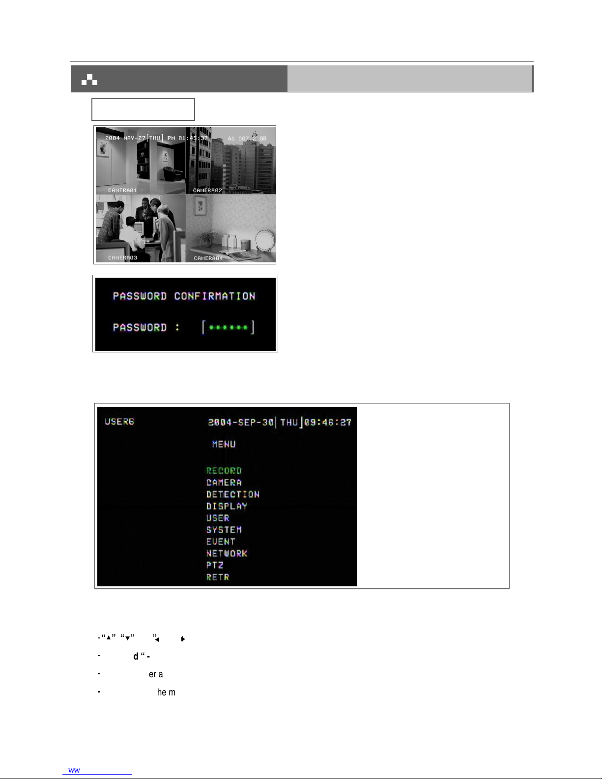
!%&
RECORD -------- Record Scheduling
CAMERA -------- Camera Setup
DETECTION ---- Motion / Alarm Setup
DISPLAY -------- Display Mode Setup
USER ------------ User Password Setup
SYSTEM -------- System Setup
EVENT ---------- Event List
NETWORK ----- Network Setup
PTZ --------------- PTZ Camera Setup
RETR--------------RETR Setup
Press “MENU” button to enter the main menu at first time.
The default password is 000000. Pleas press “ENTER” menu six
times to enter the menu when the password is default value.
There are 10 options available in the Main Menu.
The following buttons are used for menu setting :
“
” “
” “ ” “ ” : Move the cursor.
“ + ” and “ - ” : Select the numbers/ change values.
ENTER : Enter a submenu mode / an option under a submenu for browsing / Confirm the selection.
MENU : Enter the menu mode / Confirm the change/ Exit a menu.
9

!
1. STOP RECORD
The system will stop manual recording function during the recording period if the setting is “NO”. And then, press the
“ENTER” button to save the changed value.
Note: 1. The users have to stop recording function on this menu because the users cannot stop it by pressing
any front-panel buttons during the recording period.
2. On the Timer Recording mode, users have to either change the RECORD METHOD setting from TIMER
to MANUAL or change the timer setting to stop the timer recording function.
2. FRAME / SEC
Select the recording speed. The options are as following : NTSC
30
15
5 PAL
25
12
4
3. QUALITY
There are four image qualities : BEST, HIGH, NORMAL, BASIC.
4. HDD OVERWRITE
To set the HDD OVERWRITE. When the HDD is going to be full under O/W recording mode, previously recorded files
will be overwritten without further warning notices if the HDD OVERWRITE is “ON”.
5. RECORD METHOD
There are two recording methods: MANUAL ( by pressing the “REC” button) and TIMER ( by setting the timer recording).
***On the Timer Recording mode, users have to either change the RECORD METHOD setting from TIMER to
MANUAL or change the timer setting to stop the timer recording function.
Press the “
” “
” “ ” “ ” buttons to move the cursor.
Press the “+” “-” buttons to change the digit.
Press the “MENU” button to confirm the changes/ to exit the menu.
10

&'"
Press the “
” “
” “ ” “ ” buttons to move the cursor.
Press the “+” “-” buttons to change the digit.
Press the “MENU” button to confirm the changes/ to exit the menu.
1. DAY
Choose the day for recording. The options are:
MON(Monday) , TUE (Tuesday), WED (Wednesday), THR (Thursday), FRI (Friday), SAT (Saturday),SUN (Sunday),
MO-FR (Monday to Friday), SA-SU (Saturday to Sunday), OFF, and DAILY(on each day).
* Date could be changed by “+” and “-” buttons.
2. START
The beginning of recording time.
3. END
The end of recording time.
11
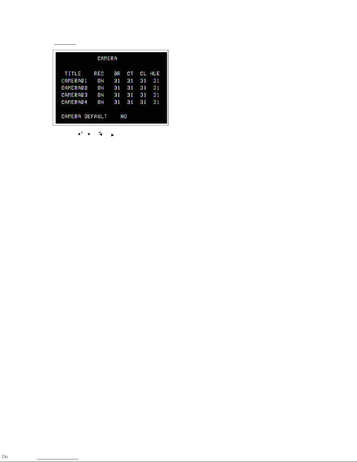
&
Press the “
” “
“ ” “ ” buttons to move the cursor.
Press the “+” “-” buttons to change the option/digit.
Press the “MENU” button to confirm the changes/ to exit the menu.
1. TITLE
Assign a title to each channel. The default title is the camera’s number (Up to 8 characters).
2. REC (RECORD)
Select a channel to record.
ON : when the timer input is triggered, DVR will record a video.
OFF : DVR will not record.
3. BR (BRIGHTNESS)
Adjust the brightness of each channel. The level is from 0 to 63.
4. CT (CONTRAST)
Adjust the contrast of each channel. The level is from 0 to 63.
5. CL (COLOR)
Adjust the color of each channel. The level is from 0 to 63.
6. HUE (HUE)
Adjust the hue of each channel. The level is from 0 to 63.
7. CAMERA DEFAULT
The setting of BR/CT/CL/HUE will be back to the default value, which is 31.
12

Press the “
” “
” “ “ ” “buttons to move the cursor.
Press the “+” “-” buttons to change the option.
Press the “MENU” button to confirm the changes/ to exit the menu.
!
1. DET (DETECTION)
The motion detection on each channel can be turned ON or OFF individually.
2. AREA
Press the “ENTER” button to set target-area.
In this function, it is defaulted to detect nothing.
After entering the setting, users will see the pink area, which means the undetected area, and users can set the area to
be detected, and which will turn from pink to transparent.
The Pink target represents the undetected area.
The Transparent target represents the Motion Detection Area.
The beginning of Motion Detection Setting-
Non activate area
Motion Detection Setting-
One Target undetected
Motion Detection Setting –
A row-target detected
Motion Detection Setting –
A detected target
!
: navigates between targets.
-: turns all targets on the screen ON/ OFF.
+ : press once to set a motion target, press twice to set a row of motion target..
13

3. LS (Level Sensitivity)
Comparing the difference between two images to allow the system to start motion detection function.
Lower number = higher sensitivity for motion detection. The highest sensitivity setting is 02, the lowest sensitivity setting
is 15. The default value is 06.
4. SS (Spatial Sensitivity)
Set the number of motion detection targets (from 0-192 target areas). The highest sensitivity setting is 0, and the lowest
sensitivity setting is 15. The default setting is 02.
Note:The setting of Spatial Sensitivity cannot be more than the number of targets set in the AREA.
5. TS (Temporal Sensitivity)
The system will start the motion detection function if the continuous fields are all different.
The highest sensitivity setting is 0, and the lowest sensitivity setting is 15. The default setting is 02.
6. RE (REFERENCE)
Set the Reference image to which the current screen is compared (from 0-63).
For example, the value 8 would compare the current image to the 8
th
previous image. The higher value will increase the
sensitivity. The default value is 10.
7. Alarm
Select LOW / OFF / HIGH for alarm polarity. The default alarm value is LOW.
8. Duration Time
You can set durative time of detection.(1, 2, 3, 4, 8, 24, 60), the default value is 02.
9. Day, Start, End of Duration
Choose the day for recording, the beginning of recording time and the end of recording time.
Note: When the motion detection function is triggered during the recording period. The symbol will be
shown.
When the alarm function is triggered during the recording period. The symbol will be shown .
14

!"#
Press the “
” “
” “ ” “ ” buttons to move the cursor.
Press the “+” “-” buttons to change the option/digit.
Press the “MENU” button to confirm the changes/ to exit the menu.
1. TITLE DISPLAY
Set the title showing on monitor.
2. OSD COLOR
Select the OSD (On Screen Display) color. The options are WHITE, RED, YELLOW, CYAN, BLUE, PINK, GRAY,
ORANGE.
3. CURSOR COLOR
Select the cursor color. The options are RED, YELLOW, GREEN, CYAN, BLUE, PINK, GRAY, ORANGE.
NOTE: The setting of OSD COLOR and CURSOR COLOR cannot be the same.
4. LOSS SCREEN
Select a way to display the screen when the video input is out of order. The options are BLACK, BLUE and RETAIN
(retain the last picture).
5. OSD POSITION
Select the OSD POSITION. The options are NORMAL (in upper right corner) or CENTER.
6. PLAYBACK METHOD
Select a video type to playback. The options are frame and field. 1 frame equals two fields.
7. PIP OPTION / DWELL OPTION(refer to p.16 and 17)
To enter the PIP setting menu/DWELL setting menu.
YES
15

Press the “
” “
”buttons to move the cursor.
Press the “+” “-” buttons to change the option.
Press the “MENU” button to confirm the changes/ to exit the menu.
1. FULL SCREEN
The full screen background picture display.
2. PIP SCREEN
The picture with a 1/9 size screen “insert”.
3. POSITION
There are six position settings : D/L (Down/Left), D/M (Down/Middle), D/R (Down/Right), U/L (Up/Left), U/M (Up/Middle),
U/R (Up/Right).
"""
16
Table of contents
Other CPcam DVR manuals

CPcam
CPcam CPD571 User manual

CPcam
CPcam CPD505ZHD User manual

CPcam
CPcam CPD537 User manual

CPcam
CPcam CPD548D User manual

CPcam
CPcam 262Z User manual

CPcam
CPcam CPD541D User manual

CPcam
CPcam CP-NVR-8CH User manual

CPcam
CPcam CPD500W User manual

CPcam
CPcam CPD560A User manual

CPcam
CPcam 8/16 CH MPEG-4 DVR User manual


Popular DVR manuals by other brands

NCast
NCast PR-720-R Reference manual

Dahua
Dahua General 960H Mini 1U series user manual

Ubiquiti
Ubiquiti UniFi Video UVC-NVR-2TB quick start guide

Safety Vision
Safety Vision OBSERVER 4816-NVR Hardware user's guide

SB
SB SB-MV309 instruction manual

Godrej Appliances
Godrej Appliances Eyetrace Elite ET 8L1E User's installation and operation manual


