CPcam CPD505ZHD User manual

311Z
717ASV_715ASV_QUICK_V0.9
DIGITAL VIDEO RECORDER
QUICK START
Please read instructions thoroughly before operation and retain it for future reference.

1. SPECIAL NOTES
Disclaimer
We reserve the right to revise or remove any content in this manual at any time. We do not warrant or assume any
legal liability or responsibility for the accuracy, completeness, or usefulness of this manual. The content of this
manual is subject to change without notice.
For the actual display and operation, please refer to your DVR in hand.
VGA Output Resolution Support
Users are allowed to change the resolution depending on their display monitor.
Go to “ADVANCE” “ ” “DISPLAY”, and move to “VGA OUTPUT” to select the VGA resolution you want.
There are seven options as follows:
1). 800 x 600
2). 1024 x 768 (default)
3). 1280 x 1024
4). 1440 x 1050
5). 1400 x 900
6). 1680 x 1050
7). 1600 x 1200
Note: To have the best image quality on your LCD monitor, make sure (1) the selected DVR VGA output
resolution is supported by your monitor, and (2) the VGA output settings on both the LCD monitor
and DVR are consistent.
If the image is not positioned or scaled properly, please go to your monitor’s menu for adjustment.
For details, please refer to the user manual of your LCD monitor.
2. FRONT AND REAR PANEL
2.1. Front Panel
1) LED Indicators
POWER: The DVR is powered on.
STANDBY: The DVR is in the standby mode.
HDD: The HDD is reading or recording.
HDD Full: The HDD is full.
ALARM: An alarm is triggered.
TIMER: Timer recording is turned on.
PLAY: The DVR is in the playback mode.
REC: The DVR is in the recording mode.
2) USB port
To quickly backup or upgrade firmware/OSD, you can insert a compatible USB flash drive into this USB port.
Before using the USB flash drive, please use your PC to format the USB flash drive as “FAT32” first.

3) EJECT
Press to open / close the DVD writer (optional).
4) MENU
Press to enter the main menu.
5) ENTER
Press to confirm the setting.
6) SLOW
In the playback mode, press to slowly play the file.
7) ZOOM
In the live or playback mode, press to enlarge the image of the selected channel.
8)
Press to switch the channel display mode.
9) SEQ.
Press to activate the sequence function, and press again to escape the sequence mode.
10) AUDIO (SLOW + ZOOM)
Press “SLOW” + “ZOOM“ to select live or playback sounds of the audio channels.
11) PTZ ( + SEQ)
Press “ ” + “SEQ” to enter / exit the PTZ control mode.
12) 1 ~ 8 (for 8CH) or 1~16 (for 16CH)
Press one of the buttons to select the channel to display.
13) LIST
To quick search the recorded files by events, press “LIST” to show the full list.
Select one item in the list, and press “ENTER” to playback the selected file.
14) REC
Press to activate manual recording if the manual recording function is turned off.
15) X(Play)
Press to play the latest recorded video clip.
16) (PAUSE / UP / +) / ▓(STOP / DOWN / -) / ◄◄ (REW / LEFT) / ►► (FF / RIGHT)
‧ In the playback mode, press PAUSE / STOP / REW / FF to pause / stop / fast rewind / fast forward the
playback file.
‧ In the menu, press UP / DOWN / LEFT / RIGHT to move the highlight up / down / left / right. In the setting
mode, press UP / DOWN to change the setting in the menu.
17) POWER
Press long enough to turn on/off your DVR.
Note: Under the recording mode, please stop recording before turning off your DVR.
Note: To ensure that your DVR works constantly and properly, it's recommended touse anUPS,
Uninterruptible Power Supply, for continuously operation. (Optional)
2.2. Rear Panel
1) 75Ω/ HI-IMPEDANCE
When using LOOP function, set the impedance switch at your DVR rear panel to HI-IMPEDANCE to decrease
interferences. Otherwise, switch to 75Ω.
Note: The default setting is 75Ω.
2) LOOP / INPUT (1 ~ 16CH / 1 ~ 8CH)
LOOP: Video output connector.
INPUT: Connect to video sources, such as cameras.
Note: If you want to make a video backup with audio, please make sure whether your DVR supports the
audio function, and connect audio cameras to the channels which support the audio function.
3) MONITOR
Connect to MAIN monitor for video output.
4) CALL
Connect to CALL monitor to show the channel display one by one.
When any alarm is triggered, CALL monitor will show the image of the triggered channel for a period of time.
5) Audio IN
Connect to audio sources, such as cameras equipped with the audio function.
Please get to know whether your DVR supports the audio function, and how many audio inputs are supported
first.
Note: This DVR series supports four audio-in channels, which are Audio 1, Audio 2, Audio 3 and Audio 4
accordingly, and the audio data will be recorded with the video data of CH1, CH2, CH3 and CH4
respectively.
6) Audio OUT
Connect to an audio device, such as a microphone or speaker.
7) IR
Connect the IR receiver for remote control.
8) EXTERNAL I/O
Insert the supplied 25PIN DSUB to this port for connecting external devices (external alarm, PTZ camera, etc).
For detailed I/O port PIN configuration, please refer to the user manual.
9) RS-485
Connect to external devices (such as a speed dome camera) with RS485-A and RS485-B wires.
10) VGA
Connect to a LCD monitor directly.
11) LAN
Connect to Internet by LAN cable.
12) LINK ACT.
When your DVR is connected to the Internet, this LED will be on.
13) DC 19V
Connect to the supplied adapter.
3. CONNECTION AND SETUP
3.1. HDD Installation
The HDD must be installed before the DVR is turned on.
Step 1: Loose the screws on the upper cover and open the upper cover of the DVR.
Step 2: With the rear panel facing you, there are three HDD brackets.
2-1: To install the HDD to the right bracket, slide the HDD with the PCB side facing up to the bracket, and
fix it to the bracket with two screws for each side.
2-2: To install the HDD to the left or middle bracket, remove the bracket, and slide the HDD with the PCB
side facing up to the bracket. Fix the HDD to the bracket with two screws for each side.
Step 3: Connect the power connector and data bus connector to the HDD(s) connected.
Step 4: For HDD installation to the left or middle bracket, replace the HDD bracket back to the DVR base.
For HDD installation to the right bracket, skip this step.
Step 5: Close the upper cover of the DVR, and fasten all the screws you loosened in Step 1.
3.2. Camera Connection
The cameras must be connected and power-supplied BEFORE the DVR is turned on. The DVR will automatically
detect the video system of the connected camera(s) (NTSC / PAL), and switch itself to the correct system.
Connect the camera with the indicated power supply, and connect the camera video output to the DVR video input
port with a coaxial cable or RCA lines with BNC connectors.
Note: For detailed DVR video input / output ports, please refer to “2.2. Rear Panel” at page 3.
For detailed camera operation, please refer to its own manual.
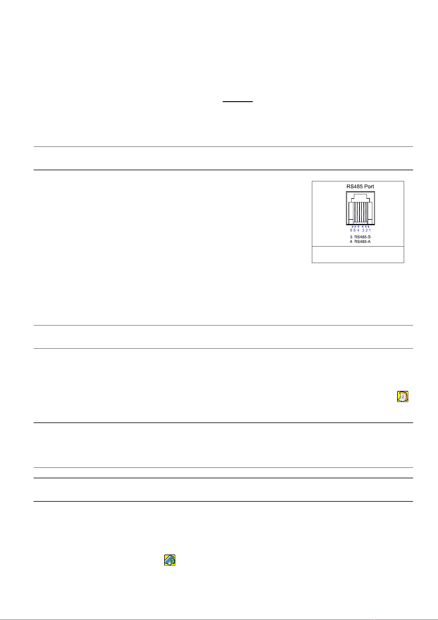
Example of RS485 port on the
DVR rear panel.
If you want to make a video backup with audio, please connect audio cameras
to the channels which support the audio function. The audio channels are CH1, CH2,
CH3 and CH4.
For speed dome cameras, make sure the RS485 control cable is connected
correctly to the RS485 port on the DVR rear panel. For details, please refer to your
speed dome camera user manual. Then, make sure the camera title, ID, protocol &
baud rate are properly configured. For details, please refer to “5.5 REMOTE” in DVR
user manual.
3.3. Power Setup
This device should be operated only with the type of power source indicated on the manufacturer’s label. Connect
the indicated AC power cord to the power adapter, and plug into an electrical outlet. The power LED will be on.
Note: To ensure that your DVR works constantly and properly, it's recommended touse anUPS,
Uninterruptible Power Supply, for continuously operation. (Optional)
3.4. Date and Time Setting
Before operating your DVR, please set the date and time on your DVR first.
Press “MENU” and enter the password to go to the menu list. The default admin password is 0000. Move to “ ”
and you can set the date / time / daylight saving in the “DATE” menu list.
Note: Please DO NOT change the date or time of your DVR after the recording function is activated.
Otherwise, the recorded data will be disordered and you will not be able to find the recorded file to
backup by time search. If users change the date or time accidentally when the recording function
is activated, it’s recommended to clear all HDD data, and start recording again.
Note: For the first time to use the DVR, please charge the DVR for at least 48 hours continuously after the
date & time is set correctly.
3.5. Password Setting
Press “MENU” and enter the password to go to the menu list. Then, Move to “ADVANCE” to enter the advanced
setting menu.
In the “ADVANCE” menu, move to “ ”. Select “PASSWORD” and press “ENTER” to enter the submenu to set
the password (four digits). The default admin password is 0000.

3.6. Record Setting
By defaults, the record function is activated when the DVR is powered on and a camera is connected.
To change the record settings, press “MENU” and enter the password to go to the menu list. Then, Move to
“RECORD” to enter the advanced setting menu. You can set the image size, image quality and the image per
second for recording.
For details, please refer to the user manual.
4. BASIC OPERATION
4.1 Live Page
Depending on the DVR you have, you may see the following live view screen with status icons.
Icon Function Icon Function Icon Function Icon Function
Key lock Key unlock 1st live audio channel 2nd live audio channel
3rd live audio channel 4th live audio channel
1st playback audio
channel
2nd playback audio
channel
3rd playback audio
channel
4th playback audio
channel
Audio channel
unselected Digital zoom mode
Digital zoom
unselected Timer recording Motion Recording
Alarm HDD overwrite R.E.T.R. ON R.E.T.R. Delay
4.2. Recording
1) Continuous Recording Icon
When the DVR is properly connected with camera, you can see the icon “ ” (recording) on the screen.
2) Event Recording Icon
When the motion / alarm detection is activated, once motion or external alarm happens, you will see the icon
“ ” (motion) or “ ” (external alarm) on the screen.
3) Timer Recording Icon
When the timer record is activated, you will see the icon “ ” (timer) on the screen.

Note: The audio source connected to the “Audio 1” will be recorded with the video of the “CH1”.
The audio source connected to the “Audio 2” will be recorded with the video of the “CH2”.
The audio source connected to the “Audio 3” will be recorded with the video of the “CH3”.
The audio source connected to the “Audio 4” will be recorded with the video of the “CH4”.
Note: A new log will be added in the system log when the HDD data is overwritten or the recording starts
after DVR reboots.
4.3. Playback
Press “X” on the DVR control panel, and the device will playback the latest recorded video.
Note: There must be at least 8192 images of recorded data for playback to work properly. If not, the
device will stop playback. For example, if the IPS is set to 30, the recording time should be at least
273 seconds (8192 images / 30 IPS) for the playback to work properly.
1) Fast Forward / Fast Rewind
You can increase the speed for fast forward and rewind on this device. In the playback mode:
Press “►►“ once to get 4X speed forward and press twice to get 8X speed, etc. And the maximum speed is 32X.
Press “◄◄“ once to get 4X speed rewind and press twice to get 8X speed, etc. And the maximum speed is 32X.
Note: During playback, the image size of the recorded data (FRAME, FIELD or CIF) will be shown on the
screen.
2) Pause / Image Jog
Press “PAUSE” to pause the playback.
In the pause mode:
Press “X” once to get one frame forward.
Press “W” once to get one frame rewind.
3) Stop
Press “▓” under the playback mode, and the screen of this device will return to live monitoring mode.
4) Slow Playback
Press “SLOW” to get 1/4X speed playback and press twice to get 1/8X speed playback.
5) Audio Playback
Press “SLOW” + “ZOOM” to select the live or playback sound of the audio channels.
Icon “ ” means: Live audio of the 1st audio channel / Icon “ ” means: Playback audio of the 1st audio channel
Icon “ ” means: Live audio of the 2nd audio channel / Icon “ ” means: Playback audio of the 2nd audio channel
Icon “ ” means: Live audio of the 3rd audio channel / Icon “ ” means: Playback audio of the 3rd audio channel
Icon “ ” means: Live audio of the 4th audio channel / Icon “ ” means: Playback audio of the 4th audio channel
Icon “ ” means: The audio channel is not selected.
Note: If you want to make a video backup with audio, please make sure whether your DVR supports the
audio function, and connect audio cameras to the channels which support the audio function (CH1,
CH2, CH3 & CH4).
4.4. Search
1) Full Search
Press “”LIST” on the DVR control panel to show the list for all types of the recorded files. Choose the log you want
to see, and press “ENTER” to start playback.
2) Search by Time
Press “MENU” to enter the menu list, and go to “ADVANCE” l“ ”. Move to “QUICK SEARCH”, and press
“ENTER” to enter the quick time search menu. You can search any specific events by time (Year / Month / Day /
Hour / Min) and directly play the file you find.
4.5. Firmware / OSD Upgrade
4) Use USB to upgrade firmware or OSD
Step 1. Format the USB memory device as FAT 32 format first.
Step 2. Get the upgrade files from your distributor, and save the upgrade files in your USB flash device (do not
change the file name).
Step 3. Insert your USB flash drive into the USB port. Wait till the DVR detects your USB flash drive.
Step 4. Press “MENU”, and move to “ADVANCE” l“ ”. Select “UPGRADE” l“START”, and press “ENTER”.
Step 5. Select “YES”, and press “ENTER” to confirm the upgrade.
5) Use AP software to remotely upgrade firmware or OSD
Step 1. Save the upgrade files at your PC (do not change the file name), and log into the Video Viewer.
Step 2. Click “ ” (Miscellaneous Control) to show the miscellaneous control panel. In the miscellaneous control
panel, click “ ” (Tools) on the miscellaneous control panel to enter the upgrade window.
Step 3. Enter the user name, password, IP address and port number of the DVR.
Step 4. Click “Firmware” or “Language” tab as needed, and click “Add” to select the firmware or OSD files to
upgrade.
Step 5. Click “Update Firmware” or “Update Language” button to start the upgrade.
Table of contents
Other CPcam DVR manuals

CPcam
CPcam CPD541 User manual

CPcam
CPcam 8/16 CH MPEG-4 DVR User manual

CPcam
CPcam CPC-500 User manual

CPcam
CPcam CPD560A User manual

CPcam
CPcam 8CH MPEG-4 User manual

CPcam
CPcam CPD571 User manual

CPcam
CPcam CPD500W User manual

CPcam
CPcam CPD537 User manual

CPcam
CPcam CPD541D User manual

CPcam
CPcam 4 CH Digital Video System User manual


Popular DVR manuals by other brands


Panasonic
Panasonic Showstopper PV-HS2000 operating instructions

Securitytec
Securitytec DVRMP4 user manual

Sheng Jay Automation Technologies
Sheng Jay Automation Technologies K12-Pro manual

TD
TD Prime 4 Instructional manual

Tablo
Tablo DUAL 128GB quick start guide

Euro Video
Euro Video EVD-16/400A16HC Installation & operation