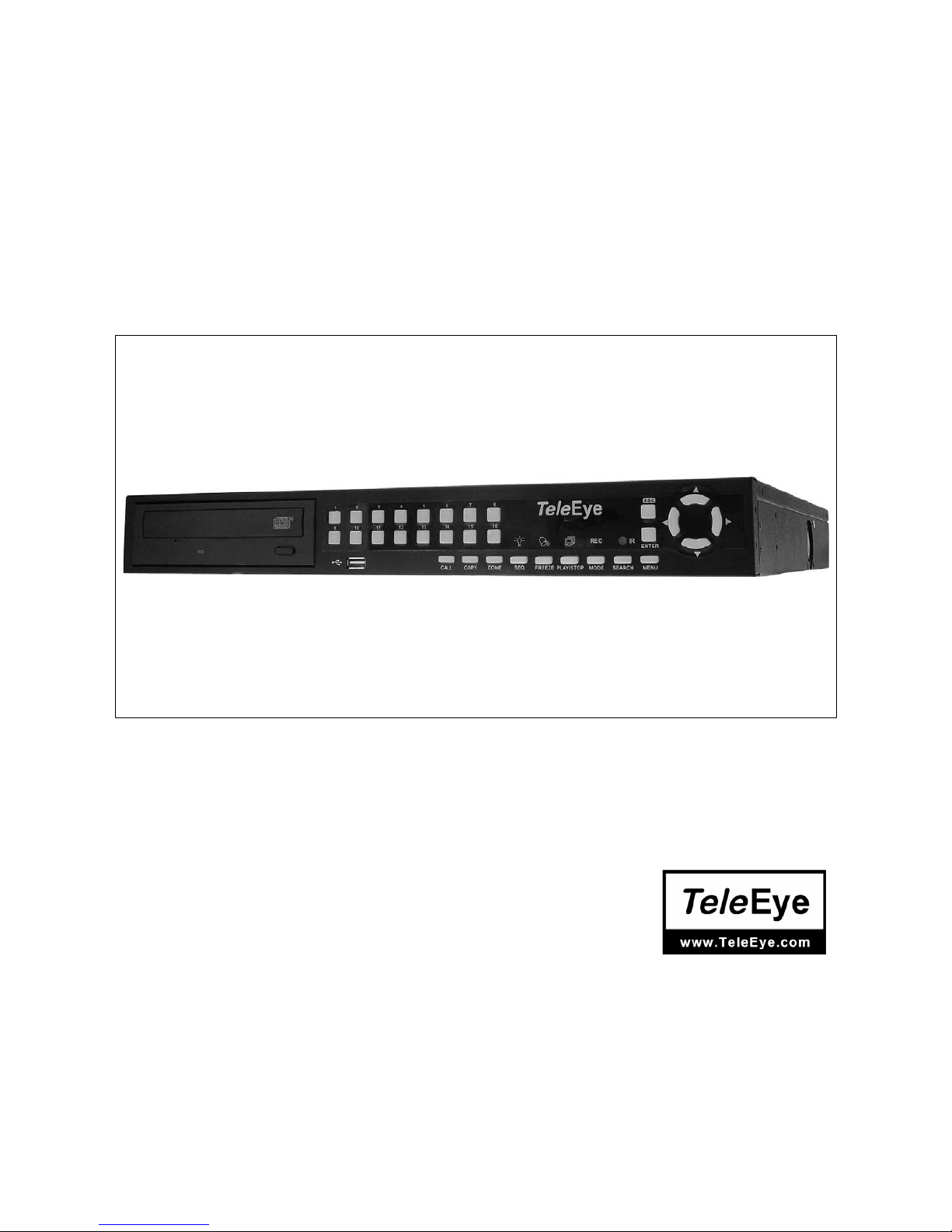
TeleEye RN684 User manual
00P3DG090TSEB2
User’s Manual
TeleEye RN684 / RN688 / RN6816
Before using the product, please
read this manual carefully.

User’s Manual
1
Notice:
Signal Communications Limited reserves the right to make improvements to the product
described in this manual at any time and without prior notice.
This manual is copyrighted. All rights are reserved. This manual may not be copied,
reproduced or translated in whole or part without prior consent from Signal Communications
Limited.
Tele Eye is a trademark of Signal Communications Limited and is registered in China, Hong
Kong, US and other countries.
TeleEye's products are sold under the brand name of CAMERIO in Australia, Japan, Korea,
New Zealand, Taiwan and Argentina.
CAMERIO is a trademark of Signal Communications Limited and is registered in Australia,
Japan, Korea, New Zealand, Taiwan and Argentina.
All other trademarks are the property of their respective owners Copyright (c) 2007 Signal
Communications Limited (A Member of TeleEye Group). All rights reserved.
Version 2.1
Limits of Liability and Disclaimer of Warranty
Signal Communications Limited has taken care in preparation of this manual, but makes no
expressed or implied warranty of any kind and assumes no responsibility for errors or
omissions.
No liability is assumed for incidental or consequential damages in connection with or arising
out of the use of the information or accessories contained herein.
Features and specifications are subject to change without prior notice.

User’s Manual
2
Caution and Preventive Tips
•Switch the 115/230V selector to your local voltage standard
•Handle with care, do not drop the unit
•Mount the unit in an equipment rack or place it on a solid, stable surface.
•Indoor use only. Do not place the unit in a humid, dusty, oily, or smoky site.
•Do not place it in an area with poor ventilation or in an area close to fire or other sources of
heat. Doing so may damage the unit as well as cause fire or an electric shock.
•When cleaning is necessary, shut down the system and unplug the unit from the outlet
before uncovering the top cover. Do not use liquid cleaners or aerosol cleaners. Use only
a damp cloth for cleaning.
•Always shut down the system prior connecting or disconnecting accessories, with the
exception of USB devices.
•Lithium battery: Danger of explosion if battery is incorrectly replaced. Replace with the
same or equivalent type of batteries recommended by the manufacturer. Dispose used
batteries according to the battery manufacturer’s instructions.
This symbol intends to alert the user to the presence of important operating and
maintenance (servicing) instructions in the literature accompanying the
appliance.
This symbol intends to alert the user to the presence of unprotected “Dangerous
Voltage” within the product’s enclosure that may be strong enough to cause a
risk of electric shock.

User’s Manual
3
Important Information
Before proceeding, please read and observe all instructions and warnings in this manual.
Retain this manual with the original bill of sale for future reference and, if necessary, warranty
service. When unpacking your unit, check for missing or damaged items. If any item is missing,
or if damage is evident, DO NOT INSTALL OR OPERATE THIS PRODUCT. Contact your
dealer for assistance.
Rack Mounting
Consult with the supplier or manufacturer of your equipment rack for the proper hardware and
procedure of mounting this product in a safe fashion. Avoid uneven loading or mechanical
instability when rack-mounting units. Make sure that units are installed to get enough airflow for
safe operation. The maximum temperature for rack-mounted units is 40 °C. Check product
label for power supply requirements to assure that no overloading of supply circuits or over
current protection occurs. Mains grounding must be reliable and uncompromised by any
connections.

User’s Manual
4
Table of Content
1. Overview .......................................................................................................................6
2. System Setup................................................................................................................7
2.1 Position the Unit...................................................................................................7
2.2 Selecting Video Format........................................................................................7
2.3 Connecting Devices to the Unit............................................................................8
2.4 Rear Panel Connections......................................................................................8
3. General System Setup ...............................................................................................10
3.1 Front Panel Introduction ....................................................................................10
3.1.1 LED Definition ......................................................................................10
3.1.2 Function Keys....................................................................................... 11
3.2 Power Up / Down the Unit .................................................................................13
3.3 Entering OSD Setup Menu ................................................................................13
3.4 System Date / Time Setting ...............................................................................14
3.4.1 Set Date / Time.....................................................................................15
3.4.2 Daylight Saving Time............................................................................16
3.4.3 Network Time Protocol Setup ...............................................................17
3.5 Record Schedule / Quality Setting .....................................................................18
3.5.1 Schedule Setup ....................................................................................18
3.5.2 Preset Record Configuration ................................................................19
3.5.3 To Record Event Video Only ................................................................19
3.5.4 ezRecord Setup....................................................................................19
3.5.5 Circular Recording................................................................................20
3.5.6 Purge Data ...........................................................................................21
4. Basic Operation..........................................................................................................22
4.1 Viewing Live / Playback Video ...........................................................................22
4.1.1 Viewing Modes .....................................................................................22
4.1.2 Digital Zoom .........................................................................................23
4.1.3 Viewing Live Cameras..........................................................................23
To Freeze Live Image..............................................................................23
4.1.4 Viewing Recorded Video ......................................................................23
Key Usage in Playback ...........................................................................24
Pause Playback and Single Step Forward ..............................................24
Viewing Live Image in Playback Mode....................................................25
4.2 Sequence Setup ................................................................................................25
4.2.1 Sequence with Main Monitor ................................................................25
4.2.2 Sequence with Call Monitor (8ch and 16ch only) .................................26
4.3 Searching Recorded Video ................................................................................26
4.3.1 Searching by Time................................................................................27

User’s Manual
5
4.3.2 Searching by Event ..............................................................................27
4.4 Video Export ......................................................................................................28
4.4.1 ezBurn Introduction ..............................................................................29
4.4.2 To Export Normal Video........................................................................29
4.4.3 To Export Event Video..........................................................................30
4.5 Dome Control.....................................................................................................30
4.5.1 Dome Connection.................................................................................31
4.5.2 Dome Protocol Setup ...........................................................................31
4.5.3 RS485 Setup........................................................................................32
4.5.4 Dome Controlling Keys.........................................................................32
4.5.5 Setting Preset Points............................................................................34
4.5.6 Calling Preset Points ............................................................................35
5. Remote Monitoring Software.....................................................................................36
5.1 Remote Monitoring System Requirements ........................................................36
5.2 Getting Start of Installation.................................................................................37
5.2.1 Changing Internet Settings...................................................................37
5.2.2 Installing Remote Monitoring Software .................................................39
5.2.2.1 Log in / Log off ........................................................................40
5.2.2.2 Software Upgrades .................................................................41
5.3 Basic Operation for Monitoring remotely............................................................41
5.3.1 To View Live Video ...............................................................................42
5.3.1.1 Selecting Display Mode ..........................................................42
5.3.1.2 Operating Cameras with Dome Control ..................................43
5.3.2 Instant Recording .................................................................................44
5.3.2.1 Recording Video Instantly .......................................................44
5.3.2.2 To Playback Instant Recorded Video ......................................44
5.3.3 To Take a Snapshot ..............................................................................44
5.3.4 To Playback Video................................................................................45
5.3.4.1 Playing Back Remote Video....................................................45
5.3.4.2 To Playback Local *.drv Files ..................................................46
5.3.4.3 Playback Controls ...................................................................47
5.3.5 Search from Event List .........................................................................48
5.3.6 Remote Monitoring Software Trouble Shooting Guide .........................49
Appendix A: Technical Specifications ...........................................................................50
Appendix B: Remote Controller .....................................................................................51
Appendix C: Setting up a DVR behind a Router ...........................................................53

User’s Manual
6
1. Overview
The Proficient MPEG-4 Series DVR is an integrated digital video recorder
that combines the features of a time-lapse audio / video recorder, a
multiplexer, and a video server to create a single security CCTV solution.
Its outstanding triplex operation enables users to view live or playback
recorded video, remotely access through network simultaneously while
recording other video, and to view wanted recorded video instantly by
entering the time and date or selecting recorded video from the event list.
The DVR series unit includes the remote viewing and configuration software
that is a Web-browser plug-in, allows user to view live or recorded video
images and enables remote configuration. The remote software is stored in
the DVR series unit and deployed over a LAN, WAN or Internet connection to
remote Windows-based computers. This simplifies the installation and
maintenance of the software components so all remote users are kept up to
date.
The DVR series unit offers advanced features not typically found in standard
multiplexers; it integrates the full features of a DVR, multiplexer and video
server (by using the remote software). The key features of the DVR series
unit are listed as follows.
Advanced Functions
•Triplex Operation: Live /Playback, Record, Network
•Supports up to 2 internal HDDs
•Supports internal CD-RW
•Supports NTP for time synchronization
•Supports Mobile View software
•Multi-language support
•Multiple built-in dome camera control protocols
•Supports Pre-Alarm Recording
•Motion Detection Marker
•Remote software for remote monitoring
User’s Manual
7
Human Technology:
•ezBurn™ for quick video export
•ezRecord™ for quick recording setting
•ezDDNS™ for automatic DDNS configuration
•IR Remote Control (Optional)
•Compact Control Keyboard (Optional)
2. System Setup
The notices and introduction on system installation will be described
particularly in this chapter. Please follow the description to operate the unit.
In order to prevent the unit from data loss and system damage that caused by
a sudden power fluctuation, use of an Uninterruptible Power Supply (UPS) is
highly recommended
2.1 Position the Unit
First, note to position / mount the DVR series unit in a proper place and be
sure to power off the unit before making any connections. The placed location
should avoid hindering or blocking the unit from airflow. Enough airflow is
needed to protect the unit from overheating. The maximum allowable
temperature of operating environment is 40°C.
The unit utilizes heat-conducting techniques to transfer internal heat to the
case, especially to the bottom side of the unit.
NOTE: Be sure the rubber feet are not removed, and always leave a
space for air ventilation on the unit’s bottom side.
2.2 Selecting Video Format
The DVR series unit is designed to operate under either NTSC or PAL video
formats. The switch is positioned on the rear panel.

User’s Manual
8
2.3 Connecting Devices to the Unit
This section lists some important notices that should be read before making
any connection to the DVR series unit.
Connecting Required Devices
Before power up the unit, you should connect cameras and a main monitor to
the unit for basic operation. If needed, connect a call monitor for displaying
full screen video of all installed cameras in sequence.
Connecting Short-term Device
If you plan to install any short-term devices to the DVR series unit and use
them as part of the unit system, such as USB CD-ROM, USB Hard Disk Drive,
etc, make sure those devices are connected only after the unit is powered up.
The reason is because the DVR series unit can recognize the external
devices only after the power-up process is done completely.
2.4 Rear Panel Connections
There are various connectors on the rear panel for the DVR series unit
installations. The following figure shows the connectors by name; and
followed by the detailed description of each connector.
Main Monitor (BNC/ VGA)
BNC and VGA output connectors are offered for
connecting to a main monitor. The main monitor
displays live image and playback recorded video in
either full-screen or split-window format. VGA output
connector is optional.
Call Monitor(for 8ch and 16ch Models only)
The call monitor is used to display full screen video of
all installed cameras in sequence. The BNC call
monitor connector allows user to connect the DVR
series unit with an optional call monitor.
User’s Manual
9
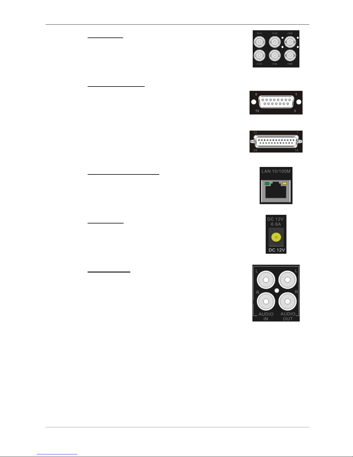
Video Input
16 BNC connectors are offered for video input
streams from installed cameras. The number of
connectors is equal to the number of channels.
Alarm I/O & RS485
The unit provides an alarm I/O and RS485 port that
offers user the flexibility required to connect the unit to
the other device. The definitions for pins varies when
the DVRs have different channels. Refer to Setup
Guide for detailed pin definitions.
4ch model
8ch/16ch models
LAN Connector (RJ-45)
The DVR series unit is capable of networking. The
LAN port opens the door of the DVR series unit to
Ethernet where by the Internet.
Power Jack
The DVR series unit has a free voltage DC power
connection jack. Please connect the power adapter
that ships with the unit.
Audio In / Out
The DVR series unit provides two channels of audio
recording and playback. Audio In RCA connector is
offered for connecting an audio source device (e.g.
external amplified microphone) to the unit; Audio Out
RCA connector is offered for connecting an audio
output device (e.g. amplified speakers) to the unit.

User’s Manual
10
3. General System Setup
The DVR series unit allows user to access some general operations through
the front panel easily. The following subsections introduce the general
operations of the unit.
The regular displayed OSD information and its displayed positions are shown
as following figure. The channel title will be displayed on the top-left side of
the window, either in full screen mode or in multiple channel mode. The
current operating mode, including Call mode, Dome-Control mode, Playback
mode. Freeze mode and Sequence mode, will be displayed on the
bottom-left side of the screen. And the date/ time information will be display
on the bottom-right side.
Ch4
►*1
2005/11/09 PM04:31:22
3.1 Front Panel Introduction
The front panel controls enable user to control the unit and preset the
programmable functions.
3.1.1 LED Definition
The LEDs on the front panel of the DVR series unit are described as follows.
Power LED (Green)
The LED lights up when the correct power is connected
to the unit.
Alarm LED (Red)
The LED lights up when an alarm is triggered.
REC LED (Green)
The LED blinks while the DVR series unit is recording.

User’s Manual
11
Network LED (Green)
The LED lights up when the DVR series unit is
connected to a network and blinks when the data is
being transferred.
3.1.2 Function Keys
This section describes the functional keys, which are for normal operation, on
the front panel of the DVR series unit.
Please refer to the Setup Guide for the graphical illustration of functional
keys.
CHANNEL
•In both Live and Playback modes, press the CHANNEL key to view the
corresponding video in full screen. The number of the CHANNEL keys
corresponds to the number of cameras supported by the unit.
•In dome control mode, the key “1” is used to access the Set/Go preset
menu; the key “2” is used to hide or display the dome setting parameters.
DOME
Press the key to enter dome control mode. Please refer to Section Dome
Control for detailed controlling operation.
MODE
Press repeatedly to select for wanted main monitor display format. There are
four available view modes: full screen, 4-window (2×2), 9-window (3x3), and
16-window (4x4). Refer to Section View Modes for detailed information.
SEQ (Sequence)
Press to start automatic sequencing of the video coming from the installed
cameras.
MENU
Press this key to call the OSD setup menu.

User’s Manual
12
ESC
Press to cancel or exit from certain mode or OSD setup menu without
changing the settings made previously.
ZOOM/ENTER
•In OSD menu or selection interface, press this key to make the selection
or save settings.
•In live full screen view mode, press this key to view a 2×zoom image;
press it again to exit zoom mode.
COPY
In Playback mode, press COPY to select the start and end point of the video
you want to export. Refer to Section Video Export for detailed information.
PLAY/STOP
Press this key to switch between live image and playback video.
NOTE: The video of latest 5 ~ 10 minutes cannot be played back
because the video is still saved in the buffer.
FREEZE
•Press FREEZE while viewing live image, the live video will be frozen. The
date / time information shown on the monitor will continue updating. Press
FREEZE again to return to live mode.
•Press FREEZE while playing the recorded video, the playback video will
be paused. Press LEFT / RIGHT to move the recorded video reverse /
forward by single step. Press FREEZE again to continue playing video.
SEARCH
In both Playback and Live mode, the user can press SEARCH to call the
Search menu for searching and playing back recorded video by date and
time or events.
Direction Keys
•In Zoom mode, these keys function as Direction keys.
•In the OSD menu, the LEFT/ RIGHT keys are used to move the cursor to
previous or next fields. To change the value in the selected field, press
UP/ DOWN.

User’s Manual
13
3.2 Power Up / Down the Unit
If you must shut down the DVR series unit for any reason, please use the
proper shut down and power up procedures to avoid damaging your DVR unit.
To Power Up the Unit
Simply plug in the power adapter that came with the package and the DVR
will start to boot.
The color bar and system checking information will be shown on the monitor
and then disappear when the unit has been completely powered up.
To Restart / Shutdown the Unit
Press MENU and input the administrator password to access the OSD Main
menu. Select <Shutdown> in Main Menu and press ENTER to enter the
Shutdown menu, which displays as follows.
Shutdown
1. Power Off
2. Reboot
Execute
Execute
<Power Off>
Select this item to shut down the unit. Do not remove the power during shut
down until the message “You can safely turn off DVR now!” displays.
<Reboot>
Select this item to reboot the unit. The color bar and system checking
information are displayed on the monitor until the unit is completely restarted.
3.3 Entering OSD Setup Menu
The OSD Main menu contains a list of items that are used to configure the
DVR series unit. To enter the Main menu, press MENU and then enter
Administrator or User password. The Password Verification screen displays
as follows.
Password Verification
________
Press Channel Keys To Enter Password
(4-8 Digits)
Press ◄Key To Delete

User’s Manual
14
The default passwords are shown in the following table. The same passwords
are used for entering the remote viewing software DynaRemote Lite.
Administrator Password User Password
1 2 3 4 4 3 2 1
NOTE: It is strongly suggested to change the passwords to prevent
unauthorized access to the unit.
After entering the correct password, the Main menu is displayed.
Main Menu
1. System Setup
2. Monitor Setup
3. Camera Setup
4. Record Setup
5. Sequence Setup
6. Event Setup
7. Database Setup
8. Configuration
9. Shutdown
Move the cursor up / down over the OSD items using the Direction keys and
press ENTER to enter the selected sub-menu.
3.4 System Date / Time Setting
User can set the current date, time and other OSD parameters in Date/Time
menu (under System Setup Menu). The administrator’s privileges are
required for entering the submenu. In OSD Main menu, select <System
Setup> and press ENTER, then select <Date/Time> to access the Date/Time
menu; the menu displays as follows.
Date/Time
1. Date
2. Time
3. Time Zone
4. Date/Time Display
5. Date Display Mode
6. Time Display Mode
7. Date/Time Order
8. Daylight Saving Time Setup
9. Network Time Protocol Setup
2005/02/21
PM10:39:26
OFF
1 Row
Y/M/D
24 HR
Date First

User’s Manual
15
3.4.1 Set Date / Time
Set Date / Time
Select <Date> / <Time> and press ENTER for adjusting the settings. LEFT /
RIGHT keys are used to move the cursor to previous or next field, ENTER is
for selecting, and UP / DOWN are used to change the value in the selected
field.
NOTE: The new date / time setting applies to record new video. The
date and time of previously recorded video will not be changed.
NOTE: If you have to change time settings in any case, we strongly
recommend you to format the HDDs to avoid database corruption.
Date / Time Display
Users are allowed to set the time OSD displays in 1 or 2 rows. Use the UP /
DOWN keys to change the setting. The default is to display the time OSD in
one row.
Date Display Mode
This function allows user to set the OSD display type of the date. There are
three options to select from: <Y/M/D>, <M/D/Y> or <D/M/Y>. “Y” represents
“Year”, “M” represents “Month” and “D” represents “Day”.
Move to the item and press ENTER, the option starts blinking. Use UP /
DOWN keys to change the setting. The default setting is <Y/M/D> in both
NTSC / PAL formats.
Time Display Mode
User can set the time format to <12 hour> or <24 hour>. Use the UP / DOWN
keys to change the format. The default setting is <12 hour>.
Date / Time Order
The item is used to set the order of date / time display to <Date First> or
<Time First>. Use UP / DOWN keys to change the setting.

User’s Manual
16
3.4.2 Daylight Saving Time
Daylight Saving Time
The item is for those people who live in certain regions to observe Daylight
Saving Time. Select <ON> to enable, or <OFF> to disable the function.
If the function is disabled, the DST Start / End time and DST Bias will be
grayed out and cannot be accessed.
NOTE: If this function is enabled, the date/time information will be
shown on the screen with a DST icon when playing back recorded
video or searching video in the event list. “S” indicates summer time
and “W” indicates wintertime.
DST Start / End
The items are used to program the daylight saving duration. Use LEFT /
RIGHT keys to move the cursor to the next or previous field, UP / DOWN to
change the settings in the selected field.
DST Bias
The item allows user to set the amount of time to move forward from the
standard time for daylight saving time. The available options are <30>, <60>,
<90> and <120> minutes.

User’s Manual
17
3.4.3 Network Time Protocol Setup
Time Zone
Select <Time Zone> to enter the time zone. To find out your local time zone,
please visit www.greenwichmeantime.com or refer to the following figure.
NOTE: The <Time Zone> must be set to your local time zone or the
<Network Time Protocol Setup> will not be accessible.
Network Time Protocol Setup
After entering the time zone, the <Network Time Protocol Setup> option will
appear. Select the <Network Time Protocol Setup> to set the time server.
The default time server is time.nist.gov, but the user can change it to other
time servers when desired. A list of IP addresses of the time servers is listed
below.
129.6.15.28 129.6.15.29 132.163.4.101
132.163.4.102 132.163.4.103 128.138.140.44
192.43.244.18 131.107.1.10 69.25.96.13
206.246.118.250 208.184.49.9 64.125.78.85
207.200.81.113 64.236.96.53 68.216.79.113
After the time server is set, select <Manually Time Sync> to sync the time.
The time sync can also be updated periodically. Select <Automatically Time
Sync>, and the time will be automatically synced once an hour.

User’s Manual
18
3.5 Record Schedule / Quality Setting
The Record Setup menu allows user to set recording quality, recording
schedules, and other recording parameters. Administrator's password is
required to access Record Setup menu. In the Main menu, move the cursor
to <Record Setup> and press ENTER; the following menu is displayed.
Record Setup
1. Record Mode
2. Schedule Setup
3. Preset Config
4. ezRecord Setup
5. Circular Recording
6. Purge Data
720×240@60PPS
Standard
ON
3.5.1 Schedule Setup
The Schedule Setup is used to set the day and night time, or weekend
recording schedule. Select <Schedule Setup> from the Record Setup menu
and press ENTER; the following menu is displayed.
Schedule Setup
1. Day Time Start
2. Day Time End
3. Night Time Start
4. Night Time End
5. Weekend Schedule
6. Weekend Start
7. Weekend End
AM 06:00
PM 06:00
PM 06:00
AM 06:00
YES
Fri 18:00
Mon
06:00
•Make appropriate changes of the start time of Day and Night Time using
Direction keys.
•Press ENTER to confirm the settings or ESC to cancel.
•If you want to have a weekend record, choose <YES> to enable the
Weekend Schedule in advance and then set the Weekend Start/End time.
•Press ESC to return to previous page.
User’s Manual
19
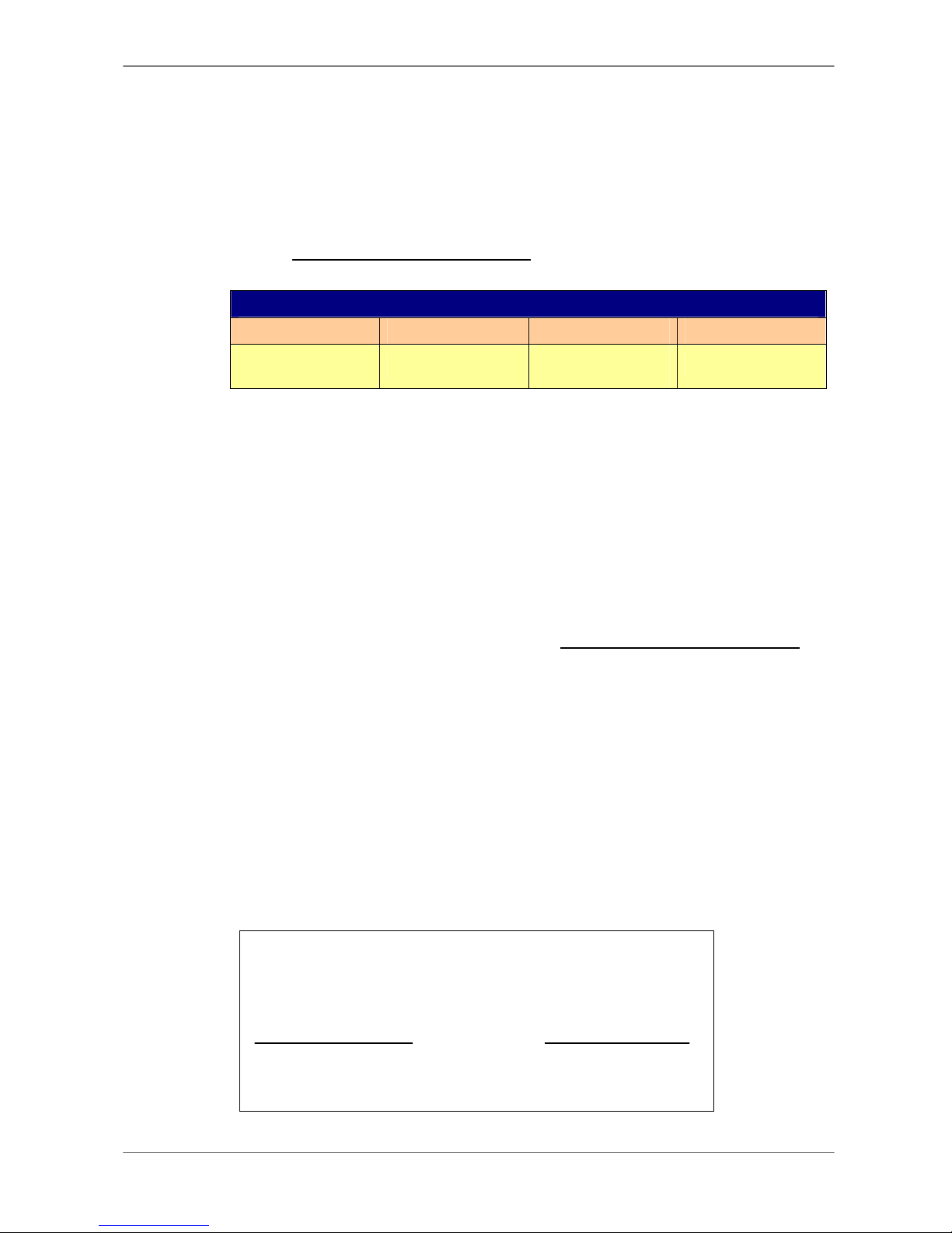
3.5.2 Preset Record Configuration
The <Preset Config> is used to select the preset recording quality and frame
rate. In normal circumstances, we strongly suggest you set the item to
<Standard>, the default. Below table shows the PPS and picture size under
<Standard> in Half-D1 mode. Please refer to OSD Menu Setup Guide,
Section Preset Record Configuration for more detailed information.
Halfl-D1 mode (NTSC: 720x240@60PPS; PAL: 720x288@50PPS)
Normal PPS Normal Size Event PPS Event Size
3.75 NTSC
(3.125 PAL) 11 KB 15 NTSC
(12.5 PAL) 17 KB
3.5.3 To Record Event Video Only
If you want your DVR unit to start recording only when the alarm is triggered,
follow the steps:
•Enter the OSD setup menu with correct password.
•In the OSD setup menu, select <Record Setup> menu. Move the cursor to
the item <Preset Config>, and select <Event only>.
Refer to OSD Menu Setup Guide, Section Preset Record Configuration for
more detailed information.
3.5.4 ezRecord Setup
This item aims to ease the complicated record settings, and to make the
setup much easier. Note that the item can be reached only when you select
<ezRecord> as the option for <Preset Config>.
Select <ezRecord Setup> from <Record Setup> and press ENTER, the
sub-menu appears as below figure:
ezRecord Setup
How Many Days To Record
Daytime Record
Night Record
Weekend Record
Average Normal PPS
Average Normal Quality
2Days
Yes
Yes
Yes
3.75
Best
Record Info
This manual suits for next models
2
Table of contents
Other TeleEye DVR manuals

TeleEye
TeleEye RX364 User manual

TeleEye
TeleEye RX504 User manual

TeleEye
TeleEye RX324_V3 User manual

TeleEye
TeleEye GX684 User manual

TeleEye
TeleEye RX538 User manual

TeleEye
TeleEye GN6516 User manual

TeleEye
TeleEye RA Series Manual

TeleEye
TeleEye GN6516 User manual

TeleEye
TeleEye RA204 User manual

TeleEye
TeleEye JN204X DVR User manual

TeleEye
TeleEye GN8816 User manual

TeleEye
TeleEye RX538 User manual

TeleEye
TeleEye GN8 Series User manual

TeleEye
TeleEye JN6400 User manual

TeleEye
TeleEye GN6516 User manual

TeleEye
TeleEye RM134 User manual

TeleEye
TeleEye GN8808 User manual

TeleEye
TeleEye RM134 User manual

TeleEye
TeleEye JN6204 User manual

TeleEye
TeleEye JN6500-S User manual


