The fence lock handle is designed so that it may be
disengaged after use on the lock nut and will hang
in a neutral position as shown. The angle between
the fence and the table may be changed for beveling
operations by loosening the fence angle lock nut. The
angle selected for the bevel cut is indicated on the
protractor scale. After changing the fence position
as described above, check carefully that the fence
angle lock nut is secure before proceeding with a cut-
ting operation.
The handwheel when turned will raise or lower the
front table, thus regulating the depth of cut as in-
dicated by the depth of cut pointer and scale.
ADJUSTMENTS:
If at any time the cut obtained should vary from that
indicated on the depth of cut scale the following
adjustment may be made. Set the front and rear
tables at the same level and check with a straight-
edge. Loosen the screw X2951 holding the pointer
29719, and shift the pointer until it indicates zero
on the scale. Tighten the screw securely after making
the above adjustment°
If a 90 ° setting of the fence angle protractor does
not produce square cuts the fence may be reset square
with the table by using an accurate tri-square. After
the 90 ° relation between the fence and table has been
established, the screw X2951 holding the protractor
pointer may be loosened and the pointer reset at 0.
If a gouge or step is produced at the end of a cut
it is an indication that the rear table is too low.
Likewise. the cut may diminish or taper as the work
is pushed through as a result of a high rear table.
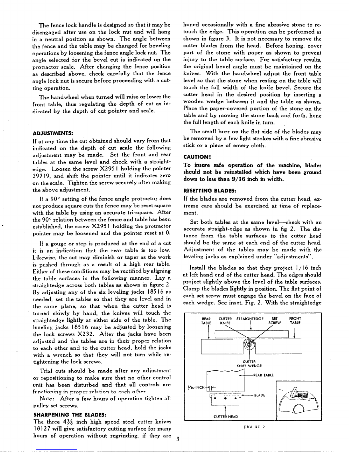
Either of these conditions may be rectified by aligning
the table surfaces in the following manner. Lay a
straightedge across both tables as shown in figure 2.
By adjusting any of the six leveling jacks 18516 as
needed, set the tables so that they are level and in
the same plane, so that when the cutter head is
turned slowly by hand, the knives -will touch the
straightedge lightly at either side of the table. The
leveling jacks 18516 may be adjusted by loosening
the lock screws X232. After the jacks have been
adjusted and the tables are in their proper relation
to each ether and to the cutter head, hold the jacks
with a wrench so that they will not turn while re-
tightening the lock screws.
Trial cuts should be made after any adjustment
or repositioning to make sure that no other control
unit has been disturbed and that all controls are
f,,ncHonin_ it) proper r_lztion to each other.
Note: After a few hours of operation tighten all
pulley set screws.
SHARPENING THE BLADES:
The three 4_ inch high speed steel cutter knives
1812 7will give satisfactory cutting surface for many
hours of operation without reg_nding, if they are
honed occasionally with a fine abrasive stone to re-
touch the edge. This operation can be performed as
shown in figure 3. It is not necessary to remove the
cutter blades from the head. Before honing, cover
part of the stone with paper as shown to prevent
injury to the table surface. For satisfactory results,
the original bevel angle must be maintained on the
knives. With the handwheel adjust the front table
level so that the stone when resting on the table will
touch the full width of the knife bevel. Secure the
cutter head in the desired position by inserting a
wooden wedge between it and the table as shown.
Place the paper-covered portion of the stone on the
table and by moving the stone back and forth, hone
the full length of each knife in turn.
The small burr on the flat side of the blades may
be removed by a few light strokes with a fine abrasive
stick or a piece of emery cloth.
CAUTION !
To insure safe operation of the machine, blades
should not be reinstalled which have been ground
down to less than 9/16 inch in width.
RESETTING BLADES:
if the blades are removed from the cutter head, ex-
treme care should be exercised at time of replace-
ment.
Set both tables at the same level---check with an
accurate straight-edge as shown in fig 2. The dis-
tance from the table surfaces to the cutter head
should be the same at each end of the cutter head.
Adjustment of the tables may be made with the
leveling jacks as explained under "'adjustments".
Install the blades so that they project 1/16 inch
at left hand end of the cutter head. The edges should
project slightly above the level of the table surfaces.
Clamp the blades lightly in position. The flat point of
each set screw must engage the bevel on the face of
each wedge. See inset, Fig. 2. With the straightedge
REAR CUTTER STRAIGHTEDGE SET FRONT
SCREW TAB|E
FIGURE 2
LDownloaded from www.Manualslib.com manuals search engine