Scell-it ELEMENT 007 User manual

CORDLESS SETTING TOOL
FOR HOLLOW WALL ANCHOR
TECHNICAL DATA SHEET
E-007
Capacity:
hollow wall anchor
of M4 to M8
Traction power:
6,000 N
Stroke:
4-40 mm
Weight (incl. battery):
1.30 kg
Autonomy:
1 battery charge =
500 hollow wall anchor
Battery:
18 V Li-ion - 2.0 Ah with
charger indicator.
Charger:
18V - battery charging time
2.0 Ah = 100% in 30 minutes
Warranty:
1 year
REFERENCE
CONTENTS
CORDLESS
SETTING TOOL
E-007
BATTERY18V
LI-ION -2.0AH
QUICK
CHARGER 18V
RIGID
CARRYING CASE
E-007-1XBAT 1 1 1 1
E-007-BODY 1
E-BATT 1
E-CHARG 1
225 mm
220 mm
210 mm
250mm
SPECIFICATIONS REFERENCES
FEATURES
Rigid
carrying case
smooth trigger and grip
Long oblong opening to prevent
tool blocked issue
Brushless motor (Coal free):
• Increase durability (reduces wear)
• Less energy (better autonomy)
• Noise reduction
Patented tool, unique worldwide.
Patent N° FR2010727
e
x
c
l
u
s
i
v
e
3 LEDs to illuminate the work zone
stroke setting knob:
• 4 to 40 mm
• pitch = 1.2 mm
e
x
c
l
u
s
i
v
e
Same battery and charger as
other ELEMENT tools
Fast charge in 30 min
V1 - 12/01/2022
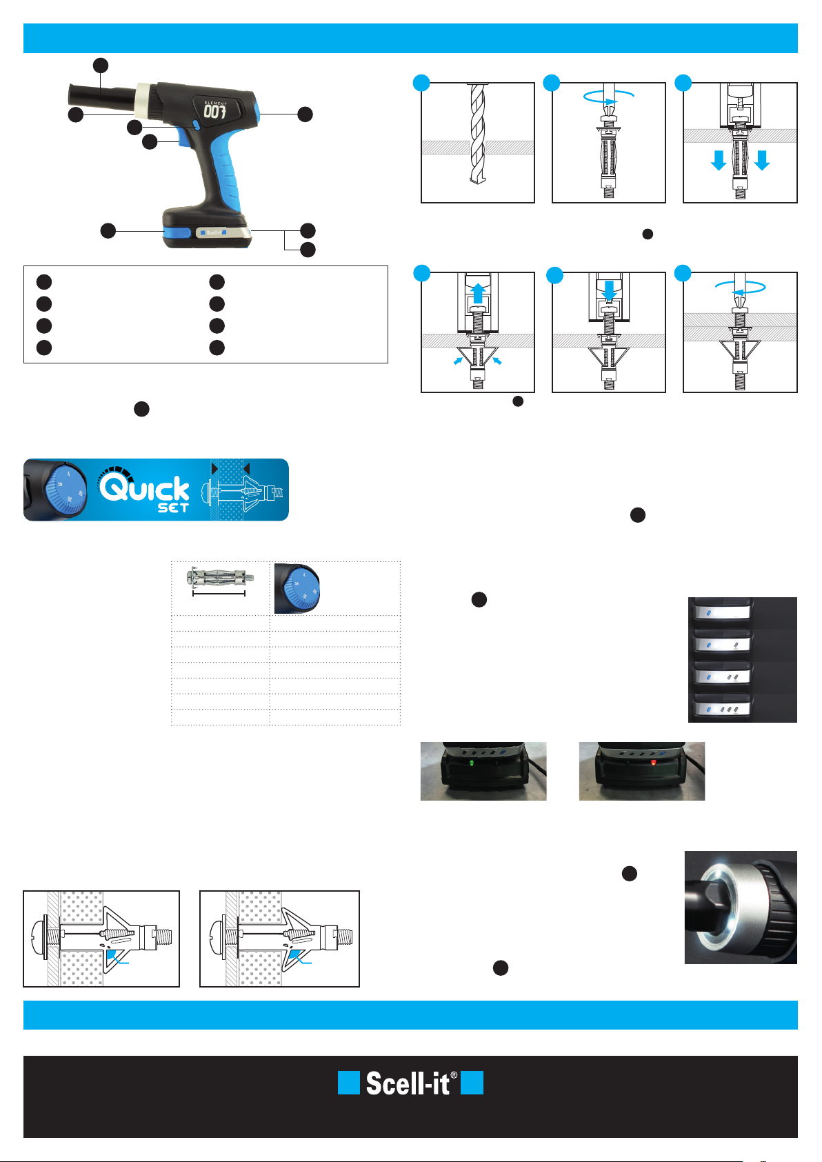
OPERATING INSTRUCTIONS
MAINTENANCE / TROUBLESHOOTING / SAFETY INFORMATION
TECHNICAL SERVICE
Beacon Industrial Estate - Weston road - Stafford ST18 0DG - Tel: 01785 246539 - [email protected] - www.scellit.co.uk
Puller
Stroke setting dial
Trigger
Unlock battery buttons
1
2
3
4
5
6
7
8
●LED LIGHTS:
The tool is equipped with 3 powerful LED lights 7to light up
the working area.
Turn on the light only
Press the trigger half way to turn on the light. The lights will
shutdown after 10 seconds.
Turn on the tool with the lights on
Press the trigger 3. The lights turn on and remain on until 10
seconds after the trigger is released.
100%
75%
50%
25%
●BATTERY LEVEL INDICATOR:
4 lights on the battery panel allows you to check the remaining power. Press and hold the
blue button 5to check the battery level:
4 lights on : 100% remaining
3 lights on : 75% remaining
2 lights on : 50% remaining
1 light on : 25% remaining
The information on the battery panel can vary (+/- 5%) due to
environmental conditions.
Green light on the charger:
the battery is fully charged
Red light on the charger:
the battery has to be charged
●REMOVE THE BATTERY:
Battery is locked to the riveting tool with a spring.
To remove the battery, press the 2 unlock buttons 4and slide the battery.
Do not force it.
1
3
8
4
7
5
2
6
See details and illustrations in user manual.
●ADJUSTING THE STROKE:
Use the stroke setting knob 2on the back of the E-007:
• The stroke range is 4 to 40mm
• Each pitch is 1.2mm
● HOLLOW WALL ANCHOR INSTALLATION:
In general, the stroke required for a perfect installation depends on the length of the hollow
wall anchor.
But this can vary according to the
different designs of the HWA on
the market.
ADVICE
Refer to the table for
recommended stroke settings.
Blank test a HWA and adjust the
setting if necessary.
HWA
LENGTH
RECOMMENDED
STROKE SETTING
(data for information
only)
mm mm
23 8-12
33-37-40 16-18
46-47-50-53 24-26
63-66 24-26-28
75 38
80 40
Battery charge test button
Battery charge indicator
LED lights
Reverse button
Drill the wall to the
recommended diameter of
the HWA.
Check «reverse button» 8is
set correctly (pressed on the
right side).
Pull the trigger to expand the
HWA and cause it to grip the
wall securely.
Slightly unscrew the screw
from the HWA to insert the
carriage of the puller 1
between the screw head and
the flange of the HWA.
Release the trigger: the puller
will automatically go back to
the initial position.
Then release the tool.
Insert the HWA into the hole:
the flange of the HWA should be
flush to the surface of the wall
(the small lugs slightly recessed
in the wall).
Remove the screw / place your
object / re-screw to fix it.
1
4
2
5
3
6
●WARNING:
E-007 does not have a clutch system. If the stroke is set too high, it could lead to damage
of the anchor or the plasterboard wall.
To avoid this, it is strongly recommended to carry out a «blank» test on a sample wall
before installing the anchor on the wall.
A good installation will be a deformation of the anchor legs between 90° to 110° (see
pictures below), which allows a good locking without damaging the wall (a slight
penetration of the legs into the wall is tolerated and even recommended for a tighter hold):
90° 110°
This manual suits for next models
1
Other Scell-it Power Tools manuals

Scell-it
Scell-it VI-P300B User manual

Scell-it
Scell-it ELEMENT FIVE User manual

Scell-it
Scell-it VI-P300B User manual

Scell-it
Scell-it PR500 User manual

Scell-it
Scell-it ELEMENT 8 User manual

Scell-it
Scell-it E-308NP User manual

Scell-it
Scell-it VI-P300 User manual

Scell-it
Scell-it ELEMENT 5 User manual

Scell-it
Scell-it ELEMENT SIX User manual


