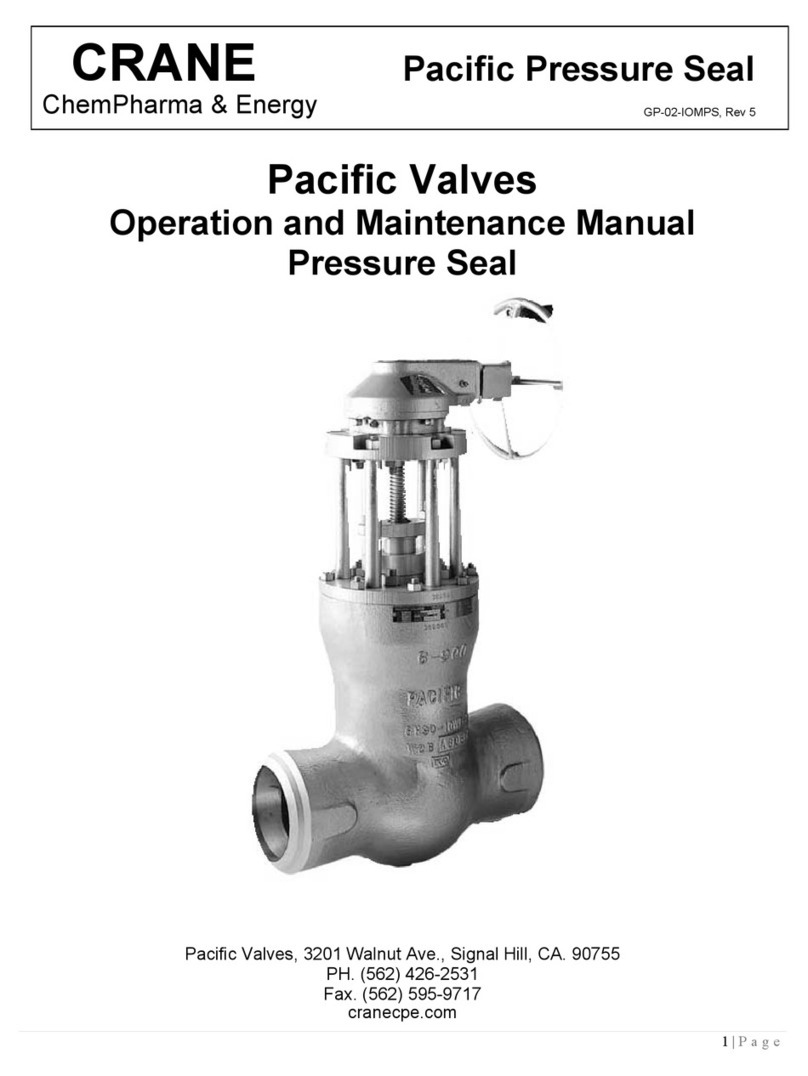
Crane KROMBACH TUFSEAT Performance Series User manual

www.cranecpe.com
KROMBACH®TUFSEAT™
Performance Series Ball Valves
TUFSEAT by KROMBACH - THE SUPERIOR MSBV
INSTALLATION, OPERATION AND
MAINTENANCE MANUAL
Floating Ball Design

www.cranecpe.com
2
Installation, Operation & Maintenance
1. General
1.1 Area of Application
This operating manual applies for ball valves produced by
Friedrich Krombach GmbH Armaturenwerke.
The operating manual also applies to identical valves from
other companies if these valves were delivered through
Krombach and the contract documents for the delivered
valves expressly mention this operating manual.
Before the valves are used, the manual must be read
carefully and completely.
If there are any discrepancies or if anything is unclear,
please contact KROMBACH.
1.2 Warning of Danger
If the following caution and warning notes are not
observed, this can lead to dangerous situations and the
manufacturer's warranty could become ineffective.
Please contact KROMBACH if you have any queries.
1.2.1 Installation, Maintenance and Operating
Personnel.
To avoid endangering persons and equipment, expert
staff must be used for fitting, maintenance and operation.
(see DIN IEC 3/B/244/CDV)
1.2.2 Carrying out fitting work on valves
Fitting work on pressurized parts of the valve may only be
carried out when the pipeline is depressurized. To prevent
pressure and/or medium being trapped inside the ball
valve, put the valve in the half-open position. The valve
must have cooled down to ambient temperature before
work is started.
Fitting work on pressurized parts of valves for caustic
or toxic flow media may only be carried out following
additional emptying and bleeding of the valve and the
respective pipeline.
Caution! Valves have dead spaces where residue (under
pressure) can remain after the flow medium has been
emptied.
The same safety requirements apply to valves as to the
pipeline system they are built into and for the control
system that is attached to the drive if appropriate. This
manual only states the safety instructions that have to be
heeded in addition for the valves.
The safety instructions listed also apply to any heating
sheath. The manufacturer's specifications are valid for
attachment parts. The manufacturer's manuals contain
additional safety instructions for the attached parts.
1.3 Product identification and marking
1.3.1 General Designation
The valve must be checked for correlation with the
specification after delivery, by the customer and before
installation in the system.
Standard-series valves produced by Krombach are marked
by:
• FK Manufacturer's mark
• Nominal size (DN or NPS)
• Nominal pressure (PN or Class)
• Material designation for valve body and cover
1.3.2 Designation with type designation plate
Valves that have been designed and confirmed for special
operating data have a name plate attached.
The name plate has the following marking:
• FK Manufacturer's mark
• (DN or NPS) Nominal diameter
• Maximum operating pressure at maximum operating
temperature in
• Model year
• Consignment figure and serial number
ATTENTION
!
ATTENTION
!
ATTENTION
!
ATTENTION
!
ATTENTION
!
ATTENTION
!
ATTENTION
!

3
www.cranecpe.com
Installation, Operation & Maintenance
1.3.3 CE Designation
Valves that are subject to CE marking are marked
additionally by:
• CE mark
• Code of the issuing office
1.3.4 Valves for Oxygen
Valves for oxygen (O2) have additional markings:
• "Oil and grease-free, suitable for oxygen"
1.4 Condition on delivery, transport and
storage
The valves are delivered with an outer coating, sealed with
protective caps, and in an open position.
Valves made of stainless steel are not coated.
The valve must be stored dry in its original pack-
aging and/or sealed with protective caps.
Sealing surfaces and threads in particular must not be
damaged mechanically or through any other factors.
Valves for oxygen are delivered sealed in film. Ship-
ping and storage must be carried out in such a way that
the film does not become damaged. Only undamaged
transport film guarantees freedom from oil and grease as
packed after manufacture.
Lifting equipment must be fixed to the valve body.
The coating, handwheel and accessory parts must not
become damaged by the lifting equipment being hooked
on.
Lifting equipment must not be hooked to handwheel
or valve spindle. ACCIDENT HAZARD! DAMAGE to the
product!
The valves should be stored in closed, dry rooms on a firm
clean base.
2. Product
2.1. Proper Use
The valves have been designed exclusively for installation
into a pipeline system to block off or guide through media.
A valve may not be used if its permissible pressure/
temperature range (="rating") is not sufficient for the
operating conditions. The permitted values can be found
on the valve name plate or the product data sheet. Special
approval is required from KROMBACH for use of the valve
outside these values.
Disregarding this regulation can lead to danger to life
and limbs and cause damage in the pipeline system.
It must be guaranteed that the parts of the valve that
come into contact with the media are made of materials
suitable for the media used. KROMBACH will not accept
liability for any damage caused by corrosion through
aggressive media.
Disregarding this regulation can lead to danger to life
and limbs and cause damage in the pipeline system.
For valves that are used as an end valve:
During normal operation, in particular with gaseous, hot
and/or hazardous media, a blind flange or cap must be
fitted to the open connection or (only suitable for short-
term use!) the valve must be safely locked in the "CLOSED"
position.
If the valve has to be opened as an end valve in a
pressurised line, this must be done extremely carefully
so that the medium sprayed out does not cause any
damage.
Be careful when closing such a valve: Danger of crushing
between housing and ball!
If a valve has to be removed from a pipeline:
Medium can escape from the pipeline or the valve.
In the case of media that can be harmful to health or are
hazardous, the pipeline has to be completely emptied
before the valve is removed. Be careful of residue that
can flow out of dead spaces in the valve or the pipeline
or have remained in the valve (under pressure).
ATTENTION
!
ATTENTION
!
ATTENTION
!
ATTENTION
!
ATTENTION
!
ATTENTION
!
ATTENTION
!
ATTENTION
!

www.cranecpe.com
4
Installation, Operation & Maintenance
Make sure that valves that have been operated at
operating temperatures of > 50°C or < 20°C and the
pipeline connections cannot be touched by the operator,
in order to protect the operator from injury.
• The usual flow speeds analogue to EN 593:2004 Table
2 must be observed during permanent operation in
the pipeline system. Abnormal operating conditions
such as vibrations, pressure surges, erosion, cavitation
and more than small shares of solids in the medium
– in particular abrasive solids – must be clarified with
KROMBACH.
• Media to be conveyed may only have a very small
share of solids that can damage or block the seal
system.
• The use of abrasive media is not recommended.
• The valves should not be used for media that are
prone to inner deposits.
• If a valve is to be used for throttling in permanent
operation, this must be agreed when the order is
placed. The application limits must always be agreed
upon with KROMBACH (agreed with KROMBACH for
cavitation free operation).
• The application limits must always be agreed upon
with KROMBACH for cavitation-free operation.
2.1.1 Method of Operation
• Ball valves are actuated using a hand lever. (Actuation
through gear/drive see 2.7.5)
• A ball with cross-hole is used as a blocking fitting,
which either releases or blocks the full medium flow
through a swivel movement of 90°.
The valve is closed by turning the hand lever to the
right (clockwise).
The valve is opened by turning the hand lever to the
left (anti-clockwise).
Respective instructions are on the hand lever itself.
• No torque-enhancing aids may be used to actuate the
valve.
2.1.2 Design and technical data
The technical design of the valves corresponds to the
enclosed documentation.
All the dimensions, materials, special versions, accessories
and any further specifications can be found in the
enclosed ORDER-RELATED DOCUMENTATION.
The images in the exploded views are only design
examples.
2.2 Installation in the Pipeline
2.2.1 General Instructions
• Before installation in the pipeline, the valve must
be checked to make sure that it matches the
specification for the installation location
• Clean the valve of storage and transport dirt
• Remove the cap from the valve
• The connection pipeline and pipeline connection
flanges must be parallel and the correct distance
apart.
• When the system is being painted after valve
installation, the stem must remain free of paint.
• When media are used at an operating temperature of
under 0°C, the valve has to be dry before it is put into
operation.
• Pipelines designed for steam to flow through them
must be routed in such a way that condensation
draining is possible and water hammers are excluded.
• If fittings are insulated, care must be taken that the
stuffing box area remains accessible and controllable
in the operating state.
2.2.2 Installation position and Direction
The ball valves can be installed in any position, but can be
restricted by accessories (e.g. drives).
The normal installation position is to be preferred > stem
vertically upright.
The installation position with the stem hanging down-
wards must be avoided because operating medium can
spill over the hand lever if the stem seal is leaking.
If there is a danger of the valves freezing, only the normal
installation position is permissible, and the valves must
have a draining fitting in the central housing section.
The mode of operation must guarantee that the valve
does not become damaged by freezing medium.
Uni-directional valves need to be installed in the preferred
direction as indicated by the arrow on the tag of the valve.
ATTENTION
!
ATTENTION
!
5
www.cranecpe.com
Installation, Operation & Maintenance
Where liquid media with great strain on the body and
cover under pressure. Heat expansion and temperature
fluctuations are used in the system. Impermissibly high
pressures can result, which place too great a strain on the
body and cover under pressure. In such cases, the valve
and the pipeline must be secured against impermissib-
ly high pressure. The dead spaces in the valve must be
secured separately by means of a pressure-relief bore hole
or other measures.
When the valve is installed in the pipeline, the arrow
on the fitting must point in the pressure direction.
Tightness in the opposite direction is not guaranteed.
2.2.3 Installation
• The valve has to be installed without tension in a
clean pipeline.
• Before the valves are installed, check that the connec-
tion dimensions of the valve flanges or the welding
end connectors match those of the pipeline.
• The flange seals must be centred.
• The fastening screws on the connection flanges must
be tightened evenly and crosswise.
• Welded valves are to be welded in place without
tension, taking technical rules into account. (Welding
and any heat treatment that may be necessary takes
place at the responsibility of the pipeline construction
company).
• The valve may not serve as an anchor in the pipeline
system; it must be carried by the pipeline.
2.3 Commissioning
• Before the valve is put into operation, check that the
correct valve has been installed in installation positi-
on according to 2.3.2.
• Check the correct position of the valve in relation to
the way the system works.
• All installation work must be completed correctly
before operation is started.
• Check the valve for leaks during and after it has been
put into operation by means of visual inspection.
2.4 Maintenance and Testing
2.4.1 Maintenance Interval
Depending on the type of system and operating data
involved, the valve will need some maintenance.
The maintenance interval must be determined by the
system owner-operator on the basis of his specific
operational experience. In particular, air tightness
and function must be checked regularly according to
operational experience or legal regulations.
CAUTION! Valves for the flow medium oxygen must
not be allowed to come into contact with unsuitable
materials, e.g. lubricants!
2.4.2 Testing Pressure
The testing pressure for recurring tests must not exceed
the value of the testing pressure at the manufacturer's.
This can be found in the valve's acceptance test
certificates.
2.4.3 Stuffing Box on Ball Valves
• Check that the stuffing box is leakproof.
• If the stuffing box is not leakproof, tighten carefully
until it is.
• Valve actuation must be guaranteed, however.
• If tightness cannot be achieved, the stuffing box
packing must be replaced.
The stuffing box packing may only be replaced when
the instructions under section 1.2 + 2.8 of this operating
manual are taken into account.
The packing ring material must be resistant to the flow
medium and be suitable for the respective operating data,
operating pressure and operating temperature.
The special packaging instructions of the packing
manufacturer must be taken into account for the different
packing materials, or the valve manufacturer must be
consulted if necessary.
ATTENTION
!
ATTENTION
!
ATTENTION
!
ATTENTION
!
ATTENTION
!

www.cranecpe.com
6
Installation, Operation & Maintenance
2.4.4 Body gaskets and packing
Check the sealing elements for tightness. If they are not
leakproof, tighten with the valve depressurised. If tight-
ness is not achieved, a new body gaskets and packing
must be used.
The sealing elements must be replaced with the valve
depressurised, the requirements of section 1.2 + 2.8 of this
operating manual must be met.
2.5 Faults and Fault Rectification
• Determine and define the type of problem.
• If the problem is caused by a heavy leak, the leak spot
should be localised if possible.
• Inform KROMBACH. (See Warranty section 2.9)
2.6 Accessories
2.6.1 Final Position Switch
The installed final position switches must be connected
according to the respective circuit diagram and checked
for correct adjustment.
2.6.2 Locking Fixtures
To prevent the valve being actuated unintentionally,
which could lead to danger, locking and catch fixtures are
available from the manufacturer.
2.6.3 Special Accessories and Versions
Additional specifications must be heeded for valves with
special accessories or for special versions.
2.6.4 Valves with Gear and/or Actuator
Special mounting, maintenance and operating instruc-
tions from the manufacturer are valid for gears and/or
drives!
Please contact KROMBACH if you have any queries.
Ball valves with gear, electric/pneumatic setting drive
are installed in the normal installation position: Stem
vertically upright (drive at the top) in the pipeline.
This installation position must be observed!
KROMBACH must be consulted if other installation
positions are required!
• The direction of rotation
(clockwise = CLOSE;
anti-clockwise = OPEN)
remains the same whether the valve is actuated by
means of the gear handwheel or the electric/pneu-
matic actuating drive!
The connection of electric cables may only be carried out
by specialised staff.
Applicable regulations, in particular VDE 0100 and VDE
0165 (explosion protection) must be heeded.
2.6.5 Retrofitting Actuators
The very wide range of operating conditions and possible
installation positions must be taken into consideration in
particular when retrofitting drives.
KROMBACH must always be consulted in such cases!
2.7 Repairs
Repairs and service work on valves may only be carried
out by the manufacturer or trained staff, see also section
1.2.
2.7.1 Repairs at the Manufacturer's
• Due to increased efforts to protect the environment
and the health of our employees, we need to know
from you which materials the ball valves to be repaired
by our employees have been in contact with.
• Our service technicians may not do any work without
this contamination declaration.
• To avoid unnecessary expenditure and delay for you
and us, we require your contamination declaration
together with the order and shipping papers in the
event of repair or replacement work (form is attached
or can be requested from us).
2.7.2 Repairs at the Operator's
If the valve cannot be repaired at the manufacturer's, this
work should be carried out by a service fitter or by trained
operator staff. Only original spare parts may be used for
this.
ATTENTION
!
ATTENTION
!
ATTENTION
!
ATTENTION
!
ATTENTION
!

7
www.cranecpe.com
Installation, Operation & Maintenance
2.7.3 Repairs at the Operator's
A repair of balls and seat rings, by grinding and polishing,
can be accomplished exclusively at the manufacturer.
If this is not possible, new parts must be used from the
manufacturer.
2.8 Warranty
The warranty for this product is regulated by the General
Terms and conditions of Krombach and with the supply
contract concluded.
• During the warranty period, the valve may only be
removed or opened with the approval of KROMBACH
or in the presence of a KROMBACH representative.
2.9 Declaration of responsibility for user
safety
NOTE - RESPONSIBILITY OF THE USER
FAILURE OR IMPROPER SELECTION OR IMPROPER USE
OF THE PRODUCTS OR RESPECTIVE PARTS DESCRIBED
IN THIS MANUAL CAN CAUSE FATALITIES, INJURY OR
PROPERTY DAMAGE.
This document and other information from Krombach
contain product or system options for further investigati-
on by users with technical know-how.
The user is solely responsible for the final selection of
system and components through examination and te-
sting, and for making sure that all the capacity, durability,
maintenance, safety and warning requirements of the
application are met. The user has to examine all aspects of
the application carefully, follow applicable industrial stan-
dards and heed the information related to the product in
the current product catalogue as well as all other docu-
ments that are provided by Krombach.
As far as Krombach delivers components or system op-
tions based on technical data or specifications that have
been provided by the user, the user is responsible for
checking that these technical data and specifications are
suitable and sufficient for all applications and reasonably
predictable purposes of application of the systems.
Trouble-Free Operation
The KROMBACH TUFSEAT Performance Series Ball Valves,
applied within their pressure and temperature limitations,
properly installed, adjusted, and operated, should require
minimum attention supplying long-term, trouble-free
service in a wide variety of applications.
READ CAREFULLY
The following procedures and illustrations have been
prepared to assist you in the maintenance and repair of
your Process Ball Valves. Please read these instructions
carefully.
Read And Understand Instructions Before
Servicing Valve
Failure to follow instructions could result in death or
serious injury. If you have any questions, please contact
the factory at +1 (513) 745-6000 in the Americas and
sales_lindau@cranecpe.com elsewhere.
These instructions have been prepared for valves as they
are currently manufactured. If you have an older design
valve that needs repair, contact either the factory or your
nearest Service Center to make sure that you have the
correct repair parts and instructions.
Maintenance
All KROMBACH TUFSEAT Performance Series ball valves
stem seals are adjusted and factory tested for tight shut-
off, normally no further adjustment is necessary. If leakage
should occur along the stem, follow the simple adjust-
ment instructions below.
Special applications may require no grease at all or require
special types of grease. Please consult factory to get addi-
tional information.
Note: Grease types
1) For seat and seat seal area surfaces in body and tail use
weicon anti-seize nickel assembly paste
2) For bolts, nuts & screws use castrol optimol paste TA
ATTENTION
!
ATTENTION
!
ATTENTION
!

www.cranecpe.com
8
Torques
Body joint bolting torques, Table-A
Axial force for pre-deforming body gasket and seat seal, Table-B
Class 150 Class 300
Valve Size Bolt QTY Bolt size Bolt Torque Valve Size Bolt QTY Bolt size Bolt Torque
(inch) (DN) (no’s) (inch) (Nm) (In-lbs) (inch) (DN) (no’s) (inch) (Nm) (In-lbs)
½” DN15 4 5/16”-18UNC 16 142 ½” DN15 4 3/8”-16UNC 28 248
¾” DN20 4 5/16”-18UNC 16 142 ¾” DN20 4 3/8”-16UNC 28 248
1” DN25 4 5/16”-18UNC 16 142 1” DN25 4 3/8”-16UNC 28 248
1 ½” DN40 4 7/16”-14UNC 45 398 1 ½” DN40 4 ½”-13UNC 70 620
2” DN50 4 7/16”-14UNC 45 398 2” DN50 4 5/8”-11INC 70 620
3” DN80 4 5/8”-11INC 140 1239 3” DN80 4 5/8”-11INC 140 1239
4” DN100 8 ½”-13UNC 140 1239 4” DN100 8 5/8”11INC 140 1239
6” DN150 8 ¾”-10UNC 240 2124 6” DN150 16 ¾”-10UNC 240 2124
Valve Size & Pressure Class Body gasket Ball (seat seal)
DN NPS Class / PN F [kN] F [kN]
15 ½” 150-300 / 10-40 38,6 1,6
20 ¾” 150-300 / 10-40 57,7 2,6
25 1” 150-300 / 10-40 57,7 3,8
40 1 ½” 150-300 / 10-40 90,9 8,0
50 2” 150-300 / 10-16 90,9 12,8
50 2” 300 / 25-40 98,0 12,8
80 3” 150-300 / 10-40 134 29,7
100 4” 150-300 / 10-40 272 48,8
150 6” 150-300 / 10-40 399 110

9
www.cranecpe.com
Torques Stem Seal Adjustment
KFO1156: HIGH TEMPERATURE TRIMKFO1176: STANDARD TRIM
STEM SEAL ADJUSTMENT (Threaded Packing Gland)
Sizes: 1/2”-2” Cl.150 & 300, 3” Cl.150 (1156, 1176)
To adjust for leakage along the valve stem, turn the
Threaded Packing Gland (#8) clockwise in approximately
1/3- turn increments to compress the packing (#13). Use
torques from following table.
Note: If a tight seal cannot be obtained, continue with the
instructions for valve repair.
Valve Size Pressure Class Threaded Packing
Gland size
Threaded Packing Gland Torque
KFO1176 KFO1156
(inch) (DN) (Class) (metric) (Nm) (in-lbs) (Nm) (in-lbs)
½” DN15 #150 & #300 M30 116 1026 116 1026
¾” DN20 #150 & #300 M30 116 1026 116 1026
1” DN25 #150 & #300 M30 116 1026 116 1026
1 ½” DN40 #150 & #300 M36 224 1982 224 1982
2” DN50 #150 M36 224 1982 224 1982
2” DN50 #300 M48 390 3452 390 3452
3” DN80 #150 M48 390 3452 390 3452

www.cranecpe.com
10
Stem Seal Adjustment
STEM SEAL ADJUSTMENT (Bolted Packing Gland) Sizes:
3” Cl.300, 4”-6” Cl.150 & 300 (1156, 1176)
To adjust for leakage along the valve stem, turn the
packing adjustment bolts (#21) (6pcs or 8pcs) clockwise, in
approximately 1/2-turn increments to compress packing
gland (#8) and packing (#13). Use torques from following
table. (When tightening packing bolts, use proper
crisscross adjustment pattern as shown below).
Note: If a tight seal cannot be obtained, continue with the
instructions for valve repair
Valve Size Pressure Class Packing Gland
Bolt size Quantity
Packing Gland Bolts Torque
KFO1176 KFO1156
(inch) (DN) (Class) (inch) (no’s) (Nm) (in-lbs) (Nm) (in-lbs)
3” DN80 #300 7/16” 6 27 239 18 159
4” DN100 #150 7/16” 6 27 239 18 159
4” DN100 #300 7/16” 8 24 212 17 150
6” DN150 #150 7/16” 8 24 212 17 150
6” DN150 #300 1/2” 8 44 389 44 389
KFO1156: HIGH TEMPERATURE TRIM
KFO1176: STANDARD TRIM
6 - bolts
1
2
3
4
5
6
8 - bolts
Packing Adjustment

11
www.cranecpe.com
Stem Seal Adjustment Exploded View Floating Ball Design Standard Trim
F51, A479 UNS S31803 (1.4462)
S-Ring
S-obroč
142
17-7 PH (1.4568)
Wave springVzmet valovita141
123253GraphiteSeal ringElement vzmetni240
Steel, MildHex sock. head cap screwVijak IMBUS621
86781PTFE - Carbon filledGuide bushing
Puša vodilna
114
PackingPaket tesnil113
86780PTFE - Carbon+Graphite filled /
AISI 301 (1.4310)
Spring energized lip sealVzmetno podprto tesnilo112
59923A194 Gr.8MHeavy hex nut
Matica močnejša
811
A193 Gr.B8M Cl.2StudVijak stojni810
86779
A479 316Ti (1.4571); 316 (1.4401)
Support Ring
Obročpodporni
19
93686
F51, A479 UNS S31803 (1.4462)
Packing glandPrirobnica pritisna18
86777TFMSX Stem sealSX spod. tesnilo vretena17
A182 F316L (1.4404)+coating
SeatTesnilo krogle26
86716PTFE/Graphite/316TiBody gasket
Tesnilo ohišja
15
86770
F51, A479 UNS S31803 (1.4462)
StemVreteno14
A182 F316L (1.4404)+coating
BallKrogla13
A351 CF8M (1.4408) - dual certif.
Tail
Ohišje desni del
12
A351 CF8M (1.4408) - dual certif.
Body
Ohišje levi del
11
Datum
Izdelal
Pregledal
Videl
Merilo Objekt:
Ime
ARMATURE d.o.o.
Koroška cesta 55
SI-2366 Muta / Slovenija
Načrt Št.:
Zamenjuje:
Zamenjan:
Floating Design, Ball valve - bare stem
NPS3 Class300, CF8M, Standard Design
22.06.2020
Sakpal D.
Krajnc D.
Brložnik J.
49 243 08 010*
1 : 1.5
Izdelan iz:
®
CRANE
Paziti na zaščitno opozorilo po ISO 16016!
Pay attention to protection note ISO 16016!
Sprememba / Change note
Index Opis/Description Datum/Date Odob./Appr.
first issue 22.06.2020 Sakpal D.
Pridržujemo si pravico do tehničnih sprememb!
The parts are subject to change by technical innovation!
Poz.
Item
Kos
Qty. Opis Designation Material Ident št.
Item No.
Rezervni del / Spare part
Opombe k izdelavi / Assembly notes
1. Moment Poz.11 / Torque Item 11: 140 Nm
2. Pred pritegovanjem matic Poz.11 ohišje stisniti na blok za preoblikovanje tesnila krogle /
Before screwing Item 11 body parts must be pressed to block to predeform seats
3. Navoj Poz.8 je lakho dvignjen nad prirobnico 0 do 1 mm. / Thread end of item 8 can
raise over top of flange for 0 to 1 mm.
4. Namazati navoje vijakov in naležne površine matic z: / Lubricate screw threads and nut
bearing faces with: Castrol Optimol paste TA.
5. Kroglo po montaži namazati z: / Oil ball after assembly with: Baysilone Oil M100
Masa / weight: ca. N/A
4
8
14
21
7
12
9
41 42 40 6
10
5
3
640
211
1
13
Item Quantity Description Carbon Steel Stainless Steel
ASTM DIN ASTM DIN
1 1 Body A216 WCB 1.0619 A351 CF8M 1.4408
2 1 Tail A216 WCB 1.0619 A351 CF8M 1.4408
3 1 Ball A182 F316L+coating 1.4404+coating A182 F316L+coating 1.4404+coating
4 1 Stem A276 Gr.431 1.4057 A276 Gr.431 1.4057
5 1 Body gasket PTFE/Graphite/316SS PTFE/Graphite/1.4571 PTFE/Graphite/316Ti PTFE/Graphite/1.4571
6 2 Seat A182 F316L+coating 1.4404+coating A182 F316L+coating 1.4404+coating
7 1 SX Stem seal TFM TFM TFM TFM
8 1 Packing gland A479 316Ti; 316SS 1.4571; 1.4401 A479 316Ti ; 316SS 1.4571; 1.4401
9 1 Support ring A479 316Ti; 316SS 1.4571; 1.4401 A479 316Ti ; 316SS 1.4571; 1.4401
10* 8 Stud A193 Gr.B7 A4-70 A193 Gr.B8M Cl.2 A4-70
11* 8 Heavy hex nut A194 Gr.2H A4-70 A194 Gr.8M A4-70
12 1 Spring energized
lip seal
PTFE - Carbon+Graphite
filled/AISI 301
PTFE-Carbon+Graphite
filled/1.4310
PTFE - Carbon+Graphite
filled/AISI 301
PTFE - Carbon+Graphite
filled/AISI 301
13 1 Packing set Graphite Graphite Graphite Graphite
14 1 Guide bushing PTFE - Carbon filled PTFE - Carbon filled PTFE - Carbon filled PTFE - Carbon filled
21* 6 Hex socket head cap
screw A193 B8M Class 2 A4-70 A193 B8M Class 2 A4-70
40 2 Seal ring Graphite Graphite Graphite Graphite
41 1 Wave spring 17-7 PH 1.4568 17-7 PH 1.4568
42 1 S-ring F51, A276 UNS S31803,
A276 316L, A276 316 Ti 1.4462; 1.4404; 1.4571 F51, A276 UNS S31803,
A276 316L, A276 316 Ti 1.4462; 1.4404; 1.4571
Floating Ball Design
Datum
Izdelal
Pregledal
Videl
Merilo Objekt:
Ime
ARMATURE d.o.o.
Koroška cesta 55
SI-2366 Muta / Slovenija
Načrt Št.:
Zamenjuje:
Zamenjan:
Izdelan iz:
®
CRANE
4
16
4
16
4
16
8
14
21
Item Quantity Description Carbon Steel Stainless Steel
ASTM DIN ASTM DIN
16 2 Parallel key 316SS/316Ti A4/1.4571 316ss/316Ti A4/1.4571
6” class 300 oating ball design with key connection item 16
* Quantities may dier depending on the valve size

www.cranecpe.com
12
Exploded View Floating Ball Design High Temperature Trim
Datum
Izdelal
Pregledal
Videl
Merilo Objekt:
Ime
ARMATURE d.o.o.
Koroška cesta 55
SI-2366 Muta / Slovenija
Načrt Št.:
Zamenjuje:
Zamenjan:
Floating Design, Ball valve, 2-piece bare stem
NPS3 Class300 High Temp.
Izdelan iz:
®
CRANE
a
11
2
5
40
6
3
6
40
42
41
10
4
8
14
21
7
13
1
Item Quantity Description Carbon Steel Stainless Steel
ASTM DIN ASTM DIN
1 1 Body A216 WCB 1.0619 A351 CF8M 1.4408
2 1 Tail A216 WCB 1.0619 A351 CF8M 1.4408
3 1 Ball A182 F316L+coating 1.4404+coating A182 F316L+coating 1.4404+coating
4 1 Stem A276 Gr.431 1.4057 A276 Gr.431 1.4057
5 1 Body gasket PTFE/Graphite/316SS PTFE/Graphite/1.4571 PTFE/Graphite/316Ti PTFE/Graphite/1.4571
6 2 Seat A182 F316L +coating 1.4404+coating A182 F316L +coating 1.4404+coating
7 1 S2 Stem seal e-Carbon e-Carbon e-Carbon e-Carbon
8 1 Packing gland A479 316Ti ; 316SS 1.4571; 1.4401 A479 316Ti ; 316SS 1.4571; 1.4401
10* 8 Stud A193 Gr.B7 A4-70 A193 Gr.B8M Cl.2 A4-70
11* 8 Heavy hex nut A194 Gr.2H A4-70 A194 Gr.8M A4-70
13 1 Packing set Graphite Graphite Graphite Graphite
14 1 Guide bushing A582 303 coated 1.4305 coated A582 303 coated 1.4305 coated
21* 6 Hex socket head cap
screw A193 B8M Class 2 A4-70 A193 B8M Class 2 A4-70
40 2 Seal ring Graphite Graphite Graphite Graphite
41 1 Wave spring A286 1.4980 A286 1.4980
42 1 S-ring F51, A276 UNS S31803,
A276 316L, A276 316 Ti 1.4462; 1.4404; 1.4571 F51, A276 UNS S31803,
A276 316L, A276 316 Ti" 1.4462; 1.4404; 1.4571
Floating Ball Design
Datum
Izdelal
Pregledal
Videl
Merilo Objekt:
Ime
ARMATURE d.o.o.
Koroška cesta 55
SI-2366 Muta / Slovenija
Načrt Št.:
Zamenjuje:
Zamenjan:
Izdelan iz:
®
CRANE
4
16
4
16
4
16
8
14
21
Item Quantity Description Carbon Steel Stainless Steel
ASTM DIN ASTM DIN
16 2 Parallel key 316SS/316Ti A4/1.4571 316ss/316Ti A4/1.4571
6” class 300 oating ball design with key connection item 16
* Quantities may dier depending on the valve size

13
www.cranecpe.com
DIS-ASSEMBLY
1. Remove lever or operator from valve
2. Separate the body halves (#1 body & #2 tail) by
unscrewing the body heavy hex nuts (#11)
3. Remove the body gasket (#5)
4. Rotate the ball (#3) to the closed position and remove
it from the valve body
5. Rotate socket head cap screws (#21) by turning
counter-clockwise & remove the packing gland (#8)
from the body (#1) and stem (#4)
6. Remove the seats (#6), s-ring (#42), wave spring (#41)
& seal rings (#40) from the body (#1) & tail (#2). Be
careful, seat sealing surfaces should not be damage
while removing it from body (#1) & tail (#2).
7. Remove the stem (#4) by pressing it down into the
body cavity
8. Remove the packing (#13), support ring (#9), spring
energize lip seal (#12), and sx stem seal (#7) from the
body
1. Inspect the valve components for wear or damage
2. Be sure to carefully inspect the following
components for nicks, cracks, breaks, or other defects:
Seats (#6) • Ball (#3) • Stem (#4) • SX Stem Seal (#7) •
Spring Energized Lip Seal (#12) • Packing rings (#13)
• Wave spring (#41) • S-ring (#42) • Seal rings (#40) (as
shown in Exploded View)
3. The parts listed above, along with the body gasket
(5), are the only components that should require
replacement. In addition, carefully inspect the valve
body and tail.
4. Inspect the seat pockets, stem bore, packing chamber
and body joint gasket areas. Clean all areas thoroughly
to remove all signs of corrosion and media build-up.
INSPECTION
RE-ASSEMBLY
When re-assembling the valve, it is recommended that
new seal components be used to minimize the chance
of internal and external leakage. Seal kits are available
containing new seals for repairing KROMBACH TUFSEAT
Performance series ball valves. The components included
in each kit are indicated on the exploded view.
The sealing surfaces on parts must be without surface
imperfection & valve without dust or debris parties. Apply
grease coating wherever required.
Note- Seal/ repair kit includes: Body Gasket (#5), SX or S2
stem seal (#7), Spring energized lip seal (#12) (if applicable),
Packing set (#13), Guide bushing (#14), Seat seal rings (#40),
Wiper rings (#15) (if applicable).
ATTENTION
!
If lifting tools (for example ropes) are necessary to
carry the valve to the workshop the actuator should
be free from heavy load and the valve and actuator
must not be damaged.
ATTENTION
!
For shut-off valves with single-acting drives, the
drive must be in the safety position for reasons
of safety in order to exclude accidental switching
during installation. Danger to safety!
ATTENTION
!
Check the seat surface for any damage or dent marks.
Replace body, if dent marks above 1mm are found.
Assembly and Disassembly Instructions

www.cranecpe.com
14
1. Apply castrol optimal paste on short threaded part of the
studs (#10) and insert them into the body tap holes. Then
tighten the studs.
2. Insert SX stem seal (#7) over the top of the stem (#4) with
the conical surface facing the spherical stem shoulder (see
Fig. 1), slide the SX seal over the spherical portion of the
stem (see Fig. 2).
Figure 2Figure 1
3. Insert stem (#4) through the valve body cavity, allowing
the SX seal (#7) to be seated into the body counter bore.
(see Fig. 3).
4. Place the spring energized lip seal (#12) (Fig. 4a) over the
stem (#4) with the spring side facing downward into the
body (as shown in Fig. 4b) and gently push into position
(below the packing chamber).
5. Install the support ring (#9) over the stem (#4) with the
raised step facing downward until it locates at the bottom
of the packing chamber. (See Fig. 5).
KFO1176: Standard Trim
Assembly of KFO-1176 Standard Trim Floating Ball Valve
Figure 5
Stem #4
Guide Bushing #14
Packing Gland #8
Packing #13
Support Ring #9
Spring Energized Lip
seal #12
SX Stem Seal #7
Figure 4b
Figure 4a
Figure 3
Assembly of KFO-1176 Standard Trim Floating Ball Valve

15
www.cranecpe.com
Assembly of KFO-1176 Standard Trim Floating Ball Valve
6. Install one number of ‘Graphite packing ring (thick)’ &
‘Diffusion barrier ring (thin) (#13) over the Stem (#4).
7. Grease contact surfaces of Gland bushing (#14) and the
Packing gland (#8) and then insert them onto the stem and
push the stem seals deeper into the stem chamber.
8. Apply "Castrol Optimol paste TA" on the screws (#21) and
insert them into the packing gland. Slightly pre-tighten
them by hand.
9. Compress the packings to the assembly compression;
Tighten the screws incrementally to the torque specified on
the table from Page 9 or 10.
10. Rotate the stem 5 times
NOTE: Always cycle in COUNTER-clock direction to open the
ball, and in clock wise direction to close the ball.
11. Remove the packing gland along with gland bushing.
12. Repeat steps 6, 7, 8, 9 & 10, to get the stack of 4
packing rings; alternate 2 ‘Graphite packing rings (thick)’ & 2
‘Diffusion barrier rings (thin).
13. Install the Threaded Packing Gland (#8) over the
valve stem:
13.1 Threaded Packing Gland Sizes: 1/2”-2” Cl.150 & 300, 3”
Cl.150.
13.1.1 Rotate the Threaded Packing gland (#8) clockwise
until it is lightly compressing the packing (#13).
Note: Care must be taken to not cross-thread the Threaded
Packing gland (#8) and the body (#1).
Assembly of KFO-1176 Standard Trim Floating Ball Valve

www.cranecpe.com
16
Seat Assembly of KFO-1176 (Standard Trim Floating Ball
Valve)
14. Insert Wave spring (#41) into the Body part (#1).
15. Insert S-ring (#42) into the body part (#1) over the wave
spring (#41). Keep orientation of S-ring as shown in Fig.6.
16. Insert seal ring (#40) over seat "B" (#6) and insert the two
together into the valve cover (or tail) (#2). Apply grease to
the sealing surfaces of the seat (#6). Apply pressure and axial
force to pre-compress the seat seal according to the values
shown in table B.
17. Using a press, apply pressure on the seat "b" (#6) to pre-
compress the seat seal. Use a plastic spacer to protect the
seat and apply specified pressure. In the absence of a press,
contact KROMBACH for an alternative method.
18. Insert the other seal ring (#40) over seat "A" (#6) and in-
sert the two together into the body (#1) and over the "S" ring
(#42). Apply grease to the sealing surfaces of the seat (#6).
Apply pressure and axial force to pre-compress the seat seal
according to the values shown in table B and in the same
manner as done on the cover (tail) side.
19. Insert the ball (#3) into the body cavity (#1) with the port
opening in the closed position (careful not to turn the ball
180 degrees when opening and closing so that it stays as
shown in the assembly drawing in accordance to ISO 5211).
Assembly of KFO-1176 Standard Trim Floating Ball Valve
Figure 6
Assembly of KFO-1176 Standard Trim Floating Ball Valve

17
www.cranecpe.com
20. Install spiral wound body gasket (5) in the groove
of the body.
21. Join the body (#1) and tail (#2), (lettering on the halves
face the same direction). install and tighten the body stud
nuts in the crossing pattern shown in Figure 7.
22. Tighten the nuts to the torque values listed in table A.
When tightening in the crossing pattern, cycle through the
pattern at least three (3) times to assure proper and uniform
torque.
NOTE: When the valve is re-assembled, be sure the studs
protrude through the nut a minimum of one (1) thread.
23. Compress the ball with a press in order to compress the
"A" graphite ring. Use a plastic spacer to protect the ball.
4-bolts 8-bolts
1
4
3
2
5
7
8
6
4
2
3
1
5
7
8
6
4
2
3
1
12-bolts 20-bolts
5
6
4
2
3
1
7
89
10
11
12 13
14
15
16
17
18 19
20
Figure 14
9
10 11
12
Figure 7
Assembly of KFO-1176 Standard Trim Floating Ball Valve

www.cranecpe.com
18
Assembly of KFO-1156 High Temperature Trim Floating Ball Valve
KFO1156: High Temperature Trim
Figure 8
1. Apply Castrol Optimal paste on short threaded part of the
Studs (#10) and insert them into the Body tap holes. Then
tighten the Studs.
2. Insert S2 stem seal (#7) over the top of the stem (#4) with
the conical surface facing the spherical stem shoulder, slide
the S2 Seal over the spherical portion of the stem (see Fig.
8).
3. Insert Stem (#4) through the valve body cavity, allowing
the S2 Stem Seal (#7) to be seated into the body counter
bore.
4. Install one number of graphite packing ring (thick) &
diffusion barrier ring (thin) (#13) over the stem (#4).
5. Grease contact surfaces of gland bushing (#14) and the
packing gland (#8) and then insert them onto the stem and
push the stem seals deeper into the stem chamber.
6. Apply "Castrol Optimol paste TA" on the screws and insert
them into the packing gland. Slightly pre-tighten them by
hand.

19
www.cranecpe.com
Assembly of KFO-1156 High Temperature Trim Floating Ball Valve
7. Compress the packings to the assembly compression;
Tighten the screws incrementally to the torque specified on
the table from Page 9 or 10.
8. Rotate the stem 5 times
NOTE: Always cycle in COUNTER-clock direction to open the
ball, and in clockwise direction to close the ball.
9. Remove the packing gland and the gland tube.
10. Repeat steps 4, 5, 6, 7 & 8, to get the stack of 8 packing
rings; alternate 4 Graphite packing rings (thick) & 4
Diffusion barrier rings (thin).
11. Install the Threaded Packing Gland (#8) over the
valve stem:
11.1 Threaded packing gland sizes: 1/2”-2” Cl.150 & 300, 3”
Cl.150.
11.1.1 Rotate the press nut (#8) clockwise until it is lightly
compressing the packing (#13).
Note: Care must be taken to not cross-thread the press nut
(#8) and the body (#1).
Seat Assembly of KFO 1156 (High Temperature Trim)
12. Insert wiper ring (#15) into the body part (#1) & gently
push it into body groove.
13. Insert wave spring (#41) into the Body part (#1).
Figure 9

www.cranecpe.com
20
14. Insert S-ring (#42) into the body part (#1) over the wave
spring (#41). Keep orientation of S-ring as shown in Fig.9.
15. Insert seal ring (#40) over seat "B" (#6) and insert the two
together into the valve cover or tail (#2). Apply grease to the
sealing surfaces of the seat (#6). Apply pressure and axial
force to pre-compress the seat seal according to the values
shown in table B.
16. Using a press, apply pressure on the seat "B" (#6) to pre-
compress the seat seal. Use a plastic spacer to protect the
seat and apply specified pressure. In the absence of a press,
contact KROMBACH for an alternative method.
17. Insert the other seal ring (#40) over seat "B" (#6) and in-
sert the two together into the body (#1) and over the "S" ring
(#42). Apply grease to the sealing surfaces of the seat (#6).
Apply pressure and axial force to pre-compress the seat seal
according to the values shown in table B and in the same
manner as done on the cover (tail) side.
18. Careful not to turn the ball 180 degrees when opening
and closing so that it stays as shown in the assembly draw-
ing in accordance to ISO 5211.
Assembly of KFO-1156 High Temperature Trim Floating Ball Valve
This manual suits for next models
2
Table of contents
Other Crane Control Unit manuals

Crane
Crane D2003 Assembly instructions

Crane
Crane Class 150 User manual

Crane
Crane Dominator PRO Z4000 Series Assembly instructions

Crane
Crane KROMBACH 510 Manual

Crane
Crane CPV36M Series User manual

Crane
Crane Duo-Chek User manual

Crane
Crane NOZ-CHEK Cryogenic Manual

Crane
Crane CRYOFLO T-Globe User manual

Crane
Crane D1088 User manual

Crane
Crane D923 User manual
Popular Control Unit manuals by other brands

vistaCNC
vistaCNC P2-S manual

Pickering
Pickering 40-670A manual

Tranquil Ease
Tranquil Ease HC-2H operating instructions

KEY
KEY 14A Instructions and warnings for installation and use

Agilent Technologies
Agilent Technologies VXI 75000 C Series Hardware manual

Pratissoli
Pratissoli S1503 operating instructions