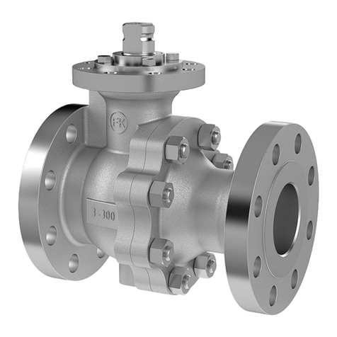
Crane KROMBACH 510 Manual

Tilting Disc Type Check Valves
04 / 2005 Operations Manual No.:
BUW-510/1-E
Operating and Maintenance Instructions
TILTING DISC TYPE CHECK VALVES
TYPE 510 with lamellar sealing

Tilting Disc Type Check Valves
Date:
prepared:
approved:
Page:
22.03.2005
C.Wied
H.Six
1 of 14
Operating instruction No.:
BUW-510/1-E
TABLE OF CONTENTS
1. INTRODUCTION ...................................................................................2
2. INTENDED USE....................................................................................2
3. SAFETY INSTRUCTIONS ......................................................................2
3.1. GENERAL SAFETY INSTRUCTIONS....................................................................................2
3.2. SAFETY INSTRUCTIONS FOR THE OPERATOR....................................................................2
3.3. SPECIAL HAZARDS..........................................................................................................3
4. LABELLING OF THE TILTING DISC TYPE CHECK VALVES ....................4
5. TRANSPORT AND STORAGE................................................................4
6. INSTALLATION INTO THE PIPELINE .....................................................5
6.1. GENERAL.......................................................................................................................5
6.2. PREPARATION FOR INSTALLATION ...................................................................................5
6.3. INSTALLATION POSITION AND DIRECTION OF FLOW ...........................................................6
6.4. STEPS FOR INSTALLATION...............................................................................................6
7. PRESSURE TESTING AND COMMISSIONING........................................7
8. NORMAL OPERATION AND MAINTENANCE ..........................................7
9. TROUBLESHOOTING GUIDE.................................................................8
10. DRAWINGS ..........................................................................................9
10.1. LIST OF PARTS .............................................................................................................9
10.2. DETAIL DRAWING >TILTING DISC TYPE CHECK VALVE<WITH FLANGES.......................10
10.3. DETAIL DRAWING >TILTING DISC TYPE CHECK VALVE<WITH WELDING ENDS...............11
11. REPAIR INSTRUCTIONS.....................................................................12
11.1. GENERAL...................................................................................................................12
11.2. REPLACING THE BEARING COVER GASKET ...................................................................12
11.3. REPLACING THE SHAFT SEALING .................................................................................12
11.4 REPLACING THE LAMELLAR SEALING …………………………………………………… 13

Tilting Disc Type Check Valves
Date:
prepared:
approved:
Page:
22.03.2005
C.Wied
H.Six
2 of 14
Operating instruction No.:
BUW-510/1-E
1.Introduction
This manual is intended to support users of tilting disc type check valves in installation, operation
and maintenance.
Danger!
If the following attention and warning notices are not followed, danger could
result, and the manufacturer’s guarantee could become ineffective.
Please contact KROMBACH in case of any questions.
2.Intended use
Tilting disc type check valves are exclusively intended, after they are installed in a pipeline system
(between flanges or by welding) and after the motor (if ordered) is connected to the control system,
to let the medium flow through in flow-through direction, but to prevent the back flow.
Tilting disc type check valves are in principle self-acting valves. The oil brake damps either the
closing or the closing and opening (according to customer request). Additional actuator parts are
mounted for special functions (order related), for example automatic closing, automatic opening
etc.
⇒Media that are to be allowed through must not contain more than a very small proportion of solid
matter.
⇒The use of tilting disc type check valves with abrasive media is not recommended.
⇒The maximum permissible pressure in conjunction with the maximum permissible temperature is
stated in the type plate of the armature.
⇒Tilting disc type check valves should not be used for media which have a tendency to build up
internal deposits.
⇒The installation of the check valves in turbulent streaming before or behind a pipe elbow is not
allowed.
⇒Section 3.2 “Safety instructions for the operator” must be observed in using the armature.
3.Safety instructions
3.1. General safety instructions
The same safety regulations apply for armatures as for the pipeline system in which they are
installed and as for the control system to which the motor is connected. The present manual only
provides such safety instructions as are to be followed additionally for armatures.
Additional safety instructions for the oil brake are contained in the manuals.
3.2. Safety instructions for the operator
It is not within the responsibility of the manufacturer KROMBACH, and must therefore be ensured
when using the armature, that:
⇒the armature is used only for the purpose for which it is intended, as described in Section 2
Danger
to life
Armatures whose pressure / temperature range (= “Rating”) is not sufficient for the
operating conditions must not be operated: the permitted value can be read from
the type plate of the armature. It is mandatory to obtain approval from KROMBACH
where the armature is to be used outside these ranges.
Failure to observe this requirement can lead to danger to life and limb and
cause damage in the pipeline system.

Tilting Disc Type Check Valves
Date:
prepared:
approved:
Page:
22.03.2005
C.Wied
H.Six
3 of 14
Operating instruction No.:
BUW-510/1-E
Danger
It must be ensured that the materials selected for the parts of the armature that
come into contact with the medium are suitable for the media used. KROMBACH
accepts no liability for damage which results from corrosion caused by aggressive
media.
Failure to observe this requirement can lead to danger to life and limb and
cause damage in the pipeline system.
⇒the pipeline system and the control system are correctly installed and regularly checked. The wall
thickness of the housing of the armature must be such that in such correctly installed pipeline
systems, an additional load Fzin the usual order of magnitude (Fz= ¶ /4 DN2PS) is taken into
account.
(PS = maximum permissible design pressure at room temperature)
⇒the armature and the drive (if ordered) are correctly connected to these systems.
⇒the activation time of the armature/drive unit is adapted to the parameters of the installation.
⇒the usual flow speeds analogously to EN593: 2002, Table 2 are not exceeded in continuous
operation in this pipeline system and that normal operating conditions such as vibrations, shocks,
erosion (e.g. due to wet steam), cavitations and more than an insignificant proportion of solid
material in the medium – particularly abrasive material – is clarified with KROMBACH.
⇒armatures which are operated at temperatures >50°C or <20°C, together with the pipeline
connections, must be protected against physical contact in order to protect the operator from
injury.
⇒installation, maintenance and operation are carried out only by properly qualified personnel (see:
DIN IEC 3/B/244/CDV).
3.3. Special hazards
Danger
to life
The valve has mounted a lever and weight. The pivoting range is necessarily
to be equipped with a protective grating.
Danger
to life
The valve shaft is sealed with a stuffing box. Before the nuts on the stuffing box
retainer are loosened or released, the pressure in the pipeline must be
completely normalised, so that no medium escapes from the stuffing box.
Danger
to life
Before releasing the bearing cover on the housing or before deinstalling the
armature from the pipeline, the pressure in the pipeline must be completely
normalised, so that the medium does not escape in an uncontrolled fashion from
the pipe. It must be ensured that the armature is open 5°-10° so that pressure
can be released on both sides of the armature. When it is necessary to deinstall
the drive, this may not be carried out until the armature has been opened for this
purpose and is left in the open position.
Danger
to life
When an armature must be deinstalled from a pipeline:
medium may escape from the pipe or from the armature. Where the medium is
hazardous to health or dangerous, the pipeline must be completely emptied
before the armature is deinstalled. Be careful with residues which subsequently
flow out of the dead spaces of the armature or out of the pipe or which
remain in the armature (under pressure).

Tilting Disc Type Check Valves
Date:
prepared:
approved:
Page:
22.03.2005
C.Wied
H.Six
4 of 14
Operating instruction No.:
BUW-510/1-E
4.Labelling of the tilting disc type check valves
Every check valve bears a label containing the following information on the type plate.
For Labelling Comment
Manufacturer KROMBACH GmbH & Co. KG
Material E.g. 1.4408 = casing material
Factory No. E.g. 34082-2005 = consecutive production no. - year of
production
DN DN (and numerical value) Numerical value in mm, e.g. DN200 or
in inches, e.g. 8”
PN /class Numerical value for PN / class PN / class = dimension standard for
flanged butterfly valves (not: pressure
range!)
PS Numerical value in bar = pressure, upper limit of use for “TS”
TS Numerical value in °C or °F = temperature, upper limit of use for
“PS”
Code E.g. KKS no.
Armatures which are subject to CE labelling are additionally labelled with
For Labelling Comment
Conformity CE, 0045 CE = manufacturer’s declaration
0045 = “notified body” - TÜV
In order that the armature can always be identified, the type label must not become damaged.
5.Transport and storage
Armatures must be handled, transported and stored with care:
⇒the armature must be stored in its original packaging and/or stored with the protective caps on the
flange connections/butt welding ends. The armature should be stored and transported on a pallet
(or similarly supported) (even at the installation site).
⇒when storing before installation, valve must be stored in a sealed dry space.
⇒the metallic seat of the armature, the oil brake and the flange connection surfaces/butt welding
ends in particular must not become damaged either by mechanical or by other influences.
⇒valves must be stored in the same way as they were delivered. The valve must not be started.
⇒transportation must be carried out with care and in accordance with the local safety regulations.
⇒for armatures with a larger nominal value, attachment and positioning of the armature must be
carried out with suitable hooks and lines the weight must be balanced in order to prevent
armatures from falling from the transport.
Danger
valves which are supplied without drive:
the armature must be transported particularly carefully. The unsecured valve disc
can open itself from the closed position under external influence (e.g. concussion).
Danger
to life
The means used to lift and transport the armature, such as hooks, lines, etc., must
be selected taking into account the weights specified in the delivery note and must
be adequately dimensioned. Lifting and transport may only be carried out by
qualified personnel.

Tilting Disc Type Check Valves
Date:
prepared:
approved:
Page:
22.03.2005
C.Wied
H.Six
5 of 14
Operating instruction No.:
BUW-510/1-E
6.Installation into the pipeline
6.1. General
The same instructions apply for the installation of armatures into a pipeline as for the connections
of pipes and similar elements of the pipeline. For armatures, the following instructions apply
additionally. Section 5 must also be observed for transportation to the installation site.
Important
Butterfly valves must be transported and installed with the valve disc closed.
Otherwise the disc could become damaged and the valve no longer sealed.
Important
There is a danger of crushing from check valves that have not been installed:
the drive (if ordered) must not be connected and activated until the butterfly
valve has been installed into the pipeline.
Note
The check valve is configured from works for the sealed closed position:
This setting of the end stops "CLOSED" in the valve body may not be changed.
6.2. Preparation for installation
⇒Ensure that no armatures are installed whose pressure class, type of connections and connector
dimensions do not correspond to the service conditions. See type plate on the armature. The
connection data for the drive must agree with the data of the control system. See type plate on
the drive.
Danger
to life
Armatures whose pressure / temperature range (= “Rating”) is not sufficient for the
operating conditions must not be operated: the permitted value can be read from
the type plate of the armature. It is mandatory to obtain approval from KROMBACH
where the armature is to be used outside these ranges.
Failure to observe this requirement can lead to danger to life and limb and
cause damage in the pipeline system.
⇒Examine valve and oil brake for transport damage. Do not install damaged valves, oil brakes or
other mounting parts.
⇒There has to be sufficient space in the pipe before and behind the valve for the disc in open
position (for example no shut-off valve mounted before and behind the check valve) so that the
disc is not damaged during the opening and opens completely.
⇒Before installation, the armature and the subsequent pipeline must be carefully cleaned of soiling,
particularly of hard foreign bodies.
⇒It is recommended that the pipeline is flushed before installing the armature.
⇒Connection ends of the armature and inner sealing surfaces are lubricated with a thin film of
grease. Before installation, carefully remove the grease conservation with a suitable solvent and
clean the interior of the armature with compressed air.

Tilting Disc Type Check Valves
Date:
prepared:
approved:
Page:
22.03.2005
C.Wied
H.Six
6 of 14
Operating instruction No.:
BUW-510/1-E
6.3. Installation position and direction of flow
⇒The check valve has to be mounted so that the arrow on the valve body coincides with the
expected flow direction through the pipe.
⇒The check valve has to be mounted with horizontal located shaft.
6.4. Steps for installation
⇒When inserting the armature (and the flange sealing) into a previously installed pipeline, the
distance between the ends of the pipeline must be measured such that all connection surfaces
(and sealings) remain undamaged.
However, the gap must not be larger than necessary, in order not to generate any additional
stresses in the pipeline.
Only check valves with flanges:
⇒The counterflange of the pipeline must be straight and coplanar.
Important
Check Valves with flange ends:
The sealing surfaces on housings with flange ends of the check valve are formed
such that the flange sealings can be used in accordance with EN1514-1 or ANSI
B16.21. The counterflange must have smooth sealing strips, e.g. Form C or D or E
in accordance with the standard EN 1092 or Stock Finish in accordance with ANSI
B16.5. Other flange forms must be agreed with KROMBACH.
Important
Check valves must be inserted into the gap between the pipeline ends with the
valve disc closed, otherwise the valve disc could become damaged and the
armature no longer sealed.
⇒Flange check valves must be centred when installing by means of the flange screws on the
counterflange before the screws are tightened.
Only check valves with butt weld ends:
⇒The butt weld ends of the armature must be straight and coplanar and must be of the same kind
as the pipe materials - see Material specification in the type plate of the armature.
Opposite butt weld ends must match each other in diameter and joint form.
⇒Welded cables may not be attached to the armature: they must be attached to the pipeline.
⇒It must be ensure through correct welding that no significant stresses are created in the pipeline
section or are transferred to the armature, and that the butterfly valve does not become damaged
by the effects of heat. Only temperatures of <300°C measured at the housing wall are
permissible.
⇒Check valves >DN300:
Important
When welding the valve into the pipeline, the welding procedure must be controlled
in such a way that the heat energy applied is limited and that the valve housing
does not become distorted. For example, the welding should be carried out
“crosswise” in order to avoid tension on the armature housing.
Failure to observe these requirements can cause distortion of the valve housing.
Distortion remaining in the seat area (the whole area near the position supports)
can make the armature unusable.

Tilting Disc Type Check Valves
Date:
prepared:
approved:
Page:
22.03.2005
C.Wied
H.Six
7 of 14
Operating instruction No.:
BUW-510/1-E
All check valves:
Danger
to life
Protective grating for lever and weight and if necessary for the oil brake has to
be mounted.
⇒With operating temperatures above 200°C, the valve casing must be insulated such that the
temperature difference between the housing and the valve disc is not more than 100°C.
⇒Adjusting of oil brake according to enclosed information sheet.
⇒The weight(s) is/are to be mounted at the end of the lever.
⇒If further actuator parts should be ordered: To complete the installation, a functional inspection
must be carried out with the signals of the control system: the armature must close and open
correctly in accordance with the control commands. The signals of the position sensor (when
present) must correctly display the position of the valve.
⇒It is essential to correct recognisable malfunctions before bringing into service. See also
Section 9 “Troubleshooting guide”.
Danger
Control commands that are incorrectly carried out could cause danger to the
operations personnel and damage to the pipeline system.
7.Pressure testing and commissioning
The pressure testing of armatures has already been carried out by the manufacturer. For the
pressure testing of a pipeline section with installed armatures, care should be taken:
⇒if the pipeline has not already been flushed before installation of the butterfly valve, this must be
carefully carried out before bringing into service. the valve disc should be open for this purpose.
⇒armature open: the test pressure may not exceed the value 1.5 x PS (according to the type
plate). (PS = maximum permissible design pressure at 20°C)
⇒armature closed: the test pressure may not exceed the value 1.1 x PS (according to the type
plate).
If an armature leakage occurs, Section 9 "Troubleshooting guide" should be observed.
8.Normal operation and maintenance
Regular maintenance work on armatures is not necessary, but there should be no external leakage
on an armature when the pipeline section is inspected. In such cases, Section 9 “Troubleshooting
guide” should be observed.
For the oil brake: Please refer to the enclosed maintenance instruction.
It is recommended that armatures which remain in a single position for long periods are activated at
least twice a year.

Tilting Disc Type Check Valves
Date:
prepared:
approved:
Page:
22.03.2005
C.Wied
H.Six
8 of 14
Operating instruction No.:
BUW-510/1-E
9.Troubleshooting guide
It is essential to observe the Safety Instructions in Section 3 when rectifying faults.
Nature of fault Action
Leakage on the bearing cover
Tighten screws.
If this does not rectify the leakage:
repair may be necessary - replace gasket. Observe the
instructions in Section 3.3 “Special hazards”. For repair
instructions, see Section 11.2.
Leakage in the seat sealing
Check whether the armature is 100% closed.
If the valve is in the closed position and
if the valve then still leaks:
repair may be necessary; replace the lamellar sealing.
Observe the instructions in Section 3.3 “Special hazards”.
Leakage at the shaft sealing
Tighten the two screws on the stuffing box retainer
alternately and in small steps each of ¼ of a revolution
clockwise.
If this does not rectify the leakage:
repair may be necessary; replace the shaft sealing. For
repair instructions, see Section 11.3.
If the nuts on the stuffing box retainer must be loosened
or unscrewed (counterclockwise):
Danger to life!
To prevent the operating personnel becoming
endangered, ensure that the pipeline on both sides of the
armature is made completely free of pressure in advance.
Observe Section 3.3 “Special hazards”.
Functional fault
oil brake closes too fast
- close more the throttle valve
- throttle valve might be damaged
- check the oil level (might be leaky, air in the
cylinder)
Functional fault
oil brake hardly to move - check the oil type for working pressure
- piston rod damaged
Functional fault
actuator / actuator parts
(if requested)
Check drive unit and control commands.
If the drive and control system are in order:
deinstall the armature (observe the instructions in Section
3.3 “Special hazards”) and inspect it.
If the armature is damaged:
repair may be necessary; obtain replacement parts and
any help that may be necessary from KROMBACH.
Corrosion If it is established after deinstallation that the housing
and/or the interior parts are not sufficiently resistant to the
medium, select parts of a suitable material.

Tilting Disc Type Check Valves
Date:
prepared:
approved:
Page:
22.03.2005
C.Wied
H.Six
9 of 14
Operating instruction No.:
BUW-510/1-E
10. Drawings
10.1. List of parts
Item Designation Item Designation
1 Body 17 Stuffing box
1.1 Body-seat 18 Stud bolt with nut
2 Disc 18.1 Option:belleville spring
3 Retainer flange 19 ÃPacking
4 Hex. head screw 20.1 End plate
5 Spring washer 20.2 Cover
6 Tapered pin 20.3 Lever
7 Plug 20.4 Weight
8 ÃGasket 20.5 Bush
9 Locating pin 20.6 Centering ring
10 ÃLamellar sealing 20.7 Hex. head screw
11 Shaft 20.8 Clamping sleeve
12 Body bearing 20.9 Fitting key
13 Ring 21 Oil brake
14 Bottom flange
15 Hex. head screw
16 ÃGasket
Ãrecommended spare parts

Tilting Disc Type Check Valves
Date:
prepared:
approved:
Page:
22.03.2005
C.Wied
H.Six
10 of 14
Operating instruction No.:
BUW-510/1-E
10.2. Detail Drawing >Tilting Disc Type Check Valve< with Flanges
Drawing does not contain any order
related special oil brake positions or
mounting positions.

Tilting Disc Type Check Valves
Date:
prepared:
approved:
Page:
22.03.2005
C.Wied
H.Six
11 of 14
Operating instruction No.:
BUW-510/1-E
10.3. Detail Drawing >Tilting Disc Type Check Valve< with welding ends
Drawing does not contain any order
related special oil brake positions or
mounting positions.

Tilting Disc Type Check Valves
Date:
prepared:
approved:
Page:
22.03.2005
C.Wied
H.Six
12 of 14
Operating instruction No.:
BUW-510/1-E
11. Repair instructions
11.1. General
⇒For selection of the correct detail drawing see Section 10.2 or 10.3.
⇒For parts list, see Section 10.1.
⇒All information from the type plate must be given when ordering replacement parts. Only original
KROMBACH parts may be installed.
11.2. Replacing the bearing cover gasket (No. 16)
Danger
to life
Before starting work release all pressure from the pipeline system, and empty it
completely!
See also Section 3.3 “Special hazards”!
11.2.1. Unscrew the screws (15), deinstall the bearing cover (14) and remove the gasket (16).
11.2.2. Check and clean the radial groove for the gasket in the cover and the sealing surfaces on
the body.
11.2.3. Lubricate the new gasket (16) with a thin film of mineral oil and place it in the bearing cover
(14). Insert the bearing cover with gasket into the housing and turn several times.
11.2.4. Clean the screws (15) and cover them with a thin film of Molykote Plus or equivalent
lubricant. Insert screws and screw tight.
11.2.5. Put the pipe under pressure. Check the tightness
11.3. Replacing the shaft sealing (Nos. 19)
Danger
to life
Before starting work release all pressure from the pipeline system, and empty it
completely!
See also Section 3.3 “Special hazards”!
11.3.1. Deinstall end plate (20.1) with lever (20.3) and the associated keys (20.9). Before
deinstallation, mark the position of the end plate on the head flange of the armature for
correct subsequent reinstallation.
11.3.2. Remove packing nuts (18) and lift off stuffing box (17). Record their arrangement for correct
subsequent reinstallation.
11.3.3. Remove packing rings (19).
11.3.4. Clean the packing space and the upper shaft end (11) cautiously and carefully.
11.3.5. Cover each new packing ring (19) outside with a thin film of mineral oil. Insert the same
number of new packing rings. For divided packing rings, the new rings must be inserted
with the division offset by 180° in each case.
11.3.6. Cover the threads of the stuffing box (17), stay bolts for the packing nuts with a thin film of
Molykote Plus or similar lubricant, and tighten the packing nuts (18) by hand.

Tilting Disc Type Check Valves
Date:
prepared:
approved:
Page:
22.03.2005
C.Wied
H.Six
13 of 14
Operating instruction No.:
BUW-510/1-E
11.3.7. Put on the end plate (20.1) and mount the keys (20.3) and lever (20.9).
Important
Do not use force to mount the end plate or the lever on the valve shaft! The
assembly should take place smoothly.
11.3.8. First tighten the packing nuts (18) equally.
11.3.9. Open and close the disc repeatedly. Check the packing nuts (18) and tighten them slightly
if necessary.
11.3.10.Pressurise the pipeline.
11.3.11.If the packing still leaks, tighten the packing nuts slowly and evenly until the leakage is
stopped. (See also Section 9 “Leakage at the shaft sealing”)
Important
Do not tighten the packing nuts (18) excessively. Otherwise the activation torque
will be increased to an impermissible level and the valve will be rough-running.
11.4. Replacing the lamellar sealing (Nos. 10)
11.4.1. Deinstall the butterfly valve from the pipeline with the disc closed. Clean the armature in
accordance with the equipment instructions or in another suitable way.
11.4.2. Open the valve disc (2) a few degrees, loosen the retaining ring screws (4) and open the
disc completely.
11.4.3. Mark the disc (2) and retaining ring (3) for correct reinstallation.
Note
For valves with low nominal width, it can be simpler to remove the drive and to turn
the disc out over the opening position in order to have more freedom of movement
for the remaining work.
11.4.4. Carefully remove the retaining ring screws (4) with the safety ring disc (5), then take off the
retaining ring (3).
11.4.5. Remove the lamellar sealing ring (10).
11.4.6. Check the seat in the housing, and if necessary clean it with solvent and fine emery cloth
(No. 600 or finer).
11.4.7. Check and clean the groove for the lamellar sealing. These area must be absolutely free of
all constituents before reassembly.
11.4.8. Insert new lamellar sealing (10) into the appropriate groove in the disc. Do not use any
force and do not damage the sealing.
11.4.9. Install the retaining ring (3) taking note of the markings (see section 11.4.3).
11.4.10.Clean the retaining ring screws (4) thoroughly and lubricate the thread with Molykote Plus
or equivalent. Insert the retaining ring screws (4) with the associated safety discs (5) and
tighten by hand.
11.4.11.Turn the valve disc in and then out twice in the seat.

Tilting Disc Type Check Valves
Date:
prepared:
approved:
Page:
22.03.2005
C.Wied
H.Six
14 of 14
Operating instruction No.:
BUW-510/1-E
11.4.12.Before installation, test wether the valve is tight. In case of leakages, the complete sealing
element is to be removed again and a sealing of 0.5 mm thinknes made of suitable material
is to be put below it. After that the sealing element hast to be fastened again.
Friedrich Krombach GmbH Armaturenwerke | Marburger Str. 364 | 57223 Kreuztal
Tel: +49-2732-520 00 | Fax: +49-2732-520 100 | www.krombach.com
CRANE Energy Flow Solutions | www.craneenergy.com ONE TEAM •ENERGIZED •TO WIN
Table of contents
Other Crane Control Unit manuals

Crane
Crane DM921 User instructions

Crane
Crane KROMBACH TUFSEAT Performance Series User manual

Crane
Crane D1088 User manual

Crane
Crane Dominator PRO Z4000 Series Assembly instructions

Crane
Crane NOZ-CHEK Cryogenic Manual

Crane
Crane D923 User manual

Crane
Crane Dominator 80mm Series Manual

Crane
Crane D1088 Manual

Crane
Crane D2003 Assembly instructions

Crane
Crane CPV36M Series User manual
Popular Control Unit manuals by other brands

ERIKS
ERIKS ECON Series Installation & operation manual

Kilsen
Kilsen KAL790 Installation sheet

CAME
CAME ZN2 user manual

Genebre
Genebre 2120 Installation, operation and maintenance manual

Wavelength Electronics
Wavelength Electronics LDTC0520 DATASHEET AND OPERATING GUIDE

Fluidmaster
Fluidmaster 400A Quick install guide