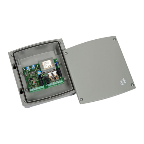
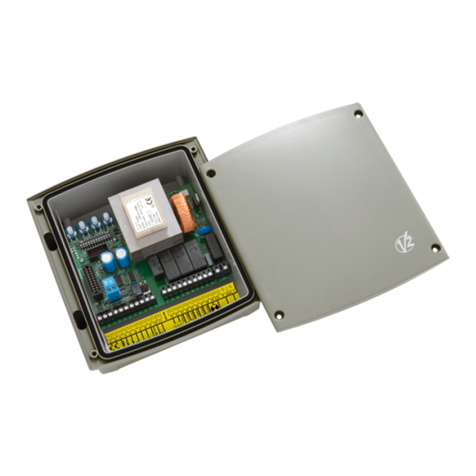
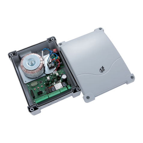
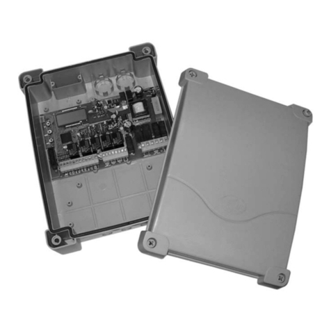
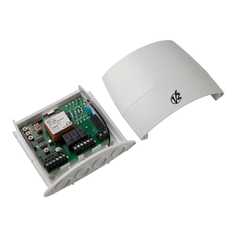
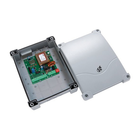
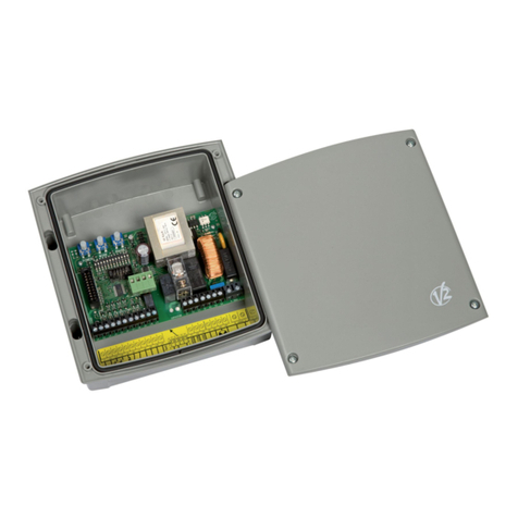
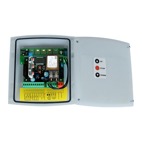
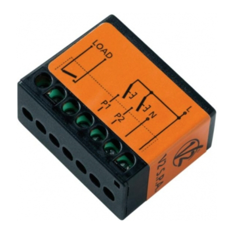
V2 EASY-TOP Series User manual

EASY-TOP
L n. 312
ED Z. 31/07/2014
V2 S.p.A.
Corso Principi di Piemonte, 65/67
12035 RACCON G (CN) TALY
tel. +39 01 72 81 24 11 - fax +39 01 72 84 050
[email protected] - www.v2home.com
CENTRA E DI COMANDO DITA E
PER SERRANDE AVVO GIBI I
DIGITA CONTRO UNIT FOR
RO ER SHUTTERS
ARMOIRE DE COMMANDE DIGITA E
POUR STORES
CUADRO DE MANIOBRAS DIGITA
PARA PERSIANAS ENRO AB ES
QUADRO E ÉCTRICO DIGITA
PARA ESTORES DE ENRO AR
DIGITA STEUERUNG FÜR RO TORE
DIGITA E STUURCENTRA E VOOR RO UIKEN
I
GB
F
E
P
D
N


ITA IANO
AVVERTENZE IMPORTANTI
Per chiarimenti tecnici o problemi di installazione contatta il
Servizio Clienti V2 al Numero Verde 800-134908 attivo dal
lunedì al venerdì dalle 8:30 alle 12:30 e dalle 14:00 alle 18:00
V2 S.p.A. si riserva il diritto di apportare eventuali
modifiche al prodotto senza preavviso; inoltre declina ogni
responsabilità per danni a persone o cose dovuti ad un uso
improprio o ad un’errata installazione.
meggere attentamente il seguente manuale di
istruzioni prima di procedere con l'installazione e la
programmazione della centrale di comando.
•l presente manuale di istruzioni è destinato solamente a
personale tecnico qualificato nel campo delle installazioni di
automazioni.
• Nessuna delle informazioni contenute all'interno del manuale
può essere interessante o utile per l'utilizzatore finale.
• Qualsiasi operazione di manutenzione o di programmazione
deve essere eseguita esclusivamente da personale qualificato.
’AUTOMAZIONE DEVE ESSERE REA IZZATA IN
CONFORMITÀ VIGENTI NORMATIVE EUROPEE:
EN 60204-1 (Sicurezza del macchinario, equipaggiamento
elettrico delle macchine, parte 1: regole generali).
EN 12445 (Sicurezza nell'uso di chiusure automatizzate,
metodi di prova).
EN 12453 (Sicurezza nell'uso di chiusure automatizzate,
requisiti).
• L'installatore deve provvedere all'installazione di un
dispositivo (es. interruttore magnetotermico) che assicuri il
sezionamento onnipolare del sistema dalla rete di
alimentazione. La normativa richiede una separazione dei
contatti di almeno 3 mm in ciascun polo (EN 60335-1).
• Una volta effettuati i collegamenti sulla morsettiera, è
necessario mettere delle fascette rispettivamente sui
conduttori a tensione di rete in prossimità della morsettiera
e sui conduttori per i collegamenti delle parti esterne
(accessori). n tal modo, nel caso di un distacco accidentale
di un conduttore, si evita che le parti a tensione di rete
possano andare in contatto con parti a bassissima tensione
di sicurezza.
• Per la connessione di tubi rigidi e flessibili o passacavi utilizzare
raccordi conformi al grado di protezione P55 o superiore.
• L’installazione richiede competenze in campo elettrico e
meccanico; deve essere eseguita solamente da personale
qualificato in grado di rilasciare la dichiarazione di conformità
di tipo A sull’installazione completa (Direttiva macchine
89/392 CEE, allegato A).
• E’ obbligo attenersi alle seguenti norme per chiusure
veicolari automatizzate: EN 12453, EN 12445, EN 12978
ed alle eventuali prescrizioni nazionali.
• Anche l’impianto elettrico a monte dell’automazione deve
rispondere alle vigenti normative ed essere eseguito a
regola d’arte.
• La regolazione della forza di spinta dell’anta deve essere
misurata con apposito strumento e regolata in accordo ai
valori massimi ammessi dalla normativa EN 12453.
• Collegare il conduttore di terra dei motori all'impianto di
messa a terra della rete di alimentazione.
• Osservare le necessarie precauzioni (esempio bracciale
antistatico) nel maneggiare le parti sensibili alle scariche
elettrostatiche.
DICHIARAZIONE DI CONFORMITÀ
V2 S.p.A. dichiara che i prodotti EASY-TOP sono conformi ai
requisiti essenziali fissati dalle seguenti direttive:
-2004/108/CEE (Direttiva EMC secondo le norme EN 55014-1,
EN 55014-2, EN 61000-3-2, 61000-3-3)
- 2006/95/CEE (Direttiva Bassa Tensione secondo le norme
EN 60335-1 + EN 60335-2-95 + EN 60335-2-97)
- ROHS2 2011/65/CE
Racconigi, lì 28/01/2014
l rappresentante legale della V2 S.p.A.
Cosimo De Falco
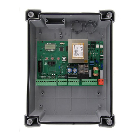
DESCRIZIONE DE A CENTRA E
La centrale EASY-TOP è un innovativo prodotto V2 che garantisce
sicurezza ed affidabilità per l'automazione di serrande avvolgibili.
• Uscita 230 Vac per 1 motore monofase
• Uscita 230 Vac per lampeggiante o luce di cortesia
temporizzabile
• Connettore rapido per l’inserimento di un ricevitore della
serie MR
• ngresso per selettore chiave o pulsante (START)
• ngressi per comandi separati SAL /SCEND (UP/DOWN)
• ngresso per pulsante di sicurezza (STOP)
• ngresso per fotocellula di sicurezza con test automatico di
funzionamento (PHOTO)
• ngresso per costa sensibile di sicurezza (EDGE):
possibilità di collegare una costa meccanica o resistiva con test
automatico di funzionamento oppure una costa ottica con
alimentazione in corrente continua a 30V e regolazione della
potenza del trasmettitore
• ngressi per finecorsa (FCA-FCC) utilizzabili in alternativa degli
ingressi EDGE e F RE
• ngresso per emergenza incendio o antifurto (F RE)
• Monitoraggio degli ingressi tramite display
• Logica di funzionamento e tempi di lavoro programmabili
tramite tasti e display
• Possibilità di funzionamento in modalità UOMO PRESENTE
CARATTERISTICHE
TECNICHE Modelli 230V Modelli 120V
Alimentazione 230V / 50Hz 120V / 60Hz
Carico max motore 1100W 600W
Carico max accessori
alimentati a 30 Vdc 3W 3W
Temperatura di lavoro -20 ÷ +60 °C -20 ÷ +60 °C
Fusibili di protezione F1 = 5A delayed F1 = 5A delayed
Dimensioni 170 x 185 x 70 mm
Peso 800 g
Protezione P55
1

ITA IANO
CO EGAMENTI E ETTRICI
mATTENZIONE: Gli ingressi normalmente chiusi STOP ( 2), FOTOCE U A ( 5), COSTA ( 6), FIRE ( 7), se non sono utilizzati
devono essere ponticellati con il COMUNE ( 3 - 8)
2

ITA IANO
3
1 START/UP. Contatto N.A.
2 STOP. Contatto N.C.
3 COMUNE (-)
4 DOWN. Contatto N.A.
5 FOTOCELLULA. Contatto N.C.
6
EDGE. Contatto N.C.
(costa di sicurezza - parametro in5 = oFF )
FCA Contatto N.C.
(finecorsa di apertura - parametro in5 = on)
7
F RE. Contatto N.C.
(allarme - parametro in5 = oFF )
FCC Contatto N.C.
(finecorsa di chiusura - parametro in5 = on)
8 COMUNE (-)
9 Regolazione potenza per costa ottica
10 Uscita alimentazione 30Vdc per fotocellule ed altri
accessori
11 30Vdc per alimentazione TX fotocellule per test
funzionale
E1 - E2
Lampeggiante 230Vac / 120Vac
(parametro ou1 = oFF)
Luce di cortesia 230Vac / 120Vac
(parametro ou1 = on)
E3 Apertura motore
E4 Comune motore
E5 Chiusura motore
NNeutro alimentazione 230Vac / 120Vac
Fase alimentazione 230Vac / 120Vac
A1 Schermatura antenna
A2 Centrale antenna
INSTA AZIONE DE A COSTA OTTICA
La centrale EASY-TOP è predisposta per l'installazione di una
costa ottica con alimentazione in corrente continua a 24V e
regolazione della potenza del trasmettitore.
Collegare il trasmettitore e il ricevitore secondo la seguente
tabella.
Dopo aver effettuato i collegamenti, alimentare la centrale e
regolare la potenza con il trimmer TR1 presente sulla centrale fino
ad ottenere il funzionamento ottimale della costa.
INGRESSO FIRE / A ARM
ngresso di sicurezza per il collegamento di un allarme
antincendio o di altro tipo che richiede l’apertura automatica
immediata della porta.
l comando F RE / ALLARM deve essere collegato tra il morsetto
F RE ( 7) e il COMUNE ( 8).
Quando si apre il contatto F RE la porta viene aperta e non può
essere richiusa fino a quando il contatto non viene ripristinato.
NOTA: se l’ingresso è impostato come allarme (in 4 = oFF),
quando il contatto F RE è aperto la porta non può essere aperta.
Se la porta è già aperta viene richiusa.
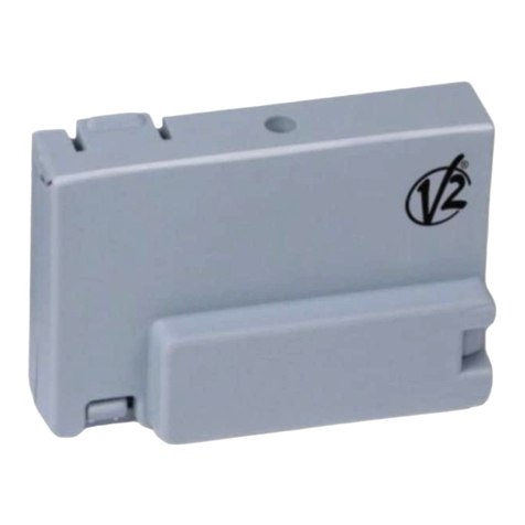
RICEVITORE AD INNESTO
La centrale è predisposta per l'innesto di un ricevitore della serie
MR.
l modulo ricevitore MR ha a disposizione 4 canali ad ognuno dei
quali è associato un comando della centrale:
• CANALE 1 gSTART/UP
• CANALE 2 gSTOP
• CANALE 3 gDOWN
• CANALE 4 gLUC D CORTES A
mATTENZIONE: Per la programmazione dei 4 canali e
delle logiche di funzionamento leggere attentamente le
istruzioni allegate al ricevitore MR.
TRASMETTITORE RICEVITORE
6 CAVO NERO
8 CAVO BLU CAVO BLU
9CAVO NERO
10 CAVO MARRONE
11 CAVO MARRONE

ITA IANO
4
FUNZIONAMENTO CON TIMER
La centrale permette il collegamento di un timer per
programmare gli orari di apertura e chiusura della porta.
Per utilizzare questa funzione è necessario impostare la
funzione Lo 3 (vedi TABE A FUNZIONI) su OGICA
AUTOMATICA (on) e la funzione Lo 5 su TIMER (oFF)
l timer deve essere collegato tra il morsetto di START ( 1) e il
COMUNE ( 3).
Ogni volta che il timer chiude il contatto L1-L3 l’automazione va
in apertura e resta in pausa fino a quando il contatto non viene
rilasciato.
A questo punto inizia il conteggio del tempo di pausa impostato,
dopo il quale l’automazione va in chiusura.
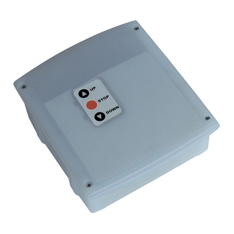
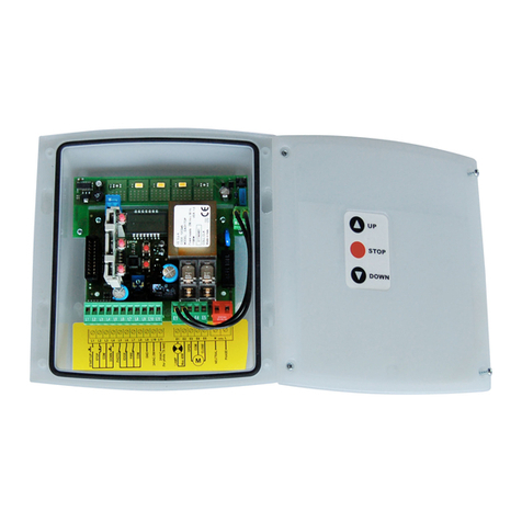
CONTENITORE CON PU SANTIERA
Le centrali EASY-TOP possono essere installate nel contenitore
con pulsantiera esterna (accessori cod. 171224 + 171226).
Per utilizzare i pulsanti è necessario installare l’adattatore 171226
come da figura.
n alternativa si può installare l’accessorio
WES-EASY (cod. 35B025), che oltre all’utilizzo della pulsantiera
permette il controllo delle coste via radio tramite gli appositi
sensori (vedi istruzioni WES-EASY).
pulsanti funzionano in parallelo ai comandi sulla morsettiera.
Questi rimangono tutti attivi compreso il comando di STOP, che
se non utilizzato, deve essere ponticellato con il comune.
Le versioni dotate di pulsantiera consentono inoltre di attivare
l’automazione in modalità UOMO PRESENTE in caso di
malfunzionamento dei dispositivi di sicurezza.
Tenendo premuto il tasto della pulsantiera, dopo 5 secondi viene
attivata l’automazione ignorando i dispositivi di sicurezza; il
motore si ferma immediatamente appena si rilascia il pulsante.
NOTA: questa funzione è disponibile anche da morsettiera
se la funzione Lo 5 è impostata su EMERGENZA
MONTAGGIO DEI PASSACAVI
l contenitore è predisposto per il montaggio di 4 passacavi nelle
apposite sedi con prerottura. l tipo di passacavi è indicato in
figura.
mATTENZIONE:
• Prima di forare il contenitore smontare la scheda elettronica.
• Forare il contenitore con una fresa adeguata rispetto alle
dimensioni del passacavo.
• Fissare i passacavi con gli apposidi dadi.

ITA IANO
5
PANNE O DI CONTRO O
Quando viene attivata l'alimentazione, la centrale verifica il
corretto funzionamento del display accendendo tutti i segmenti
per 1,5 sec. 8.8.8.8. Nei successivi 1,5 sec. viene visualizzata
la versione del firmware, ad esempio Pr 1 .0.
Al termine di questo test viene visualizzato il pannello di
controllo:
l pannello di controllo (in stand-by) indica lo stato fisico dei
contatti alla morsettiera e dei tasti di programmazione: se è
acceso il segmento verticale in alto, il contatto è chiuso; se è
acceso il segmento verticale in basso, il contatto è aperto.
Le frecce a sinistra del display indicano lo stato dei pulsanti MENU
e SEL.
Le frecce a destra del display indicano lo stato della serranda.
• La freccia più in alto si accende quando la serranda è in fase di
apertura.
• La freccia centrale indica che la serranda è in pausa.
Se lampeggia significa che è attivo il conteggio del tempo per
la chiusura automatica.
• La freccia più in basso si accende quando la serranda è in fase
di chiusura.
PROGRAMMAZIONE
La programmazione delle funzioni e dei tempi della centrale viene
eseguita tramite dei menù di configurazione, accessibili ed
esplorabili tramite i 2 tasti MENU e SEL.
• Per accedere al menù di programmazione premere il tasto
MENU fino a quando il display visualizza in 1
• Per modificare il valore di questo parametro premere il tasto
MENU: il display visualizza il valore attualmente impostato
(on / oFF)
•Selezionare il valore desiderato tramite il tasto SEL e premere
MENU per salvare il nuovo valore: il display visualizza
nuovamente in 1
• Premere il tasto SEL per selezionare gli altri parametri da
modificare
Tramite i tasti MENU e SEL selezionare e modificare i parametri
necessari: nelle prossime pagine è disponibile una tabella con tutti
i parametri di programmazione, i valori selezionabili, i valori
impostati di DEFAULT e una breve descrizione della
funzione.
Per uscire dal menù di programmazione tenere premuto il
tasto MENU fino a quando il display visualizza il pannello di
controllo.
Se non si preme nessun tasto per 30 secondi la centrale esce
dalla programmazione memorizzando i nuovi parametri.
Per uscire dal menù di programmazione e annullare le
modifiche fatte durante l’attuale sessione di programmazione,
premere contemporaneamente i tasti MENU e SEL fino a quando
il display visualizza il pannello di controllo.
Per caricare i dati di DEFA U T, quando la centrale NON è in
programmazione, premere contemporaneamente i tasti MENU e
SEL fino a quando il display visualizza dEF.
Con il tasto SEL selezionare il default che si desidera caricare e
premere MENU per confermare.
NOTA: la centrale viene fornita con la configurazione dEF1
impostata

ITA IANO
6
DISP AY oFF on dEF1 dEF2 dEF3
in 1 FOTOCE U A ATTIVA SO O IN CHIUSURA
L’intervento della fotocellula durante la fase di
apertura viene ignorato.
L’intervento della fotocellula durante la fase di
chiusura provoca la riapertura della serranda.
FOTOCE U A ATTIVA IN APERTUTA E
CHIUSURA
L’intervento della fotocellula durante la fase di
apertura causa l’arresto del motore.
Quando il raggio della fotocellula viene liberato,
l’automazione va in apertura per il tempo di
lavoro impostato nel parametro t i1 .
L’intervento della fotocellula durante la fase di
chiusura provoca la riapertura della serranda.
on oFF oFF
in 2 TEST FOTOCE U A NON ATTIVO
Non viene eseguito il test di funzionamento della
fotocellula
TEST FOTOCE U A ATTIVO
l TEST FOTOCELLULA verifica il corretto
funzionamento della fotocellula ogni volta che la
centrale riceve un comando di apertura o
chiusura.
Se il test fallisce il display visualizza - L5 -
oFF oFF oFF
in 3 COSTA DI SICUREZZA MECCANICA
L’ingresso L6 è configurato per gestire una costa
di sicurezza meccanica
COSTA DI SICUREZZA RESISTIVA / OTTICA
L’ingresso L6 è configurato per gestire una costa
di sicurezza resistiva / ottica con test di
funzionamento attivo.
Se il test fallisce il display visualizza - L6 -
oFF on oFF
in 4 FUNZIONE FIRE
L’ingresso L7 è configurato per gestire un allarme
antincendio
FUNZIONE A ARM
L’ingresso L7 è configurato per gestire un
comando antifurto
oFF oFF oFF
in 5 FUNZIONE EDGE / FIRE
L’ingresso L6 è configurato per gestire una costa
di sicurezza
L’ingresso L7 è configurato per gestire un allarme
FUNZIONE FINECORSA
L’ingresso L6 è configurato per gestire un
finecorsa di apertura
L’ingresso L7 è configurato per gestire un
finecorsa di chiusura
NOTA: se in5 è impostato su on le
impostazioni delle funzioni in3 e in4 non
vengono considerate
oFF oFF oFF
ou 1 AMPEGGIANTE
L'uscita (E1 - E2) viene attivata a intermittenza
(2 Hz) durante le fasi di apertura / chiusura e
durante la pausa se è attiva la richiusura
automatica
UCE DI CORTESIA
L'uscita (E1 - E2) viene attivata fissa durante le
fasi di apertura, pausa e chiusura. Terminato il
ciclo di funzionamento la luce rimane accesa
ancora per il tempo R TARDO SPEGN MENTO
LUC D CORTES A
oFF on on
ou 2 SEGNA AZIONE DI FINE CIC O NON ATTIVA
Al termine del ciclo di funzionamento la centrale
non invia alcuna segnalazione
SEGNA AZIONE DI FINE CIC O ATTIVA
Al termine del ciclo di funzionamento la centrale
invia un segnale ai sensori WES per l’attivazione
della modalità ENERGY SAV NG
oFF on oFF
Lo 1 OGICA START/STOP
L'ingresso START/UP comanda il ciclo di
funzionamento PASSO-PASSO o AUTOMAT CO in
base alla logica di funzionamento programmata.
L'ingresso DOWN non è attivo
OGICA UP/DOWN
L'ingresso START/UP comanda sempre l'apertura
e l'ingresso DOWN comanda sempre la chiusura,
indipendentemente dalla logica di
funzionamento programmata.
UP + DOWN premuti contemporaneamente
equivalgono ad un comando di STOP
oFF on on
Lo 2 START NON ATTIVO IN APERTURA
l comando di START durante la fase di apertura
viene ignorato
START ATTIVO IN APERTURA
l comando di START durante la fase di apertura
interrompe l'apertura (non viene caricato
l'eventuale timer per la richiusura automatica)
on on on
Lo 3 OGICA PASSO-PASSO
l comando di start attiva un ciclo di
funzionamento APRE-STOP-CH UDE-STOP-
APRE...
OGICA AUTOMATICA
l comando di start attiva un ciclo di
funzionamento APRE-PAUSA-CH UDE-STOP
La chiusura inizia automaticamente dopo il
tempo di pausa impostato
oFF oFF oFF

ITA IANO
7
DISP AY oFF on dEF1 dEF2 dEF3
Lo 4 OGICA UOMO PRESENTE
NON ATTIVA
L’utilizzatore può attivare l’automazione in
apertura o chiusura con un semplice
comando di start.
La durata massima dell’apertura o della chiusura
dipende dal tempo di lavoro
impostato.
OGICA UOMO PRESENTE ATTIVA
L'utilizzatore deve tenere premuto il pulsante di
START per tutta la durata dell'apertura o della
chiusura che si desidera effettuare.
La durata massima dell’apertura o della chiusura
dipende dal tempo di lavoro impostato.
La logica UOMO PRESENTE può essere attivata
sia con logica START/STOP che UP/DOWN.
l comando di STOP interrompe il ciclo di
funzionamento, indipendentemente dallo stato
degli ingressi di comando. Quindi se il tasto UP o
DOWN è premuto, l'intervento dello STOP ferma
il moto e al suo rilascio il motore NON S
MUOVE F NO A QUANDO L' NGRESSO UP o
DOWN NON V ENE R LASC ATO E
NUOVAMENTE PREMUTO
ATTENZIONE: quando viene abilitata la
funzione Uomo-Presente viene inibito il
funzionamento via radio. Per attivare il
funzionamento via radio impostare il
parametro Lo7 = on
oFF oFF on
Lo 5 FUNZIONE TIMER
Ogni volta che il timer chiude il contatto L1-L3
l’automazione va in apertura e resta in pausa
fino a quando il contatto non viene rilasciato.
FUNZIONE UOMO PRESENTE DI EMERGENZA
Se un comando viene rifiutato a causa di una
sicurezza attiva, mantenendo il comando attivo
per 5 secondi, la centrale attiva la modalità
uomo presente, e la serranda si muove fintanto
che il comando viene mantenuto.
Quando il comando viene sospeso la centrale
ritorna alla modalità impostata.
n questo modo è possibile muovere la serranda
quando si ha l’evidenza di un guasto su una
sicurezza.
oFF oFF oFF
Lo 6 ’INTERVENTO DE A COSTA DI SICUREZZA
NON DISABI ITA A CHIUSURA
AUTOMATICA
’INTERVENTO DE A COSTA DI SICUREZZA
DISABI ITA A CHIUSURA AUTOMATICA
on oFF oFF
Lo 7 OGICA UOMO PRESENTE DA PU SANTE
La logica uomo presente può essere attivata solo
tramite i pulsanti (morsettiera e pulsantiera).
OGICA UOMO PRESENTE DA PU SANTE E
DA TRASMETTITORE
La logica uomo presente può essere attivata
tramite i pulsanti (morsettiera e pulsantiera) e da
trasmettitore
oFF oFF on
Lo 8 OGICA UOMO PRESENTE ATTIVA IN
APERTURA E CHIUSURA
OGICA UOMO PRESENTE ATTIVA SO O IN
CHIUSURA
oFF oFF on
Lo 9 PRE AMPEGGIO NON ATTIVO PRE AMPEGGIO ATTIVO
Prima di attivare il motore in apertura il
lampeggiante viene acceso per 1 secondo.
Prima di attivare il motore in chiusura il
lampeggiante viene acceso per 3 secondo.
oFF oFF oFF
DISP AY FUNZIONE VA ORI DISPONIBI I dEF1 dEF2 dEF3
t i 1 TEMPO DI AVORO 7” - 1 0” - 1 5” - 20” - 30” - 45” - 60”
75” - 90” - 1 20”
20” 30” 30”
t i 2 TEMPO DI PAUSA 1 0” - 1 5” - 20” - 30” - 45” - 60”
90” - 1 20” - 1 80” - 250”
30” 1 5” 1 5”
t i 3 RITARDO SPEGNIMENTO UCI DI CORTESIA 3” - 5” - 1 0” - 20” - 30” - 60”
1 20” - 300” - 600” - 1 200”
3” 1 20” 1 20”

ITA IANO
8

ENG ISH
9
IMPORTANT REMARKS
For any installation problem please contact our Customer Service
at the number +39-0172.812411 operating Monday to Friday
from 8:30 to 12:30 and from 14:00 to 18:00.
V2 has the right to modify the product without previous notice;
it also declines any responsibility to damage or injury to people
or things caused by improper use or wrong installation.
m Please read this instruction manual very carefully before
installing and programming your control unit.
• This instruction manual is only for qualified technicians, who
specialize in installations and automations.
• The contents of this instruction manual do not concern the
end user.
• Every programming and/or every maintenance service should
be done only by qualified technicians.
AUTOMATION MUST BE IMP EMENTED IN COMP IANCE
WITH THE EUROPEAN REGU ATIONS IN FORCE:
EN 60204-1 (Machinery safety. electrical equipment
of machines, part 1: general rules)
EN 12445 (Safe use of automated locking
devices, test methods)
EN 12453 (Safe use of automated locking
devices, requirements)
• The installer must provide for a device (es. magnetotermical
switch) ensuring the omnipolar sectioning of the equipment
from the power supply. The standards require a separation of
the contacts of at least 3 mm in each pole (EN 60335-1).
• After making connections on the terminal board, use one
hose clamp to fix dangerous voltage wires near the terminal
board and another hose clamp to fix safety low voltage wires
used for accessories connection; this way, in case of accidental
detachment of a conducting wire, dangerous voltage parts
will not come into contact with safety low voltage ones.
• The plastic case has an P55 insulation; to connect flexible or
rigid pipes, use pipefittings having the same insulation level.
• nstallation requires mechanical and electrical skills, therefore
it shall be carried out by qualified personnel only, who can
issue the Compliance Certificate concerning the whole
installation (EEC Machine Directive 89/392, Annex A).
• The automated vehicular gates shall comply with the
following rules: EN 12453, EN 12445, EN 12978 as well as
any local rule in force.
• Also the automation upstream electric system shall comply
with the laws and rules in force and be carried out
workmanlike.
• The door thrust force adjustment shall be measured by means
of a proper tool and adjusted according to the max. limits,
which EN 12453 allows.
• Connect the earthing lead of the motors to the
electricity grid earth system.
• Observe all necessary precautions (e.g. anti-static
bracelet) for handling parts sensitive to
electrostatic discharges.
DEC ARATION OF CONFORMITY
V2 S.p.A. hereby declare that products EASY-TOP conform to the
essential requirements established in the following directives:
-2004/108/CEE (EMC Directive in accordance with standards
EN 55014-1, EN 55014-2, EN 61000-3-2, 61000-3-3)
- 2006/95/CEE (Low Voltage Directive in accordance with
standards EN 60335-1 + EN 60335-2-103)
- ROHS2 2011/65/CE
Racconigi, lì 28/01/2014
V2 S.p.A. legal representative.egale della V2 S.p.A.
Cosimo De Falco
DESCRIPTION OF THE CONTRO UNIT
The EASY-TOP digital control unit is an innovative V2 product
that guarantees safety and reliability for the automation of roller
shutters.
• 230 Vac output for 1 single-phase motor
• 230 Vac output for flashing light or timed courtesy light
• Plug-in adaptor for modular radio receiver MR2
• nput for key switch or pushbutton (START)
• nput for separate UP/DOWN commands
• nput for safety pushbutton (STOP)
• nput for safety photocell with automatic operating test
(PHOTO)
• Sensitive edge safety input (EDGE): can connect to a
mechanical or resistive rubber edge with automatic operation
test or to an optical edge with 30V DC power supply and by
adjusting the transmitter power
• nputs for limit switches (FCA-FCC) that can be used as an
alternative to the EDGE and F RE inputs
• nput for fire emergency or theft (F RE)
• Monitoring of the inputs on the display
• Logic of operation and programmable work times using the
keyboard and display
• Possibility of operating in DEAD MAN mode
TECHNICA
SPECIFICATIONS 230V models 120V models
Power supply 230V / 50Hz 120V / 60Hz
Max motor load 1100W 600W
Max accessories load
30 Vdc 3W 3W
Working temperature -20 ÷ +60 °C -20 ÷ +60 °C
Protection fuse F1 = 5A delayed F1 = 5A delayed
Dimensions 170 x 185 x 70 mm
Weight 800 g
Protection P55

ENG ISH
10
EECTRIC CONNECTIONS
mWARNING: Normally closed inputs STOP ( 2), PHOTOCE ( 5), EDGE ( 6), FIRE ( 7), if not used must be bridged through
the COMMON terminal ( 3 - 8)

ENG ISH
11
1 START/UP. N.O. contact
2 STOP. N.C. contact
3 COMMON (-)
4 DOWN. N.O. contact
5 PHOTOCELL. N.C. contact
6
EDGE. N.C. contact
(Safety edge - parameter in5 = oFF)
FCA. N.C. contact
(Opening limit switch - parameter in5 = on)
7
F RE. N.C. contact
(Alarm - parameter in5 = oFF)
FCC. N.C. contact
(Closing limit switch - parameter in5 = on)
8 COMMON (-)
9 Adjustment of the power for OPT CAL SAFETY EDGE
10 30 Vdc power output for photocells and
other accessories
11 30 Vdc power supply for functional test
TX photocell
E1 - E2
Flashing light 230Vac / 120Vac
(parameter ou1 = oFF)
Courtesy light 230Vac / 120Vac
(parameter ou1 = on)
E3 Motor open
E4 Motor common
E5 Motor close
N230Vac / 120Vac power supply - neutral
230Vac / 120Vac power supply - phase
A1 Antenna shield
A2 Antenna
OPTICA EDGE INSTA ATION
The EASY-TOP main control unit is configured for the installation
of one 24 Vdc powered optical edge and transmitter power
regulation.
Connect the transmitter and receiver in accordance
with the following table.
After having made the connections, power-up the main control
unit and adjust the power using the trimmer TR1 located on the
control unit so as to obtain optimal edge operation.
FIRE / A ARM INPUT
Safety input for connecting a fire or other type of alarm requiring
the immediate automatic opening of the door.
The F RE command should be connected between the F RE (L7)
and COMMON (L8) terminals.
When the F RE contact is opened, the door is opened and cannot
be closed again until the contact is reset.
NOTE: f the input is set as an alarm (in4 = oFF), when the F RE
contact is open, the port cannot be opened. f the port is already
open, it is closed.
P UG IN RECEIVER
The control unit is suitable for plugging in a MR receiver.
MR module receiver is provided with 4 channels and each of
them is suitable for a command of the control unit:
• CHANNEL 1 gSTART/UP
• CHANNEL 2 gSTOP
• CHANNEL 3 gDOWN
• CHANNEL 4 gCOURTESY L GHT
mWARNING: Before programming 4 channels and
function logics read carefully the instructions of MR
TRANSMITTER RECEIVER
6 BLACK CABLE
8 BLUE CABLE BLUE CABLE
9BLACK CABLE
10 BROWN CABLE
11 BROWN CABLE

ENG ISH
12
OPERATION WITH A TIMER
The control unit allows the connection of a timer for
programming door opening and closing times.
To use this function, it is necessary to set the Lo 3 function
(see FUNCTION TAB E) on the AUTOMATIC OGIC (on) and
the Lo 5 function on the TIMER (oFF)
The timer should be connected between the START (L1) and
COMMON (L3) terminals.
Each time the timer closes the contact, the automation device
opens the door and remains paused until the contract is released.
At this point the countdown starts, for the length of the pause
time set, after which the automation device closes the door.
CASE WITH KEYPAD
The EASY-TOP control units may be installed in cases with
external keypads (accessory codes 171224 + 171226).
To use the keypad buttons, it is essential to install adapter
171226 as shown in the figure.
Alternatively, the WES-EASY accessory may be installed (code
35B025), which besides using the keypad allows controlling the
edges by radio using the special sensors (see the WES-EASY
instructions).
The keypad buttons operate in parallel with the terminal controls.
These all remain active,
including the STOP command, and must be jumpered to ground
if not used.
Versions supplied with keypads also allow the automation device
to operate in DEAD MAN mode should the safety devices
malfunction.
By pressing and holding the button on the keypad, the
automation device is activated after 5 seconds, overriding the
safety devices; the motor stops immediately as soon as the
button is released.
NOTE: This function is also available from the terminal
board if the Lo 5 function is set to EMERGENCY
CAB E G AND ASSEMB Y
The casing can accept 4 cable glands in the special easy-break
housings. The type of cable gland is indicated in the figure.
mP EASE NOTE:
• Remove the electronic circuit board before drill the casing.
• Drill the container using a suitably sized cutter, according to
the dimensions of the cable gland.
• Fix the cable glands using the special nuts.

ENG ISH
13
CONTRO PANE
When power is on, the control unit checks that display correctly
operates by switching on all segments for 1.5 sec. 8.8.8.8.
Firmware version, e.g. Pr 1 .0, will be viewed in the following
1.5 sec.
Panel will be viewed upon completion of this test.
The control panel represents the physical status of the
terminal board contacts and of the program mode keys: if the
upper vertical segment is on, the contact is closed; if the lower
vertical segment is on, the contact is open.
The arrows to the left of the display indicate the status of the
MENU and SEL buttons.
The arrows to the right of the display indicate the status of the
shutter.
• The highest arrow lights up when the shutter is in the
opening phase.
• The central arrow indicates that the shutter is paused.
f it flashes it means that the timer for automatic closing is
active.
• The lowest arrow lights up when the shutter is in the opening
phase.
PROGRAMMING
The functions of and times of the control unit are programmed
via the configuration menu, which can be accessed and explored
using the 2 MENU and SEL keys.
• To access the programming menu, press the MENU key until
the display shows in 1
• To change the value of this parameter, press the MENU key:
the display shows the currently set value (on / oFF)
• Select the desired value with the SEL key and press the MENU
button to save the new value: the display shows in 1 again
• Press the SEL key to select the other parameters to be changed
Using the MENU and SEL keys to select and change the required
parameters: in the following pages there is a table with all
programming parameters, values selected, DEFAULT values set
and a brief description of the function.
To exit the programming menu, press the MENU key until the
display shows the control panel
f no button is pressed for 30 seconds, the control unit exits
programming mode and stores the new parameters.
To exit the programming menu and undo the changes made
during the current programming session, press the MENU and
SEL keys simultaneously until the display shows the control panel.
To load default data, when the control unit is NOT in
programming mode, press the MENU and SEL keys
simultaneously until the display shows dEF.
With the SEL key, select the default that you want to load and
press MENU to confirm.
NOTE: the control unit is supplied with the dEF1 configuration
set

ENG ISH
14
DISP AY oFF on dEF1 dEF2 dEF3
in 1 PHOTOCE ACTIVE ON Y DURING C OSING
The intervention of the photocell during the
opening stage is ignored.
The intervention of the photocell during the
closing stage causes the shutter to reopen.
PHOTOCE ACTIVE DURING OPENING AND
C OSING
The intervention of the photocell during the
opening phase causes the motor to stop.
When the photocell beam is released, the
automation starts during opening for the work
time set in parameter t i1 .
The intervention of the photocell during the
closing stage causes the shutter to reopen.
on oFF oFF
in 2 PHOTOCE TEST INACTIVE
The photocell operation test is not
performed
PHOTOCE TEST ACTIVE
Each time the control unit receives an open or
close command, the PHOTOCELL TEST verifies
that the PHOTOCELL is operating correctly.
f the test fails, the display shows - L5 -
oFF oFF oFF
in 3 MECHANICA SAFETY EDGE
The L6 input is configured to manage a
mechanical safety edge
RESISTIVE RUBBER / OPTICA SAFETY EDGE
The L6 input is configured to manage a safety
edge (resistive rubber / optical) with active
operation test.
f the test fails, the display shows - L6 -
oFF on oFF
in 4 FIRE FUNCTION
The L7 input is configured to manage a fire
alarm
A ARM FUNCTION
The L7 input is configured to manage an
anti-theft command
oFF oFF oFF
in 5 EDGE / FIRE FUNCTION
The L6 input is configured to manage a safety
edge
The L7 input is configured to manage an alarm
IMIT SWITCH FUNCTION
The L6 input is configured to manage an
opening limit switch
The L6 input is configured to manage a closing
limit switch
NOTE: f in 5 is set on the settings of the in 3
and in 4 functions, they are not considered
oFF oFF oFF
ou 1 F ASHING IGHT
Output (E1 - E2) is on intermittently (2 Hz) during
opening and closing and during pause mode, if
automatic reclosing is active
COURTESY IGHT
The output (E1 - E2) is on and fixed during
opening, pause and closure. Having completed
the operating cycle, the light remains on for the
COURTESY L GHT OFF DELAY time
oFF on on
ou 2 END OF CYC E NON-ACTIVE SIGNA
At the end of the operating cycle, the control
unit sends no signal
END OF CYC E ACTIVE SIGNA
At the end of the operating cycle, the control
unit sends a signal to the WES sensors to activate
ENERGY SAV NG mode
oFF on oFF
Lo 1 START/STOP OGIC
The START/UP input controls the STEP or
AUTOMAT C operational cycle based on the
programmed operational logic.
The DOWN input is inactive
UP/DOWN OGIC
The START/UP input always controls opening
and the DOWN input always controls closing,
independently of the operational logic
programmed.
UP + DOWN when pressed simultaneously is the
same as a STOP command
oFF on on
Lo 2 START INACTIVE WHI E OPENING
During opening, the START command
is ignored
START ACTIVE WHI E OPENING
During opening, the START command
interrupts opening (no timer is set for automatic
re-closure)
on on on
Lo 3 STEP OGIC
The start command activates an
OPEN-STOP-CLOSE-STOP-OPEN
operational cycle
AUTOMATIC OGIC
The start command activates an
OPEN-PAUSE-CLOSE-STOP operational cycle
Closure starts automatically after the pause
time set
oFF oFF oFF

ENG ISH
15
DISP AY oFF on dEF1 dEF2 dEF3
Lo 4 DEAD MAN OGIC INACTIVE
By simply using the start command, the user can
activate the automation device in opening or
closing.
The maximum duration of opening or closing
depends on the operating time set
DEAD MAN OGIC ACTIVE
The user must press and hold the start button
for the entire duration of the desired opening or
closing procedure.
The maximum duration of opening or closing
depends on the operating time set.
DEAD MAN logic may be implemented with
both Start/Stop and Up/Down logic.
The STOP command interrupts the operational
cycle, independently of the status of the control
inputs.
Hence, if the UP or DOWN button is pressed, the
action of STOP is to stop motion, and on its
release the motor DOES NOT MOVE UNT L THE
UP or DOWN NPUT S RELEASED AND PRESSED
ONCE MORE
P EASE NOTE: when the Man-Present
function is enabled, radio-controlled
operation is disabled. To activate via radio,
set the parameter Lo 7 = on
oFF oFF on
Lo 5 TIMER FUNCTION
Each time the timer closes the contact L1-L3, the
automation starts during opening and remains
paused until the contact is released.
EMERGENCY DEAD-MAN FUNCTION
f a command is rejected because of active safety,
keep the command active for 5 seconds, the
control unit then activates dead-man mode, and
the shutter moves as long as the switch is held.
When the command is suspended, the control
unit returns to the mode set.
This way, it is possible to move the shutter when
there is evidence of a fault on a safety.
oFF oFF oFF
Lo 6 THE INTERVENTION OF THE SAFETY EDGE
DOES NOT DISAB E AUTOMATIC C OSING
THE INTERVENTION OF THE SAFETY
DISAB ES AUTOMATIC C OSING
on oFF oFF
Lo 7 DEAD MAN OGIC FROM BUTTON
The dead-man logic can only be activated via
buttons (terminal board and push button panel).
DEAD MAN OGIC FROM BUTTON AND
FROM THE TRANSMITTER
The dead-man logic can be activated via buttons
(terminal board and push button panel) and from
the transmitter.
oFF oFF on
Lo 8 DEAD MAN OGIC ACTIVATED DURING
OPENING AND C OSING
DEAD MAN OGIC ACTIVATED ON Y DURING
C OSING
oFF oFF on
Lo 9 PRE-F ASHING NOT ACTIVATED PRE-F ASHING ACTIVATED
Before activating the motor during opening, the
flashing light is turned on for 1 second.
Before activating the motor during closing, the
flashing light is turned on for 3 seconds.
oFF oFF oFF
DISP AY FUNCTION AVAI AB E VA UES dEF1 dEF2 dEF3
t i 1 WORK TIME 7” - 1 0” - 1 5” - 20” - 30” - 45” - 60”
75” - 90” - 1 20”
20” 30” 30”
t i 2 PAUSE TIME 1 0” - 1 5” - 20” - 30” - 45” - 60”
90” - 1 20” - 1 80” - 250”
30” 1 5” 1 5”
t i 3 DE AYED TURNING OFF OF THE COURTESY
IGHTS
3” - 5” - 1 0” - 20” - 30” - 60”
1 20” - 300” - 600” - 1 200”
3” 1 20” 1 20”

ENG ISH
16

FRANÇAIS
17
CONSEI S IMPORTANTS
Pour tout précision technique ou problème d’installation V2
dispose d’un Service Clients à Votre disposition du lundi au
vendredi de 8:30 à 12:30 et de 14:00 heures à 18:00 heures. au
numéro +39-0172.812411
V2 S.p.A. se réserve le droit d’apporter d’éventuelles
modifications au produit sans préavis; elle décline en outre
toute responsabilité pour tous types de dommages aux
personnes ou aux choses dus à une utilisation imporopre
ou à une mauvaise installation.
mAvant de proceder avec l'installation et la
programmation, lire attentivement les notices.
• Ce manuel d'instruction est destiné à des techniciens qualifiés
dans le domain des automatismes.
• Aucune des informations contenues dans ce livret pourra être
utile pour le particulier.
• Tous operations de maintenance ou programation doivent être
faites à travers de techniciens qualifiés.
’AUTOMATION DOIT ÊTRE RÉA ISÉE CONFORMÉMENT
AUX DISPOSITIFS NORMATIFS EUROPÉENS EN VIGUEUR
EN 60204-1: (Sécurité de la machinerie. Equipement
électriquedes machines, partie 1: régles générales).
EN 12445: (Sécurité dans l’utilisation de fermetures
automatisées, méthodes d'essai).
EN 12453: (Sécurité dans l'utilisation de fermetures
automatisées, conditions requises).
• L'installateur doit pourvoir à l'installation d'un dispositif
(ex. interrupteur magnétothermique) qui assure la coupure
omnipolaire de l'équipement du réseau d'alimentation.
La norme requiert une séparation des contacts
d'au moins 3 mm pour chaque pôle (EN 60335-1).
• Quand on a effectué les branchements à la borniere, il faut
mettre des bandes sur les conducteurs à tension qui se
trouvent en proximité de la borniere et sur les conducteurs
pour le branchement des parties externes (accessoires).
De cette maniere, en cas de détachement d'un conducteur, on
évite que les partie en tension puissent aller en contact avec
les parties à faible tension de sécurité.
• Pour la connexion de tubes rigides ou flexibles utiliser des
raccordements possédant le P55 niveau de protection.
• L’installation requiert des compétences en matière d’électricité
et mécaniques; doit être faite exclusivement par techniciens
qualifiés en mesure de délivrer l’attestation de conformité
pour l’installation (Directive 89/392 CEE, - A).
• l est obligatoire se conformer aux normes suivantes pour
fermetures véhiculaires automatisées: EN 12453, EN 12445,
EN 12978 et à toutes éventuelles prescriptions nationales.
• Même l’installation électrique ou on branche l’automatisme
doit répondre aux normesen vigueur et être fait à règles de
l’art.
• La régulation de la force de poussée du vantail doit être
mesurée avec outil spécial et réglée selon les valeurs maxi
admis par la norme EN 12453.
• Brancher le câble de terre des moteurs à l'installation de mise
à la terre du réseau d'alimentation.
• Précautions nécessaires à prendre (par exemple brassard
antistatique) pour manipuler les parties sensibles aux
décharges électrostatiques.
DÉC ARATION DE CONFORMITÉ
V2 S.p.A. déclare que les produits EASY-TOP sont conforment
aux qualités requises essentielles fixées par les directives
suivantes:
-2004/108/CEE (Directive EMC suivant les normes
EN 55014-1, EN 55014-2, EN 61000-3-2, 61000-3-3)
- 2006/95/CEE (Directive Basse tension suivant les normes
EN 60335-1 + EN 60335-2-103)
- ROHS2 2011/65/CE
Racconigi, 28/01/2014
Le représentant dûment habilité V2 S.p.A.
Cosimo De Falco
DESCRIPTION DE 'ARMOIRE DE
COMMANDE
L'armoire de commande numérique EASY est un novateur
produit V2 qui garantit une sécurité et une fiabilité pour
l'automatisation de store.
• Sortie 230 Vac pour 1 moteur monophasé
• Sortie 230 Vac pour clignotant ou lumière de courtoisie
temporisable
• Connecteur rapide pour récepteur embrochable MR
• Entrée pour sélecteur à clé ou bouton-poussoir (START)
• Entrées pour commandes séparées MONTÉE/DESCENTE
(UP/DOWN)
• Entrée pour bouton-poussoir de sécurité (STOP)
• Entrée pour cellule photo-électrique de sécurité avec test
automatique de fonctionnement (PHOTO)
• Entrée pour barre palpeuse de sécurité (EDGE) : possibilité de
connecter une barre palpeuse mécanique ou résistif avec test
automatique de fonctionnement ou bien une barre palpeuse
optique avec alimentation en courant continu à 30V et
régulation de la puissance du transmetteur
• Entrées de fin de course (FCA-FCC) utilisables comme
alternative aux entrées EDGE et F RE
• Entrée pour urgence incendie ou antivol (F RE)
• Monitorage des entrées par l'intermédiaire de l'écran
• Logique de fonctionnement et durées de fonctionnement
programmables par l'intermédiaire des touches et de l'écran
• Possibilité de fonctionnement en modalité HOMME MORT
CARACTÉRISTIQUES
TECHNIQUES Modèles 230V Modèles 120V
Alimentation 230V / 50Hz 120V / 60Hz
Charge max moteur 1100W 600W
Charge max accessoires
30 Vdc 3W 3W
Température de travail -20 ÷ +60 °C -20 ÷ +60 °C
Fusible de protection F1 = 5A delayed F1 = 5A delayed
Dimensions 170 x 185 x 70 mm
Poids 800 g
Protection P55

FRANÇAIS
18
BRANCHEMENTS E ECTRIQUES
mIMPORTANT: es entrées normalement fermées STOP ( 2), PHOTOCE U E ( 5), BARRE PA PEUSE ( 6), FIRE ( 7), si elles ne
sont pas utilisées doivent être raccordées par pontage au câble COMMUN ( 3 - 8)
Table of contents
Languages:
Other V2 Control Unit manuals