CRE GENSYS COMPACT MAINS Guide


TECHNICAL DOCUMENTATION
2
A56_MAINS_A90020-L-E
Table of contents
Description .................................................................................................................................... 4
Front Face ............................................................................................................................................... 4
Rear Face ................................................................................................................................................ 6
Panel Mounting ......................................................................................................................................... 7
UL Requirements ...................................................................................................................................... 9
Usage ................................................................................................................................................... 11
Password ............................................................................................................................................... 11
LCD ....................................................................................................................................................... 12
Wiring .................................................................................................................................................... 14
Digital Inputs ......................................................................................................................................... 19
Digital Outputs and Output Relays ........................................................................................................... 21
Analog Inputs ......................................................................................................................................... 22
Hysteresis DI ......................................................................................................................................... 27
Hysteresis AI .......................................................................................................................................... 28
Settings ......................................................................................................................................... 29
Engine ................................................................................................................................................... 29
Speed/Voltage Control ............................................................................................................................ 33
Circuit Breakers ...................................................................................................................................... 36
Synchronization ...................................................................................................................................... 40
Load/Unload Ramp ................................................................................................................................. 44
kW/kVAR regulation ................................................................................................................................ 45
Protections ............................................................................................................................................. 46
Events ................................................................................................................................................... 49
Control Loop PID .................................................................................................................................... 50
Advanced Settings ................................................................................................................ 51
Droop .................................................................................................................................................... 51
Static Paralleling ..................................................................................................................................... 52
Load Shedding ........................................................................................................................................ 54
Maintenance Schedule ............................................................................................................................ 56
Synch & Load Share only ......................................................................................................................... 57
Mains application ................................................................................................................. 59
Change-over mode .................................................................................................................................. 59
No break Change-over ............................................................................................................................. 62
Permanent ............................................................................................................................................. 66
Advanced Functions ........................................................................................................... 69
Easy Flex® ............................................................................................................................................ 69
User variables ........................................................................................................................................ 75
Alternative selection ............................................................................................................................... 76
Scheduler ............................................................................................................................................... 78
Modbus TCP Mapping .............................................................................................................................. 80
Logger ................................................................................................................................................... 81
Communications ...................................................................................................................... 82
Network ................................................................................................................................................. 82
Modbus TCP/IP ....................................................................................................................................... 84
CANopen ................................................................................................................................................ 87
SAE J1939 .............................................................................................................................................. 89
J1939 custom frames settings ................................................................................................................. 93
J1939 sniffer ........................................................................................................................................... 96
MTU MDEC ............................................................................................................................................. 97
Modbus client ....................................................................................................................................... 100

TECHNICAL DOCUMENTATION
3
A56_MAINS_A90020-L-E
CAN bus Good Practices ........................................................................................................................ 103
Appendices ................................................................................................................................ 105
ECU J1939 ............................................................................................................................................ 105
Short Circuit Protection ......................................................................................................................... 113
Troubleshooting .................................................................................................................................... 120
Standards for Generator ........................................................................................................................ 124
Certifications ........................................................................................................................................ 125
Software Variables ................................................................................................................................ 126

TECHNICAL DOCUMENTATION
4
A56_MAINS_A90020-L-E
Description
Front Face
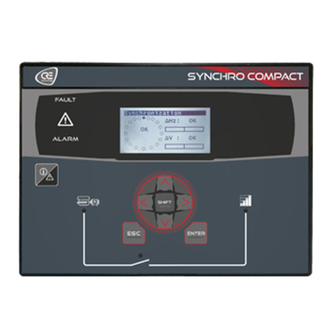
GENSYS COMPACT Mains
PIN Buttons Functions
1 SHIFT button Additional functions.
2 RIGHT button Navigation button (Right).
3 DOWN button Navigation button (Down).
4 LEFT button Navigation button (Left).
5 UP button Navigation button (Up).
6 ENTER button Validating entry / MENU.
7 ESC button Cancel entry / escape MENU.
8 INFO button Allows access to the active faults, active alarms, events history or information
pages.
9(1) Generator circuit breaker button
Can only be used in MAN mode.
Generator circuit breaker control.
Press to Open. Press to Close (synchronization & load transfer will be done
automaticallyif Bus is powered & configuration is setup for paralleling operation).
10(1) Mains circuit breaker button
Can only be used in MAN mode.
Mains circuit breaker control.
Press to Open. Press to Close (synchronization & load transfer will be done
automatically if Bus is powered & configuration is setup for paralleling operation).
11(1) STOP button
Can only be used in MAN mode.
Stop the Generator.
Pressing once this button will set the Generator offload and initiate cooling down
sequence.
12(1) START button Can only be used in MAN mode.
Start the Generator.
13(1) MAN button MAN mode.
The associated LED lights up when the mode is activated.
14(1) TEST button TEST mode.
The associated LED lights up if the mode is activated.

TECHNICAL DOCUMENTATION
5
A56_MAINS_A90020-L-E
PIN Buttons Functions
15(1) AUTO button AUTO mode.
The associated LED lights up when the mode is activated.
16 ALARMindicator The LED flashes when an alarm appears.
The LED is lit when an alarm is acknowledged, but not reseted.
17 DEFAULT indicator The LED flashes when a Fault occurs.
The LED is lit when a Fault is acknowledged, but not reseted.
18 LCD display Screen size: 40mm x 70mm; Back-light : typical 50cd/m2, configurable. Type: STN;
64 x128 pixels.
(1) Not available according to controller type.
Note: Pressing the button STOP twice will set the Generator offload and stop the engine without cooling down sequence.
Navigation keys
Keys Navigation mode Edition mode
Scrolling menus/parameters Modifying parameters values once selected: When up/down
keys are used to modify values, holding the key will
accelerate the entry scrolling.
Right arrow:
- Accessing a menu.
- Navigating right in display/parameters pages
Left arrow:
- Return to previous menu.
- Navigating left in display/parameters pages.
NA
+ will increase/decrease the
brightness of the LCD display.
+ will increase/decrease the contrast
of the LCD display.
In MAN mode, when the Generator is offload, use
to increase/decrease:
§The speed when the "Speed governor control" page is
displayed.
§The voltage when the "AVR control" page is displayed.
Note: Available only on GENSYS COMPACT PRIME and
GENSYS COMPACT MAINS.
Return to previous menu. Cancel setting and return to Navigation mode.
Accessing a menu / Switching to Edition mode. Validation of the modified parameter and return to
Navigation mode.
Button inhibition
To inhibit front panel buttons, use the i4Gen Suite Software/Controller settings/System/Button inhibition page.
This page shows the list of front panel buttons, tick the corresponding box to inhibit actions on the button.
It is also possible to inhibit the buttons by Modbus by modifying the variable 3557. Each bit of the variable
corresponds to a button. To know the bit associated to each button, please refer to the image above. Ex : Bit number
6 will inhibit the "Enter" button, bit number 1 will inhibit the "Shift" button.
External button requests
It is possible to remotely activate button actions by Modbus TCP, for a remote manual control for example.
If a button action is controlled by Modbus TCP, the last request received (external or from the front panel) is treated
in priority and cancel the previous request.
MAN / AUTO: If the 2 modes are requested, the MAN mode request cancels the AUTO mode one.
The buttons on the front panel can be replaced by external commands via digital inputs.

TECHNICAL DOCUMENTATION
6
A56_MAINS_A90020-L-E
Rear Face
GENSYS COMPACT Mains
Simplified Wiring Diagram

TECHNICAL DOCUMENTATION
7
A56_MAINS_A90020-L-E
Panel Mounting
The unit is designed for panel mounting, which provides user with access only to the front panel.
WARNING
THE UNIT IS NOT GROUNDED
·Take all measures against Electronic Static Discharges.
·Do not try to open the unit.
Failure to follow these instructions may damage the unit.
Environmental requirements:
·Operating temperature: -20…70°C (-4...158°F); LCD display slows down a bit under -5°C (23°F). Avoid direct
exposure to the sun.
·Storage temperature: -40...70°C (-40...158°F).
·Altitude: ≤ 4000m (13123ft) for a maxAC voltage of 480VAC; ≤ 5000m (16404ft) for a maxAC voltage of
400VAC.
Unpacking
Make sure the packaging contains:
·The unit.
·6 connectors.
·1 fixing kit composed of 2 parts.
·4 screws.
·A delivery bill.
Unpack and keep the packaging in case of return.
Make sure the unit does not show scratches or visible defaults. Otherwise describe them on the RMA sheet
(available on CRE TECHNOLOGY website) and return it with the product to your distributor.

TECHNICAL DOCUMENTATION
8
A56_MAINS_A90020-L-E
Installation
Preparation
·Torque of mounting brackets: 0.4Nm.
·Cut out the panel to 220x160mm (8.7x6.3in) minimum.
·Make sure the cut-out is smooth and clean.
Mounting
0 Tool : cross-heas screwdriver size 1
1 Pass the unit through the mounting surface
2 In the rear, cover each of the four spacers
using the 2 parts of the fixing kit.
3 Screw a first corner against the mounting
surface
4 Repeat on the diagonally opposite spacer
5 Repeat on the other diagonal and tighten
equally (do not overtighten)

TECHNICAL DOCUMENTATION
9
A56_MAINS_A90020-L-E
UL Requirements
Skip this chapter if your application does not require to follow the UL specification.
Circuit separation
The communication, sensor, and/or battery derived circuit conductors shall be separated and secured to maintain at
least 1/4” (6mm) separation from the Generator and the Mains connected circuit conductors unless all conductors
are rated 600V or greater.
Other circuits ratings
For information on circuits ratings, see chapter Wiring.
Mains Ratings
Over-voltage Category
III, 300VAC system voltage.
Sensing Generator / Mains Voltage Measurement (J4)
300VAC max P-N, 2 phases; 500VAC P-P 3 phases, 35...75Hz.
Current Inputs (J5)
Must be connected through listed or recognized isolating current transformers with secondary rating of 5A max
50/60Hz. (XODW2.8) Instrument transformers (according to IEEE C57.13 series or the equivalent).
Communication Circuits
Must be connected to communication circuits of UL Listed equipment.
Output Pilot Duty (J3)
250VAC, 5A max general purpose, 240VAC, 1/4HP for NO contact, 1/6HP for NC contact Pilot duty: C150, C300.
Digital outputs (J1)
FET: Fuel shutoff: 63VA, 1.8A maxcurrent.
Overcurrent protection (DC supply and L1, L2, L3, N)
Installer shall protect DC supply and L1, L2, L3, N by fuse Type: R/C (JDYX2/7), or R/C (JDYX2) and CSA
Certified Class 1422-30.
Rating of fuses:
·DC supply to be protected by 5A, 40VDC max.
·L1, L2, L3, N, fuse protection 100mA/600VAC max.
Terminals Wiring
Terminal (screw type):
·Tightening Torque: 3.5lb.in (0.4Nm).
Wires :
·28-14 AWG, Cu, 75°C min.
Conductor protection must be provided in accordance with NFPA 70, Article 240.
Low voltage circuits (35VDC or less) must be supplied from the engine starting battery or an isolated secondary
circuit.
Environment
Device must be installed in an unventilated or filtered ventilation enclosure to maintain a pollution degree 2
environment.
Maximum surrounding air temperature rating: 45°C.
ADVANCED WIRING DIAGRAM
Wiring diagrams available on the website CRE TECHNOLOGY : GENSYS COMPACT MAINS HMI _ CORE -

TECHNICAL DOCUMENTATION
11
A56_MAINS_A90020-L-E
Usage
Password
Important information
Advice
·Adjustment tip
·Usage of the controller
Failure to comply with the following recommendations may cause malfunctions.
The menus will be automatically locked if no operation is performed during the time set in the i4Gen Suite
Software/Settings/System/Password menu (Factory setting: 30 minutes).
The standby screen will be displayed.
The module provides secured password access to protect configuration changes and limit data accessibility:
Level Default password Authorization Accessible pages and
items
0No password. Press By default, this level is not
password protected, but
you can implement one.
Supervision menu pages
only.
1 1 User level, settings and
commissioning. Supervision and
Settings menus pages.
2 1234 Used to change advanced
settings. Advanced settings
Passwords can be changed via CRE PC software: i4Gen Suite Software
To access the Supervision menu, press .
To access the Settings menus, the padlock must be released:
1. Press to select Settings.
2. Press to switch to password input mode (as for other settings).
3. Change the character by pressing
4. Move to the next character by pressing
5. Repeat the operation for each character.
6. Confirm the password by pressing

TECHNICAL DOCUMENTATION
12
A56_MAINS_A90020-L-E
LCD
Navigation
Press , then, select the required menu, then press and enter the level 1 password if necessary
(Settings):
A black pointer spots the currently selected item/setting.
Two main menus are available on the LCD screen and three in i4Gen Suite Software:
·Controller supervision gives all product measurements in real time.
·Controller settings is used to adjust the controller and system (date/time, screen features, ...) settings
·i4Gen Suite (only in i4Gen Suite Software is used to adjust i4Gen Suite settings.
To cycle through the menus and menu items, press or
To cycle through the pages of the actual menu, press or
Edition
To change a setting:
1. Navigate to the setting to be changed.
2. Press to switch to Edition mode; the current value blinks.
3. Press or to get the new value.
4. Press to validate the new value, to reject it. Module returns to Navigation mode.
It is also possible to change settings using Modbus TCP.
Dedicated pages
Dedicated pages include:
·Active fault: currently active or unacknowledged faults.
·Active alarm: currently active or unacknowledged alarms.
·History: a list of all alarms/faults/events that happened with their state and timestamp.
·Information pages.
Press to access the dedicated pages menu. It is then possible to navigate through these dedicated pages
using the arrow buttons.
To return to the previous page, press or .
EVENTS
Up to 15 active events and 30 archived events can be displayed on the screen.
Each event is time-stamped as follows:
jj/mm/yy hh:mn:ss protec. label On (or Off).
To reset events, press +

TECHNICAL DOCUMENTATION
13
A56_MAINS_A90020-L-E
Note: Correct the condition that triggered the protection before performing a reset; if necessary, the protection
will trip again.
Information
These pages allow to display the power and engine current state with the associate elapsed time in this state.
Power [4000] displays the unit current state regarding power management.
Engine [4001] displays the unit current state regarding the engine.
Information variables: to display any variable, enter the code of the variable to be displayed.

TECHNICAL DOCUMENTATION
14
A56_MAINS_A90020-L-E
Wiring
Tool: insulated screwdriver Ø2.5 mm (0.1 in), tightening torque: 0.8 Nm (7 lb-in) max.
Accessories: 4, 5, 6, 8, 15 & 18-terminal cable connectors, protective gloves, carpet if the floor is wet.
WARNING
THE UNIT IS NOT PROTECTED
·Use external fuses:
§Generator and Mains phases: 100mA/600VAC
§Battery positive: 5A/40VDC
·Install the fuses as near as possible to the unit, in a place easily accessible to the user.
Failure to follow these instructions may damage the unit.
DANGER
RISK OF ELECTRIC SHOCK, EXPLOSION OR ARCING
§The module may only be installed and maintained byqualified electricians.
§Use personal protective equipment (PPE)
§Follow good safety practices for electrical work.
§Turn off the power before installing or replacing a fuse, and before installing the module.
§Use equipment adapted to check the absence of voltage.
§Do not use a resettable fuse.
Failure to followthese recommendations mayresult in death or serious injury.
General procedure
1. Make sure the cable connectors are not plugged.
2. Take on protective gloves.
3. Connect the wires on each cable connector in accordance with the National Wiring Regulations.
4. Plug each cable connector onto the related connector.
5. Plug a direct Ethernet cord (RJ45, male-male, 100m max., 100W; a crossover cable such as 3-m longA53W1
is OK as long as your switch uses auto MDI/MDIX technology or if the link to PC is direct) and lock the rear
door.
Recommendations
Wires section: 2.5mm² (AWG13).
To avoid ElectroMagnetic Interferences, shield cables appropriately; for CAN bus, see CAN bus good practices.
Isolation : keep the power cable separate from the CAN bus cables. The latter can be installed in the same duct as
the low level I/O wires (under 10V DC).
If power and communication cables have to cross each other, do it at right angles to avoid crosstalk:
Wiring diagrams available on the website CRE TECHNOLOGY : GENSYS COMPACT MAINS HMI _ CORE -
Standard wiring schematics

TECHNICAL DOCUMENTATION
15
A56_MAINS_A90020-L-E
Upper blocks
DANGER
EXPOSED TERMINALS
Do not touch L1, L2, L3 terminals nor use non-insulated tools near them. These terminals are
unprotected and will expose the user to dangerous voltages.
Failure to follow this instruction may result in death, serious injury or equipment damage.
Block and mark Description Note
Breaker commands Normallyopen. Breaking capacity: 5A, 240VAC.
Relay 1 Relay 1 +
Relay 1 –
Relay 2 Relay 2 +
Relay 2 –
AC voltage (1) 100...480VAC, 35…75Hz, 100mAmax; accuracy: 1% fsd.
N Generator N Optional.
L3 Generator L3 These lines must be protected externally with 100mA/600VAC
fuses.
L2 Generator L2
L1 Generator L1
N Mains N Optional.
L3 Mains 3 These lines must be protected externally with 100mA/600VAC
fuses.
L2 Mains 2
L1 Mains 1
Current inputs(1) Short-circuit protection available.
Mains common GND Connect to the ground.
Mains current I1 Mains I1
0…5A. Maximum rating: 15Aduring 10s.
·Burden: 1VA. Keep the lead length short to preserve accuracy
(up to 0.5% full scale deviation).
·The maximum of the external CT ratio is 3250 (i.e. 3250:1 or,
preferably, 16250:5).
·On GENSYS COMPACT PRIME, this input must be used
only for the earth fault protection.
·On GENSYS COMPACT MAINS and AMF COMPACT, if
Mains power measurement is configured as "mA" or
"Unused", this input can be used as an earth current
measurement.
Generator current I3 Generator I3 0…5A. Maximum rating: 15Aduring 10s.
·Burden: 1VA. Keep the lead length short to preserve accuracy
(up to 0.5% full scale deviation).
·The maximum of the external CT ratio is 3250 (i.e. 3250:1 or,
preferably, 16250:5).
Generator current I2 Generator I2
Generator current I1 Generator I1
Generator common GND Optionally connected to CT –. For a 2-CT setup, see further.
Analog inputs 0...500W.
Common Connect it to battery -.
Input 3 Available input
Input 2 Available input
Input 1 Available input
Shield GND Ground plane.
(1) Not available according to controller type.

TECHNICAL DOCUMENTATION
16
A56_MAINS_A90020-L-E
Lower blocks
WARNING
RISK OF EQUIPMENT DAMAGE
·Connect battery negative to the module terminal 8...35VDC– with 2.5mm² (AWG13) cable.
Failure to follow this instruction can damage the controller.
Block and mark Description Notes
7...38VDC
- Power supply - 2.5mm² (AWG13).
+ Power supply + 7…38VDC, consumed current: 130mAat 24V(standby and operation).
Shield GND Connect to the ground.
Digital outputs
Free digital output (max: 1.8A). Protected against short circuits. Areactive load
is supported. Not isolated from power supply.
1
Available outputs
2
3
4
5
6
Digital inputs
Free digital input with 10kΩ pull-up. Accepts NO or NC contact to 0V. Not
isolated from power supply.
1
Available inputs
2
3
4
5
6
7
8
9
CAN2: J1939-
Extensions Isolated CAN bus J1939/CANopen. Twisted pair.
CAN L Blue wire.
CAN H White wire.
Resistor - Strap to CAN Hwhen inner resistor must be inserted (bus ends).
Shield 0V Connect the cable shield herein.
Speed (1) Compatible with all analog speed controllers. Isolated from power supply.
Out Speed output + Analog output ±10Vto speed controller.
common Speed output - Twisted pair; length. < 5m (16ft) if unshielded, < 50m max if shielded.
AVR (1) Compatible with most voltage regulators. Isolated from power supply.
Out AVR output + Analog output ±10V to voltage regulator.
Common AVR output –Twisted pair; length. < 5m (16ft) if unshielded, < 50m max if shielded.
CAN1 : CRE-Link® (1) Isolated CAN© bus, use twisted pair.

TECHNICAL DOCUMENTATION
17
A56_MAINS_A90020-L-E
Block and mark Description Notes
CAN L White wire with blue strip (when using a CRE TECHNOLOGY cable).
CAN H Blue wire with white strip (when using a CRE TECHNOLOGY cable).
Resistor - Strap to CAN Hwhen inner resistor must be inserted (bus ends).
Shield 0V Connect the cable shield herein.
Pickup (1) 100Hz...10kHz. Voltage limits between + /–2...40VAC.
Speed measurement for speed regulation, crank management and over-
speed.
Better option than alternator voltage.
An over-speed shutdown device independent of the module is required.
The alarm can be generated by ECU or by the module.
Pickup +
Pickup –
(1) Not available according to controller type.
WARNING
RISK OF EQUIPMENT DAMAGE
Switch off the unit before plugging or unplugging the CAN bus connector or disconnecting wires.
Failure to follow this instruction can damage the CAN transmitter/receiver.
Note: On loss of power supply, the unit survives for 70ms at 24V, and 20ms at 12V.
Connection diagrams
These diagrams show that the PT(Potential Transformers) can be connected in various ways.
·Star (wye) on Generator side (1 insulated high-voltage terminal per PT); the ratio is for example:
·See on Mains side (2 insulated high-voltage terminals per PT); the ratio is for example:
Other systems of voltage
For bi-phase 180° application, connect voltages and currents to L1-L3 terminals (and N). The same logic applies
for I1-I3 (and common).
If mono-phase is selected, connect voltages and currents to the terminals L1-N. The same logic applies for I1 and
common.
Powering the module with a 12VDC battery
A voltage drop from 12V to 6V can occur when the power consumption of the starter is too high and the battery
undersized. This drop can reset the Module each time it gets powered. To counter this problem, a capacitor and a
diode need to be wired as indicated in the schematic bellow:
The diode needs to be able to handle high currents (ex: Littelfuse DST2045AX). Typically select a 24000µF
capacitor that handles at least 25V or higher (ex : KEMETALS71A243DB040).

TECHNICAL DOCUMENTATION
18
A56_MAINS_A90020-L-E
D+ wiring
The D+ line of the alternator needs to be wired as shown below to ensure the magnetization of the field coil:

TECHNICAL DOCUMENTATION
19
A56_MAINS_A90020-L-E
Digital Inputs
Several parameters can be configured for each digital input:
·Label (only in i4Gen Suite Software)
·Function
·Direction
·Validity
·Timer ON
·Timer OFF
Label
This is the name you give to the input. The name will be shown in the digital inputs, information, alarm, and fault
screens if programmed accordingly.
Validity
Validity indicates when the digital input is taken into account. It can take four values:
Value Validity Description
0 Never Never active: must be selected if you do not use the input.
1 Always Always active: input is monitored as long as the module is powered.
2 Post-start Input is monitored bythe end of the "Safety on delay” [2004]. (1)
3 Stabilized Input is monitored when the Generator is readyfor use.
(1) Configure the protection inhibition time in i4Gen Suite Software/Controller settings/General/Timers.
Direction
For each input, two options are available:
Value Label Function
0 Normallyopen To be used for standard cases unless the input is used as protection
1 Normally closed Must be selected if the input is normally connected to 0V(open when active)
Other manuals for GENSYS COMPACT MAINS
1
Table of contents
Other CRE Controllers manuals
Popular Controllers manuals by other brands
Hanna Instruments
Hanna Instruments BL 983315-0 instruction manual

BLACK DEVICES
BLACK DEVICES Garage Guardian quick start guide
Graco
Graco ProMix 2KS Repair manual
DoorHan
DoorHan SMARTROLL Programming instructions
Emotron
Emotron FLD48-058-20 Installation & Getting started instruction
Vimar
Vimar 09135.1.120 manual


