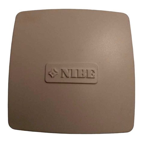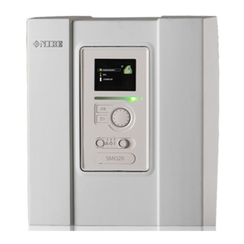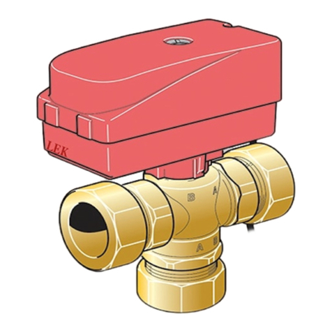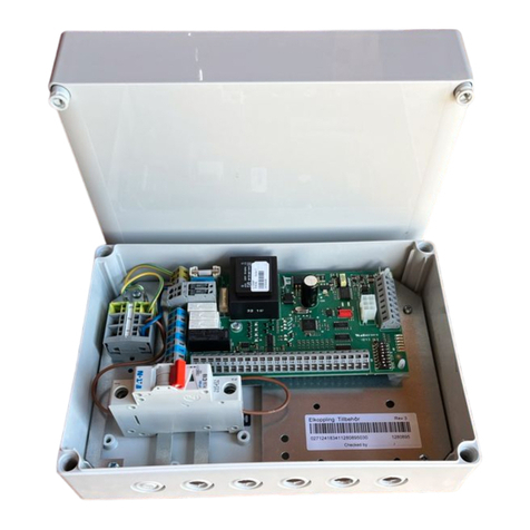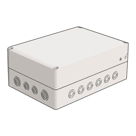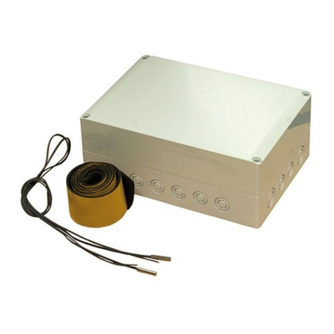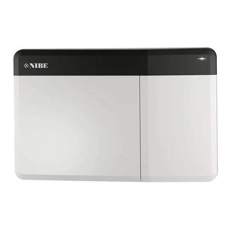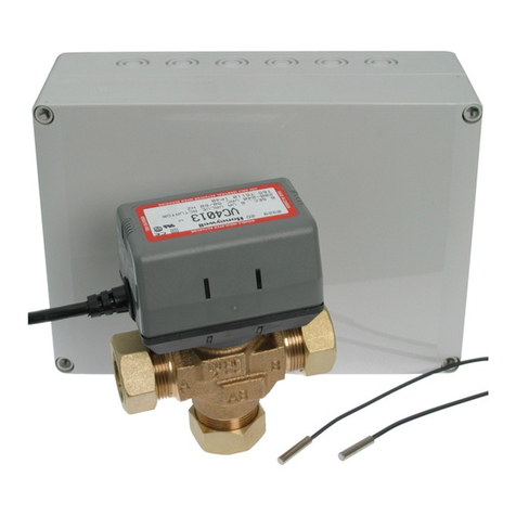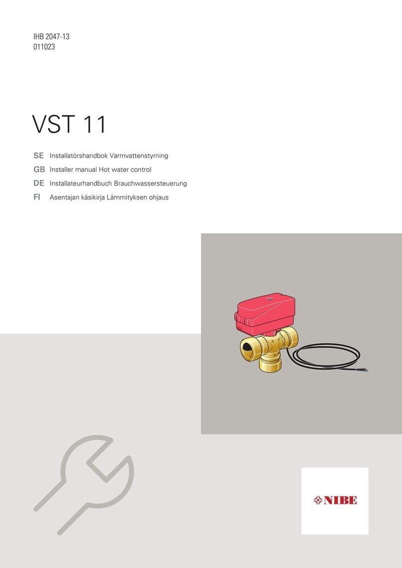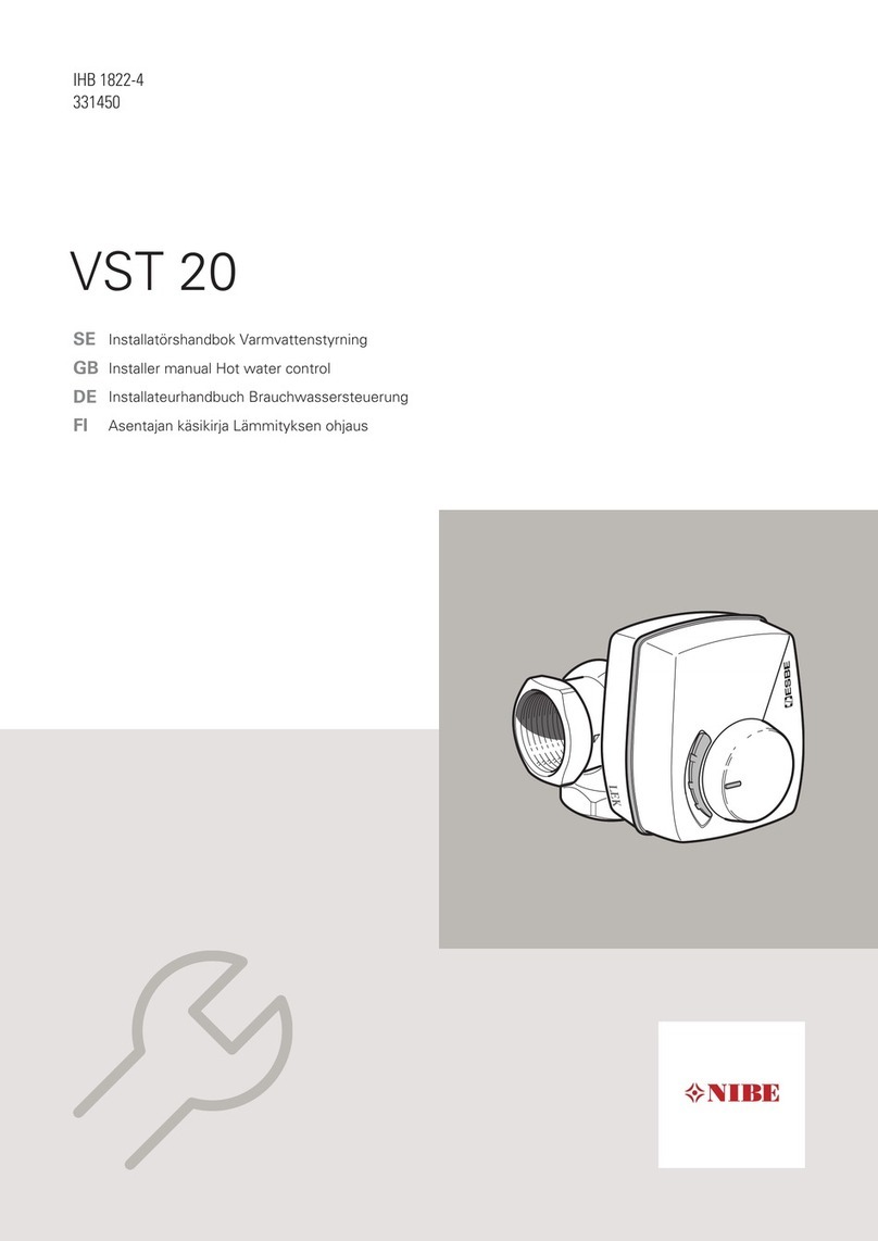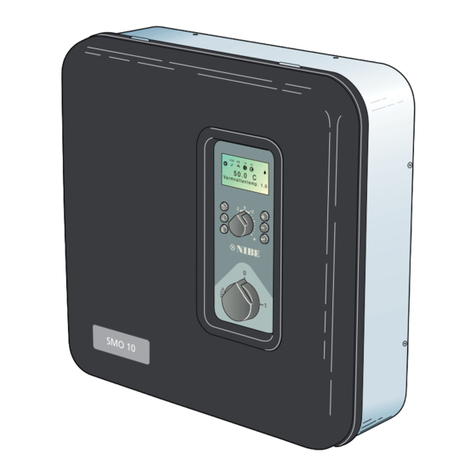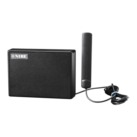
SMO 40 with heat pump, hot water, additional heat and accessory (liquid condensation).
NIBE AB - Energy Systems Box 14, 285 21 Markaryd Tel 0433 - 73 000 Fax 0433 -73 190 www.nibe.se
ODM GB 1417-1
M11566
PAGE 2 (6)
Basic functions
Heat production
SMO 40 is equipped with an outdoor temper-
ature controlled heating control system. This
means that the supply of heat to the house is
regulated in accordance with the chosen setting
of the regulating curve (curve slope and offset).
After adjustment, the correct amount is supplied
to meet the house demand at the present outside
temperature. For heat production, the control
system calculates a heating decit in the form of
"degree-minutes" which means that the engage-
ment of heating production is accelerated the
larger the subnormal temperature in question. To
obtain a system that compensates faster the sup-
plied room sensor should be installed.
Hot water production
During hot water production SMO 40 goes to hot
water mode. No room heat is produced in this
mode. Maximum time for hot water charging can
be adjusted in the menu system. After this, heat-
ing is produced for the remaining period of time
before further water heating can take place.
Hot water charging starts when the hot water
sensor has fallen to the set start temperature. Hot
water charging stops when the hot water tem-
perature on the hot water sensor (BT6) has been
reached.
For occasional higher demand for hot water, the
"temporary lux"・function can be used to raise
the temperature for 3 to 12 hours (selected in the
menu system).
Heat pump
F2025/F2026/F2030/F2040/F2300 can be con-
nected to SMO 40.
The heat pump supplies the house with heating.
When the heating demand exceeds the heat
pump capacity the additional heat is engaged as
additional heating (connected to SMO 40).
Room control
SMO 40 is supplied with a room sensor (BT50).
The room temperature sensor has up to three
functions:
1. Show current room temperature in the con-
trol module display.
2. Option of changing the room temperature
in °C.
3. Makes it possible to change/stabilise the
room temperature.
Install the sensor in a neutral position where the
set temperature is required. A suitable place is on
a free inner wall in a hall approx. 1.5 m above the
oor. It is important that the sensor is not pre-
vented from measuring the correct room temper-
ature by being located, for example, in a recess,
between shelves, behind a curtain, above or close
to a heat source, in a draft from an external door
or in direct sunlight. Closed radiator thermostats
can also cause problems.
The installation operates without the sensor, but
if one wishes to read off the accommodation's
indoor temperature in the SMO 40 display, the
sensor must be installed.
Step controlled additional heat
Heat pump installations that are not dimensioned
to provide the entire heat output requirement re-
quire additional output during cold days. The step
controlled additional heat (if connected) is auto-
matically switched on (in different steps) if the
output is not sufcient to reach the temperature
levels requested by the control computer.
SMO 40 can provide up to 230 V control signals
for the additional heating, i.e. signals to control
external relays, contactors etc, but not to supply
them with power.
Step controlled additional heat can be controlled
by up to three potential free relays in the heat
pump (3 step linear or 7 step binary).
Step in occurs with at least 1 minute interval and
step outs with at least 3 seconds interval.
Shunt controlled additional heat
This connection enables an external additional
heater, e.g. an oil boiler, to assist with heating.
SMO 40 controls a shunt valve and a circulation
pump. If the heat pump does not manage to
maintain the correct supply temperature, the
addition starts. When the boiler temperature
has been increased to about 55°C, the control
module sends a signal to the shunt valve to open
from the addition. The shunt adjusts so the true
flow temperature corresponds with the control
system’s theoretical calculated set point value.
When the heating requirement drops sufficiently
so the additional heat is no longer required the
shunt closes completely. The boiler will be kept
warm for a further 12 hours to be prepared for
any increase in the heating requirement.
External control (AUX-input)
SMO 40 can to some degree control the instal-
lation using signals from external systems (for
example DUC) connected to the three software
controlled inputs (AUX inputs). However, the
alarm and time conditions in SMO 40 override the
external control.
The following functions can be controlled:
nBlocking the compressor in heat pump
nBlocking additional heat
nBlocking heating
nTariff blocking
nActivating temporary lux (extra hot water)
n External adjustment of ow temperature
All control signals should occur with poten-
tial-free relays.
Software controlled output (AUX
output)
It is possible to have an external connection
through the relay function via a potential free
variable relay (max 2 A) on the terminal block
AA2-X4.
Optional functions for external connection:
nIndication of buzzer alarm signal (preselected
at the factory).
nControl of external circulation pump.
nControl of circulation pump for hot water cir-
culation.
If any of the above is installed to terminal block
AA2:X4 it must be selected in the control system.
Function


