Creality 3D CR-10mini Series User manual

CR-10mini Series 3D Printer User
Manual
User Manual is for the CR-10 Series of 3D printers. It is also
applicable for the CR-10S/CR-10 S4/CR-10 S5.
But CR-10 mini without T-Bracket (Right) & Decoration Strip.
Due to the different types of devices ,Hardware and software upgrade. the
devices have little different, it is normal phenomenon. Subject to actual
device received.
Detailed instructions for using are available in the TF card.
V.6.0

Parameters
Basic Parameters
Model
CR-10
CR-10S
CR-10 S4
CR-10 S5
CR-10mini
Printing Size
300*300*400mm
300*300*400mm
400*400*400mm
500*500*500mm
300*220*300mm
Molding Tech.
FDM
Nozzle Number
1
Slice Thickness
0.1mm-0.4mm
Nozzle Diameter
Standard 0.4mm
Precision
±0.1mm
Fliament
1.75mm PLA
File Format
STL/OBJ/AMF
Working Mode
Online or TF card offline
Slice Software
Creality Slicer/Cura/Repetier-Host/Simplify3D
Power Supply
Input:AC 115V/230V 50/60Hz
Output:DC 12V
Total Power
270W
270W
250W
270W
270W
Bed Temp.
≤100℃
≤100℃
≤60℃
≤60℃
≤100℃
Nozzle Temp.
≤250℃
Resume Print
NO
Yes
Yes
Yes
Yes
Filament Detector
NO
Yes
Yes
Yes
NO
Daul Z-Axis
NO
Yes
Yes
Yes
NO
language Selection
NO
EN/CN
Operating System
Windows XP/Vista//7/8/10 MAC/Linux
Printing Speed
≤180mm/s,Normal 30-60mm/s

CONTENTS
Dear consumers,
Thank you for choosing our products. For the best experience, please read the
instructions before operating the Printer. Our 3D team will always be ready to give
you the best service. Please contact us via the phone number or e-mail address
provided at the end when you encounter any problem with the Printer.
For a better experience in using our product, you may learn how to use the Printer in
the following ways:
View the accompanied instructions and videos in the TF card.
Visit our official website www.creality3d.cn You will find relevant software/hardware
information, contact details and operation and maintenance instructions on the
website.
Introduction................................1
General List................................2
Device Installion.........................3
Cable Connection......................4
Screen Information....................5
Loading Filament...…............…6
Platform Adjustment.................7
Software Installation.................8
For the First Printing................9

NOTES
1. Do not use the printer any way other than described herein in order to avoid
personal injury or property damage.
2. Do not place the printer near any heat source or flammable or explosive objects.
We suggest placing it in a well-ventilated, low-dust environment.
3. Do not expose the printer to violent vibration or any unstable environment, as
this may cause poor print quality.
4. Before using experimental or exotic filaments, we suggest using standard
filaments such as ABS or PLA to calibrate and test the machine.
5. Do not use any other power cable except the one supplied. Always use a
grounded three-prong power outlet.
6. Do not touch the nozzle or printing surface during operation as they may be hot.
Keep hands away from machine while in use to avoid burns or personal injury.
7. Do not wear gloves or loose clothing when operating the printer. Such cloths
may become tangled in the printers moving parts leading to burns, possible
bodily injury, or printer damage.
8. When cleaning debris from the printer hotend, always use the provided tools.
Do not touch the nozzle directly when heated. This can cause personal injury.
9. Clean the printer frequently. Always turn the power off when cleaning, and wipe
with a dry cloth to remove dust, adhered printing plastics or any other material
off the frame, guide rails, or wheels . Use glass cleaner or isopropyl alcohol to
clean the print surface before every print for consistent results.
10. Children under 10 years of age should not use the printer without supervision.

Filament Holder
Control Box
Nozzle Assembly Connection
Platform Connection
Power Cable Connection
Extruder (E) Stepper
X Limit Switch
X Stepper
Z Limit Switch
Z Stepper
Y Limit Switch
Y Stepper
Nozzle Kit
TF Slot and USB Port
Display Screen
Control Knob
Voltage Selection
Platform
Base Frame
Z Gantry Frame
A、 Introduction
1

uTool list
Tool Box Control Box
No.
Image
Name
Qty
No.
Image
Name
Qty
No.
Image
Name
Qty
1
Spool & Nuts
1set
7
Power Cable
1
13
Spade
1
2
Spool Holder
1
8
USB Cable
1
14
Cable Ties
1set
3
TF Card & Card
Reader
1set
9
PTFE Tubing
(spare part)
1
15
Hex keys, Wrench
& Screwdriver
1set
4
T-Bracket (Right)
1
10
Nozzle Cleaner
1
16
Spare Parts
1set
5
T-Bracket
& Z Limit Switch
(Left)
1
11
Filament(200g)
1
17
Decorative Strip
1
6
M5X25 Bolt & Lock
Washer
4 sets
12
Diagonal Pliers
1
18
Thumb Screw
3
Base Frame Gantry Frame
*CR-10 mini without T-Bracket (Right) & Decoration Strip.
B、General List
2

Note: Make sure that the nut for
profile ha s be en tur ned by 90°
before fastening the
T-shaped fixing block.
M5X25
4pcs *CR-10 mini without T-Bracket (right).
uInstall the Gantry Frame
uInstall the T-shaped fixing block.
C、Device Installtion
3

Install decoration belt into the
notch, starting from one end. Cut off the excess material with
the diagonal pliers
Attach the Decorative Trim to all
parts needing to be decorated.
Attach the Bracket
with two thumb screws.
Attach Spool Holder
with included Nuts
Finished
◆ Install the Rack
◆ Install decoration strip
*CR-10mini without Decoration Strip.
*The decoration Strip is available in various colors. The pictures above are for reference only.
4

Y Stepper and Limit Switch
Extruder (E) Stepper
X Stepper and Limit Switch
Z Stepper and Limit Switch
Connect the aviation connectors to the
ports with corresponding pins
Connect the Stepper Motors according to
the yellow labels on the 6pin (4-wire) side.
Connect the Limit Switches according to the
yellow labels on the 3pin (2-wire) side.
•Select the correct input voltage to match your local
mains (230V or 115V)
•Damage can occur if voltage is set incorrectly.
•Make sure the power cable is connected.
D、Introduction
5

Set Temperature of
the Nozzle
Current Temperature
of the Nozzle
Set Temperature of
the Hot Bed
Current Temperature
of the Hot Bed
Part Cooling Fan
Speed
Current Location of
the nozzle
Print Time
Print Progress
Prompt Message
Print Speed
Device Model
Push:OK/Enter Sub Menu
Turn:Change Option/Value
E、 Screen Information
6

1、Preheat
Method 1
Method 2
2、Feed Filament
Press and hold the extruder lever then insert the1.75mm filament through
the small hole of the extruder. Continue feeding until you see filament come out
the nozzle.
Tip:How to Replace the Filament?
1、Cutting filament near the Extruder and slowly feed new filament until they
are fed into the new filament.
2、Preheating the nozzle and withdraw the filament quickly and feed the new
filament.
7
F、Loading Filament
7

1. Prepare →Auto Home. Waiting for the nozzle to move to the left/front of the platform.→ Prepare→Disable Steppers(Close stepper drive,release
motor)
2. Move the nozzle the front/left leveling screw and adjust the
platform height by turning the knob underneath. Use a piece of
A4 paper (standard printer paper) to assist with the adjustment,
making sure that the nozzle lightly scratches the paper.
3. Complete the adjustment of the screw on all 4 corners.
4. Repeat above steps 1-2 times if necessary.
12
34
1111111
11111
The nozzle is too far away from the
platform, so the consumables can not
adhere to the platform.
Filament are extruded evenly, just
sticking on the platform.
The nozzle is too close to the platform,
and the filament are not extruded
enough, even scraping the platform.
G、Bed Leveling
8

1. Double click to
install the software.
3. Select language→Next→Select your machine→Next→Finish.
2、Double click to
open the software.
H、Software Installation
9

1.Slicing
2.Printing
Insert the TF card→ Print → Select the file to be printed.
Open the software→Load→Select the file→Wait for slicing to finish ,and save the gcode file to TF card.
I、First Printing
10

After- Sales Service
Service
1, The printer can be returned within seven days, 15 days replacement,
one year warranty, lifetime maintenance.
Replacement requirement
1. The appearance of the product is intact, without damage, scratches,
smudges, cracks, deformation, etc.;
2. Machine parts, tools and others are complete;
3. Provide a complete and valid purchase invoice and warranty, product
number should be the same.
Warranty coverage
1. The following accessories are not included in the warranty coverage
if they are not damaged by transportation: platform sticker; platform
forming plate; acrylic cover; card reader and TF card; platform glass;
USB cable; filament; rack and tools,etc.
2. Profile: Before we deliver the goods, we will do the machine test, so
maybe there will be light scratch, or due to long-distance
transportation, which scratch the profile a little bit. in the premise of
not affecting the normal use, in principle, not within the scope of
warranty;
3. Nozzle assembly (nozzle, heating block, throat pipe,heat sink, Teflon
tube, etc.) warranty period is 3 months, if it is damage after the
warranty expires, you need to purchase another one;
4. Motherboard, LCD display, power supply, hot bed,warranty period is
12 months, if there are quality problems, you can get free
maintenance; over the warranty period, can be sent back to the
original factory maintenance, the users need to bear the return
shipping and maintenance costs;
5. Not included in warranty coverage:
(1) It is not possible to provide an effective after-sales service card or
serial number;
(2) The whole machine and components exceed the warranty period;
(3) Equipment failure or damage caused by unauthorized modification
of the equipment (private modification includes: 1. modification of
the nozzle assembly; 2. modification of the machine structure; 3. use
of third-party components; 4. use of third-party firmware procedures
or change the original Factory firmware program, etc.);
(4) Equipment failure or damage due to incorrect installation and use;
(5) Equipment failure or damage caused by the use of the equipment
in a working environment not specified by the product;
(6) Equipment failure or damage due improper use (beyond workload,
etc.) or maintenance (moisture, etc.);
(7) Equipment failure or damage due to the use of other branded
components or low quality consumables.
Statement:
For better highlighting the function and effectiveness of 3d printer and
promoting the development of global market economic, strengthening
the user self-discipline of 3d industry and establishing a good image
of 3d printing, since Creality 3d printer have passed all kinds of
authorized product certificates and quality management system.hereby
we declare that it is strictly forbidden to use our printer to print any
products or equipment that are in violation of the specific country and
regions legislation.

SHENZHEN CREALITY 3D TECHNOLOGY CO.,LTD.
11F&Room1201,Block3,JinChengYuan,TongshengCommunity,Dal
ang,LonghuaDistrict,Shenzhen,China,518109
Official Website: www.creality3d.cn
Tel: +86 755-2105 9455
E-mail: info@creality3d.cn cs@creality3d.cn
The revision date: April 24,2019
This manual suits for next models
5
Table of contents
Other Creality 3D 3D Printer manuals
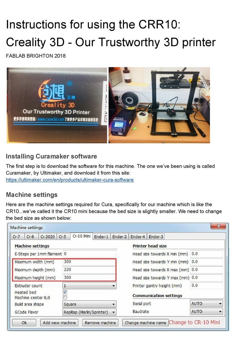
Creality 3D
Creality 3D CRR10 Installation and operation manual
Creality 3D
Creality 3D CR20 Series Manual
Creality 3D
Creality 3D LD-001 Series Manual
Creality 3D
Creality 3D Ender-3 Pro Assembly instructions
Creality 3D
Creality 3D HALOT-ONE User manual
Creality 3D
Creality 3D Ender-3 Pro Assembly instructions
Creality 3D
Creality 3D Ender-3 Pro Assembly instructions
Creality 3D
Creality 3D CR-2020 Operating and maintenance instructions
Creality 3D
Creality 3D Ender-3 Pro Manual
Creality 3D
Creality 3D Ender-5 Plus User manual

