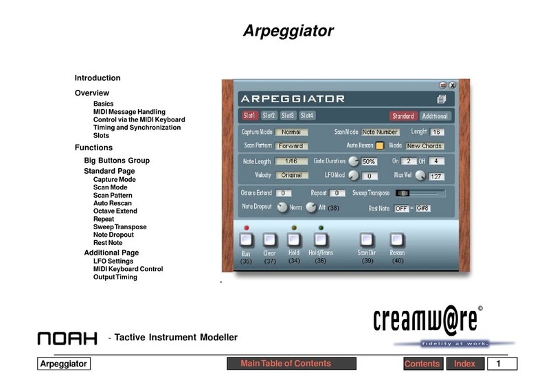
CreamWare Noah Minimax User manual

Index 2Minimax Contents
Introduction
What’s the Max about the
Mini?
Just what is it about the Minimax?
Todayyouwouldprobablynotexpecttoo
much in terms of sound from a
synthesizer with 3 oscillators and noise,
a mixer, followed by a filter with an
amplifier and two envelope generators.
But we’re not talking about just any
synthesizer, we’re talking about
the
synthesizer!
Minimax is an emulation of the probably
best-knownofallvintage synths.It’s sim-
ple structure makes it easier to learn
soundcreation techniquesthanon many
other synthesizer models. And its sound
is famous.The oscillators are strong and
powerful, the filter pack and envelope
generatorsblindinglyfast.
Many have tried to duplicate these
characteristics. However, attempts by
both hardware and software
manufacturershavefailed.Withhardware,
thedifferentelectroniccomponentsoften
usedchangedthesound.Andinsoftware
only some parts of the original, such as
the filter, were successfully emulated.
Other elements, like the oscillators and
envelopes, were imported from outside
sources.
CreamWare knows how difficult a true
emulation is. From today’s perspective,
the Miniscope and Miniscope MkII must
be considered as great synthesizers in
their own right, but not as emulations of
theoriginal.
Minimax is different than anything that’s
come before. Minimax does not just
emulate parts of the instrument - Mini-
max
is
the instrument.Where there have
been limits to the hardware, such as ori-
ginal components no longer being
available, and where software has not
daredto go,theregoes Minimax.
With the Minimax we modeled all
important sound elements on the origi-
nalcircuitdiagrams.Andthroughoutthe
process we constantly recalibrated our
design to conform with the original so
that even the positions of the controls
agree. Still the reproduction was not
exact. Calibration and adjustment was
only part of the work we had to do.
Wehadyetanotherhurdletojumpbefore
we could claim success. The original
synthproducesfrequenciesthat,hadwe
relied on the usual algorithms, would
have led to aliasing. And those familiar
with aliasing know what an unpleasant
noise it is to have in a signal. The
modules used in the Minimax are built
onnewly-developedalgorithmsfreefrom
aliasing.Forthisreason Minimaxeasily
handles even the wildest filter, FM, or
oscillator modulations. And the beauty
ofit is - Minimaxalwayssoundslikethe
original. Minimax represents the
pinnacle of synthesis algorithm
development.

Index 3Minimax Contents
Structure and Overview
Liketheoriginal,Minimaxhasanoscillator
section with three oscillators. Oscillator 3
can also serve as an LFO.The oscillator
signalsaremixedwithnoiseoranexternal
signal,ifdesired,inthemixersection.From
the mixer, the combined signal is sent to
anamplifier andafilter, eachof whichhas
an associated envelope generator with
adjustableattack, release andsustain.
The quality of the algorithms is readily
apparentin allsections ofthe synthesizer.
Thefull-range oscillators producesignals
with extended highs giving you soaring
sound with great vitality and energy. We
alsopaidcarefulattention tothesaturation
behavior of the mixer section, both for
internal and external signals. Saturation
givesthe sound more abilitytopenetrate.
Morepower.
Although the goal of the development of
Minimax was to create an absolutely
faithful reproduction, we couldn’t resist
addingafewenhancements.Theenvelopes
have adjustable velocity and switchable
trigger behavior, and the normal low-note
priority can be switched instead to last-
notepriority.
Our love of detail is also apparent in the
graphic front panel. The controls were
treated with particular care so that they
correspond exactly to the originals.If you
still have any of your old sound sheets,
you can set them up on the Minimax and
then store them as presets!
The filter, in particular, benefits from the
new algorithms. Although previous filters
hadresonance,itwasneverasconvincing
astrueanalogresonance.Withdigitalfilters
designers had to make sure that aliasing
would not develop during filter sweeps.
Therefore,manyfilterslimit theresonance
range (or do not allow it to fully open) to
prevent the signal from exceeding the
aliasingthreshold (the Nyquistfrequency,
half the sample rate). Filter sweeps with
these filters are useful, but are less lively
than they could be. The Minimax filter is
completely convincing all down the line.
The filter has a unique liveliness and
producesall the resonanceanddistortion
you could ever wish for in a filter.
Resonance can be fully opened up and
sweepsarefreeof aliasing - evenbeyond
halfthe sampling frequency.
Finally, the envelope generators need not
shrink from comparison with their analog
counterparts either.Notonlyaretheyfast
- they reproduce the overall behavior of
the original with great accuracy.

Index 4Minimax Contents
Operation
The Minimax graphic panel is switchable
to display either the main or an auxiliary
panel.The layoutof the sections provides
a rough indication of the synthesizer
structure. The oscillators, mixer section,
and the filter with envelope and amplifier
with envelope section are all on the main
panel.The effects and global parameters
areon the
Add
panel (Addstandsfor"ad-
ditional”—thatis,extended parameters).
To switch from one view to the other use
theswitchesinthe upperleftcorner of the
panel.
A text field for the current preset, and an
icontoopenthe Preset List are located in
the upper right corner, along with the On
Topand Closebuttons.
To maintain the graphic panel in the
foreground, click the On Top button. Use
the Close button to close the panel (and
also the Preset List dialog if it is open).
Preset list
OnTop
Close
Current Preset

Index 5Minimax Contents
Controllers
This section covers the general settings
and provides some tips regarding
modulation techniques. The Add page
section contains descriptions of some
otherparameters.
Tune
This control adjusts the overall tuning of
the instrument. The range is +/- 2.5
semitones.
Glide On
Enables the Glide function.When glide is
ononenoteglidesintothenext(glissando)
atanadjustable speed(seeGlide,below).
Glide
When the glide function is enabled this
controladjusts the rate oftherise or fallin
pitchbetween notes.
ModulationMix
Controlsthe proportion ofoscillator3 and
noise in the modulation signal. The
resulting signal is used to modulate the
oscillatorbank andfilter.To hearthe result
youmusthavemodulationswitchedonand
themodulationwheelset toproducesome
intensity.
DecayOn
Switchesthedecaytimesoftheenvelopes
to assume the release time.The release
times are then controlled with the decay
controls. If Decay is off, the minimum
release time is used.

Index 6Minimax Contents
BendRange
Sets the maximum pitchbend deflection.
The range is from 0 to 24 semitones.
ModulationWheel
Inprinciple,theintensityof themodulation
signal applied to the oscillators and filter
is controlled by the modulation wheel. In
theoriginalthiswastheonly waytocontrol
modulation. For greater control we’ve
added modulation intensity and offset
controls as well.
ModulationIntensity
Sets the maximum intensity of the of the
modulation applied to the oscillator bank
andthe filter by the modulation wheel.
ModulationOffset
The fundamental intensity of the
modulationsignal applied totheoscillator
bank and the filter with the modulation
wheel at zero. The modulation wheel
increases the intensity according to the
offset and intensity settings.
Low Note On
Enabling Low Note On gives low notes a
priority over high notes. A higher note
cannotdisplacealownote.Whenswitched
off, the last-played note will always have
priority.
Retrig On
Switches the retrigger mode of the
envelopegenerators fromlegatoto retrig.
When Retrig is on, the envelopes trigger
every time a new key is pressed, even if
youareplayingalegatostyle(thatis,when
you play a new note before you release
the previous one). In legato mode the
envelopestrigger onlyifthe previousnote
hasbeen released.
With Low Note on and Retrig off, the
behaviorof theMinimax isthe sameas that
of the original. For some presets, such as
pads and sequencer sounds, it may be
appropriate to switch Low Note off and
Retrig on.
SingleOn
Forces the instrument to operate in sin-
gle-voice mode, regardless of how many
voices are actually currently loaded.
Guarantees proper performance of solo
soundswith portamento.

Index 7Minimax Contents
CV
Theoriginal synthhad three CVinputsfor
external control of the sounds.One input
controlled oscillator pitch, one controlled
filter cutoff and one controlled volume. In
the Minimax, these three parameters can
be modulated via aftertouch, with
modulation intensity adjustable per mod
destination.
OSC
Intensity and direction of oscillator pitch
modulation. Permits generation of an
oscillator pitch bend under aftertouch
control.
Filter
Intensity and direction of filter cutoff
modulation. Permits generation of filter
sweepsunder aftertouchcontrol.
Loudness
Intensity and direction of volume
modulation. This option is particularly
interesting in connection with the internal
feedbackfeature.Theamountofoverdrive
can be controlled via aftertouch.
External Input
Source
Selecttheexternalsignalsourcehere(see
chapter‘Mixer’).

Index 8Minimax Contents
Oscillator Bank
The oscillator bank consists of three
oscillators.Each oscillator hascontrolsto
adjusttheoctaveandselectthewaveform.
Oscillators 2 and 3 also have Frequency
controlsfordetuning.Oscillator3can also
serve as a modulation source in which
case it ignores frequency input from the
keyboard and functions as an LFO. The
LFO rate is then controlled by the Range
andFrequency controls.Pitch modulation
can be turned on or off with a switch.
Range
Sets the octave of the oscillators. The
octaves available are Lo, 32’, 16’, 8’, 4’
and 2’. The values 32’ and 16’ are low
octaves suitable for bass while 8’ and 4’
are good for lead voices.To use oscillator
3 as an LFO, select the value Lo.
Waveform
Selectsthewaveformforanoscillator.Each
oscillator can produce one of six possible
waveforms: triangle, a mix of triangle and
sawtooth,sawtoothup,square,widepulse,
and narrow pulse. In keeping with the
character of an LFO, oscillator 3
substitutesa sawtoothdownwaveform for
thetriangle/sawtooth mix.
Frequency
Adjuststhetuningofoscillators2and3with
respecttooscillator1.Thescalingindicates
the amount of detune in intervals.The
maximumadjustmentisabout9semitones.
OSC3Control
This switch sets oscillator 3 to ignore
keyboard frequency control.Youcan then
useoscillator3toprovideafixedfrequency
asasonicelement,ortoserveasanLFO.
Whenusing oscillator 3asan LFO, adjust
the coarse frequency with the Range
control and the fine tuning with the
Frequencycontrol.
OscillatorModulation
Enables pitch modulation for the three
oscillators. Select the modulation source
signal - which can be noise, oscillator 3,
oracombinationofboth-underModulation
Mix. The intensity is controlled by the
modulation wheel and associated
parameters.

Index 9Minimax Contents
Mixer
The Mixer combines the various signals
beforesendingthem tothe filter.Uptofive
signals can be included in the mix:
oscillators1-3, plus noiseandan external
signal.For each signalthereis a switchto
include or exclude it from the mix, and a
level control. External signals can be
amplifiedtoproducedistortionthatyoucan
use for special sonic effects.
Volume
Adjusts the level of the respective signal
in the mix.
FeedbackOn
Withfeedbackon,thesynthesizer’soutput
is internally routed to the external input.
YoucanthenusetheExternalInputVolume
controltoadddistortiontotheoverallsignal
as a sound element. A signal connected
totheExternalinputisignoredinthismode.
NoiseVolume
Controlsthelevelofthenoisesignal.When
noiseis used as amodulationsource,the
volumelevel has noeffectonthe intensity
ofthe modulation.
NoiseWhite/Pink
Selects the noise ‘color’. When noise is
usedasamodulationsource,thecolorhas
aneffecton themodulation.
External InputVolume
Thevolumeleveloftheexternalsignal.For
thistohaveaneffect,asoundsource must
beconnected to theAudioinput of the Mi-
nimax. A signal lamp above the control
servesasalevelmeter.Thebrightnessof
thelampindicatesthestrengthofthesignal
outputor an over condition.

Index 10Minimax Contents
Modifiers
Inthissection anamplifierand filterfurther
processthe signal.Thefilter andamplifier
eachhas its ownenvelopegenerator with
Attack,Sustain,andReleasecontrols.The
Releasetimecan besettotheDecaytime
byaswitchintheControllerssection.
Filter
Alongwith theenvelope, thefiltercontrols
changes in the tone color. The filter is a
24dB/octave low-pass filter. Frequencies
beneaththeCutofffrequencypassfreely,
whilefrequenciesaboveareattenuatedby
24dB/octave.There’sprobablynotalot to
sayaboutthisfilterotherthanitisgenerally
consideredtobeoneofthebestsounding
filters ever put in a synthesizer.The Mini-
max confirms this.
CutoffFrequency
The cutoff frequency is the frequency
above which the spectrum is cut—
overtonesareattenuated.Thiscontrollets
you adjust the cutoff frequency manually.
Emphasis
Thisis theresonancecontrol. Resonance
resultsfromthecouplingofthefilteroutput
to the filter input, thereby reinforcing the
frequencieslyingnearthecutofffrequency.
At the maximum setting the filter begins
to oscillate, producing a pure sine tone at
thecutofffrequency.Youcanuseemphasis
as a possible sixth sound source.
Amount of Contour
Adjusts the intensity of the envelope
modulation.The cutoff frequency follows
theprogression (contour) oftheenvelope
with the degree of change controlled by
thissetting.Atthebeginningandendpoints
of the envelope the cutoff is the adjusted
CutoffFrequency.

Index 11Minimax Contents
Attack
Durationof the first envelopesegment.In
the attack phase the cutoff frequency
increasestoitsmaximum valueinthetime
adjusted here. Adjust the amount of the
increase with the Amount of Contour
control.Themaximumvalueisdetermined
by the adjusted cutoff frequency and the
Amountof Contoursetting.
Decay
Thedurationofthe decaysegment.Inthe
decay segment, the cutoff frequency falls
to the sustain level.If the Decay switch in
the Controllers section is set to "on", the
time setting here is applied to envelope
release.
Sustain
The envelope’s third segment.This is the
level held after the decay segment
completes.The actual cutoff frequency is
determined by this value and the Amount
ofContour setting.
Release
The fourth envelope segment. This is
enabled only when Decay is switched on.
Thereisnodirectcontroller for therelease
phase.In the releasephasethe envelope
falls toits minimumvalue.Thisisthe value
set by the Cutoff parameter. The rate at
which it falls is determined by this setting.
Velocity
Theamountofmodulationoftheenvelope
as influenced by key velocity.This setting
controlsthe envelopepeaklevel between
minimumandmaximumdependingonhow
hardyoustrikethekeysonyourkeyboard.
Thiscontrols howmuchyourplayingstyle
(aggressiveor gentle)influencesthe tone
quality.
Filter Modulation
Enables additional filter modulation.The
Modulation Mix section serves as the
modulation source.The signal can come
fromOscillator 3, Noise,ora combination
ofboth.TheModulationWheelcontrolsthe
intensityof the modulation.
KeyboardControl
CutoffKeyfollowisenabledintwostages.
With the first switch, the cutoff frequency
followsthekeyboardpositionat1/3octave
per keyboard octave. With the second
switch the cutoff frequency follows the
keyboardpositionat2/3octaveperoctave.
With both switches turned on, the cutoff
frequency rises by an octave for each
keyboardoctave.

Index 12Minimax Contents
Loudness Contour
Along with the envelope generator, the
amplifier controls the progression of the
volume level of the sound.
Attack
The first envelope segment. During the
attack phase of the envelope the volume
reaches its maximum level. This setting
adjusts how quickly the level is reached.
Decay
Thesecondenvelopesegment.Duringthe
decay phase of the envelope the volume
falls tothelevelsetbytheSustaincontrol.
If the Decay switch in the Controllers
sectionis setto"on", thetime settinghere
isappliedtothe envelope’sreleasephase.
Sustain
The third envelope segment. This is the
volume levelat which the sound is held at
theend of thedecay segment.
Release
The fourth envelope segment. This is
enabled only when Decay is switched on.
Thereisnodirectcontroller for therelease
phase.In the releasephasethe envelope
falls to its minimum value, silencing the
sound. The rate at which it falls is
determined bythe Decay setting.
Output
Velocity
Theamountofmodulationoftheenvelope
as influenced by key velocity.This setting
controlsthe envelopepeak level between
minimumandmaximumdependingonhow
hardyoustrikethekeysonyourkeyboard.
Thiscontrols howmuchyourplaying style
(aggressive or gentle) influences the
volume level of the sound.
Volume
Overall volume level of the synthesizer.
This control is located before the effects
section, so it can also be used to control
the effects in order to, for example, avoid
distortion in the Flanger at high feedback
levels.

Index 13Minimax Contents
Index
A
Amount of Contour 10
Attack 11, 12
B
Bend Range 6
C
Close 4
Contour 10
Controllers 5
Cutoff Frequency 10
CV 7
D
Decay 11, 12
Decay On 5
E
Emphasis 10
External Input 7
External Input Volume 9
F
Feedback On 9
Filter 7, 10
Filter Modulation 11
Frequency 8
G
Glide 5
Glide On 5
I
Introduction 2
K
Keyboard Control 11
L
Loudness 7
Loudness Contour 12
Low Note On 6
M
Miniscope 2
Miniscope MkII 2
Mixer 9
Modifiers 10
Modulation 8
Modulation Intensity 6
Modulation Mix 5
Modulation Offset 6
Modulation Wheel 6
N
Noise Volume 9
Noise White/Pink 9
O
OnTop 4
Operation 4
OSC 7
OSC3 Control 8
Oscillator 8
Oscillator Modulation 8
Output 12
Overview 3
P
Pink 9
Presets 4
R
Range 8
Release 11, 12
Retrig On 6
S
Source 7
Structure 3
Sustain 11, 12
T
Tune 5
V
Velocity 11, 12
Volume 9, 12
W
Waveform 8
White/Pink 9
Other CreamWare Synthesizer manuals
CreamWare
CreamWare PRO-12 ASB User manual
CreamWare
CreamWare Noah Installation instructions
CreamWare
CreamWare Pro-12 User manual
CreamWare
CreamWare Noah Interpole User manual
CreamWare
CreamWare Noah Vectron Player User manual
CreamWare
CreamWare MINIMAX ASB User manual

CreamWare
CreamWare Noah Vocodizer User manual
CreamWare
CreamWare Noah Step Sequencer User manual
CreamWare
CreamWare MINIMAX Klangbox User manual

CreamWare
CreamWare PRO-12 ASB User manual

