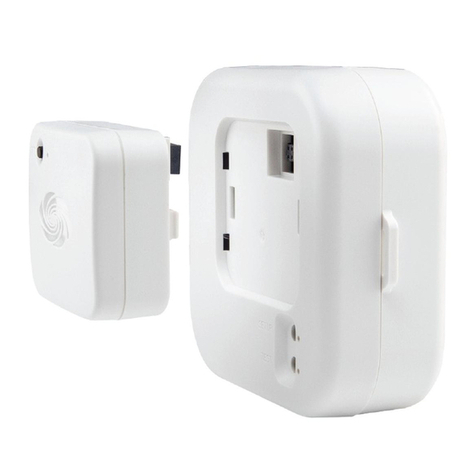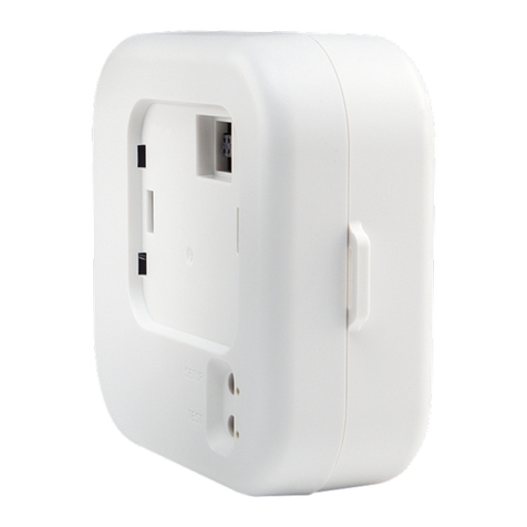
CRESTRON STIRP Infrared Emitter
CONNECTING THE STIRP
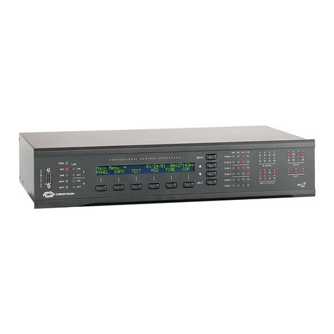
Insert the mono mini plug of the STIRP into one of the four IR OUT ports of
the ST-CP, shown below. The STIRP can also connect to other Crestron
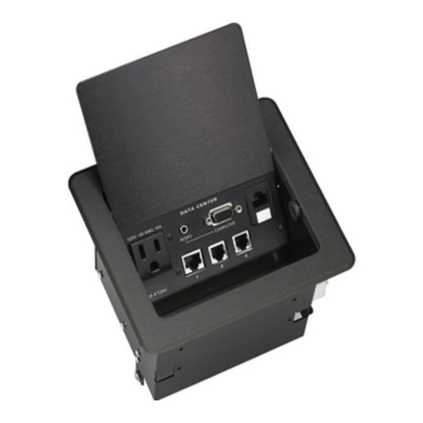
devices such as the IR Splitter (ST-SPL) or SmartPresenter (SP-1).
RF
ABCD
IR OUT
COMA
PCNET
12 VDC
.5A
COMB
VCR
IR Sensor
Window
ATTACHING THE STIRP TO OTHER LOCATIONS
Rather than affixing the low output side of the STIRP shell directly over the
IR sensor window, the shell can be positioned as much as three feet away
on the axis of the IR sensor window. The high output side of the STIRP shell
permits control at this greater distance. Placement of the STIRP on surfaces
just above or below the IR sensor window, as shown below, may provide a
more pleasing aesthetic appearance. However, be sure to position the STIRP
shell so that the edge of the component does not block the IR signal. Also
placing the STIRP shell on a cabinet door may result in interruption of the IR
signal if the door is opened.
Crestron STIRP
Infrared Emitter
Installation Instructions
Possible locations of STIRP shell attached to shelf directly below
or above IR sensor window
Shelves
Crestron Electronics, Inc.
15 Volvo Drive Rockleigh, NJ 07647
Tel: 888.CRESTRON / 201.767.3400
Fax: 201.767.7576 / BBS: 201.767.5506
www.crestron.com
Specifications subject to
change without notice.
Doc. 5674A
06.99
