Croplands MHL12 User manual

GP-OMMHL-A
WWW.CROPLANDS.COM.AU
CROPLANDS
S P R AY B O O M S
OPERATORS MANUAL
STOP
BEFORE COMMENCING
operation, ENSURE you read
& understand this manual, its
contents, and any additional
information supplied.
HYDRALINK MHL 12 | HYDRALINK MHL15

GP-OMMHL-A
2
INTRODUCTION
GENERAL MANAGER’S WELCOME
Congratulations on the purchase of your new Croplands sprayer.
Croplands has been in the business of building and selling spraying
equipment since 1972. For over 49 years we have been supplying spray
equipment to farmers, contractors, growers and all our customers involved
in growing crops and in the control of pests and diseases.
Croplands is a wholly owned subsidiary of Nufarm Ltd, the largest supplier
of crop protection chemicals in Australasia, and one of the fastest growing
global suppliers world-wide.
At Croplands, we pride ourselves on our commitment to supplying machinery
that is at the forefront of the industry’s needs. We believe we can back up
our products and through constant research and development, bring to you
the best equipment you can find.
We welcome any feedback from you about our equipment.
On the back page, you will find our contact details, and locations where
our staff can be reached during business hours.
After hours, you can email us and expect a reply the following morning.
Please read this manual in its entirety before you operate your sprayer.
This will ensure you have a trouble-free start up.
We trust you will get years of good use from your Croplands Sprayer.
Yours Sincerely
Sean Mulvaney
General Manager
Croplands has taken steps to ensure this operator’s manual is as current and as accurate as possible.
Due to the ever-changing markets of cropping and farming, Croplands is constantly striving to be at the
forefront of innovation and technology. While the information in this manual is considered accurate at the
time of writing, Croplands reserves the right to change this information without notice. Croplands will not
accept liability for any inaccuracy in this publication, or changes forthwith.
Sean Mulvaney
General Manager

3
CONTENTS
SECTION 1
IMPORTANT INFORMATION
About this manual 4
Before operating your sprayer 4
Terminology 4
Warranty Policy 5
SECTION 2
SAFETY 6
SECTION 3
PRODUCT IDENTIFICATION
& SPECIFICATION
Booms Hydraulic 7
BARGAM BOOM MANUAL 134
SECTION 4
ASSEMBLY DRAWINGS
PARTS & SCHEMATICS
MHL12 parts identification 41
MHL15 parts identification 45

GP-OMMHL-A
4
SECTION 1
IMPORTANT INFORMATION
ABOUT THIS MANUAL
This manual provides assembly, setting up, operating and
maintenance instructions for the MHL spray booms.
Some model types also have different options available.
Some features explained in this manual may not be
applicable to your boom.
Please pass on this manual with the sprayer or boom at
the time of resale for use by the new owner.
This manual, GP-OMMHL-A, was first published in
November 2021.
Check online as there may be more recent revisions of
this manual. www.croplands.com.au
TERMINOLOGY
These terms/symbols used throughout this manual:
NOTE
This Note sign is in place to convey useful
information and will help you to identify
the best possible way to operate the
machine.
CAUTION
This Caution sign shows the potential for
incident. An incident may include damage
to the machine itself, or possible injury to
the operator.
WARNING
This warning sign shows the potential for
risk or injury and highlights the need for
steps to be taken to protect ones safety.
DANGER
This Danger sign will be used in areas where
the highest risk is present. Always read the
information on these signs and ensure you
are taking steps to prevent risk or injury.
BEFORE OPERATING YOUR SPRAYER
Before attempting to use your sprayer, make sure you
read all Operator Manuals for this sprayer including but
not limited to:
This Operator's Manual, and all other supplied
manuals for items such as Pumps, PTO etc.
And properly understand:
• All Safety Issues
• Assembly & installation instructions
• Calibration of the sprayer
• Sprayer operation
• Sprayer Maintenance
DANGER
!
Probability of death or serious
injury if an accident occurs
WARNING
!
To stress potential dangers and the
importance of personal safety.
CAUTION
!
To highlight potential injury or
machinery damage.
NOTE
To convey useful operating information.

5
WARRANTY POLICY
Refer to your Croplands Warranty and Pre-delivery Booklet supplied with your spray boom.
Always make contact with your Croplands Dealer first and foremost for warranty matters.
NOTE
For full conditions of warranty and warranty
policy, please see the Warranty & Pre-Delivery
booklet provided with this sprayer.
GP-WARL-A
1GP-WARL-A
WWW.CROPLANDS.COM.AU
LINKAGE
SPRAYER SPECIFICATIONS
WARRANTY & PRE-DELIVERY
STOP
BEFORE COMMENCING
operation, ENSURE you read
& understand this manual, its
contents, and any additional
information supplied.

GP-OMMHL-A
6
SECTION 2
SAFETY
SAFETY FIRST
Please read and understand all
supplied manuals, guides and
safety decals before operating
this sprayer. This includes the
Croplands Operators Safety
Manual – as pictured here.
This manual is available on the
Croplands Web site, or for printed
versions contact Croplands
customer support and ask for
part number GP-SAFE-A (or later
version if available).
WWW.CROPLANDS.COM.AU
SAFETY
MANUAL
OPERATORS
STOP
BEFORE COMMENCING
operation, ENSURE you read
& understand this manual, its
contents, and any additional
information supplied.
GP-SAFE-A | Update 1
STOP
BEFORE COMMENCING
operation, ENSURE you read
& understand this manual, its
contents, and any additional
information supplied.

7
BOOMS
HYDRAULIC
Ideal for small row cropping, vegetables or undulating farm country,
Croplands hydraulic boom options feature heavy-duty galvanised steel
construction and stainless-steel boom tubes.
HYDRALINK
1. Nozzles and nozzle bodies mounted behind boom
2. Tension breakaway on outer sections
3. Self-levelling centre section standard
4. Boom folds sequentially in cross-fold for transport
5. Using left/right hydraulic kit option, each side can be lifted independently, which also automatically locks the self-levelling system
UNIT
MHL12 Heavy-duty galvanised 12m full hydraulic-folding boom with 24 nozzles, twin ram with auto-folding tips,
hydraulically plumbed to fold both sides together. Central self-locking self-leveller standard
MHL15 with heavy-duty galvanised 15m hydraulic-folding boom with 30 nozzles
MHL12-2-KIT Second set of hydraulic hoses to allow left/right individual fold of MHL boom (text on your order)
SECTION 3
PRODUCT IDENTIFICATION & SPECIFICATION
1
2
3
4MHL15
5

IMPORTANT
This manual is an integral part of the machine and it must always
come with it in case of sale and until it is dismantled.
MEC POLI 1600
CROPLANDS
user manual ENGLISH
Serial number Edition
S14797T 07 - 2017
No part of this publication may be reproduced without the permission in writing of the Manufacturer. The Manufacturer follows a continuous improvement policy and reserves the right to
change this document without notice, provided that such changes do not imply risks to safety. © 2013
PLEASE NOTE
The Hydralink MHL series booms are supplied to Croplands on an exclusive basis by BGroup /
Bargam of Italy. Normally supplied with the Agripak Pro 1300 & 1600 sprayers. Reproduced
here for alternative applications.
The following pages are 100% Bargam content for these booms.

2330102.fm
- 1 -
English (translated from the original language) user manual
title page title page
TABLE OF CONTENTS
IMPORTANT SAFETY NOTE
The information published in this booklet regards the
pointed out with relevant symbols in order to safe-
guard operational aspects of the operator unit instal-
led on the people from risks. Remember that
prudence is irreplaceable. machine. It is however
necessary that you carefully read the Safety is also
in the hands of all the operators who interact general
safety regulations published in Booklet 1 and those
with the machine.
TECHNICAL INFORMATION..................2
Equipment general description................2
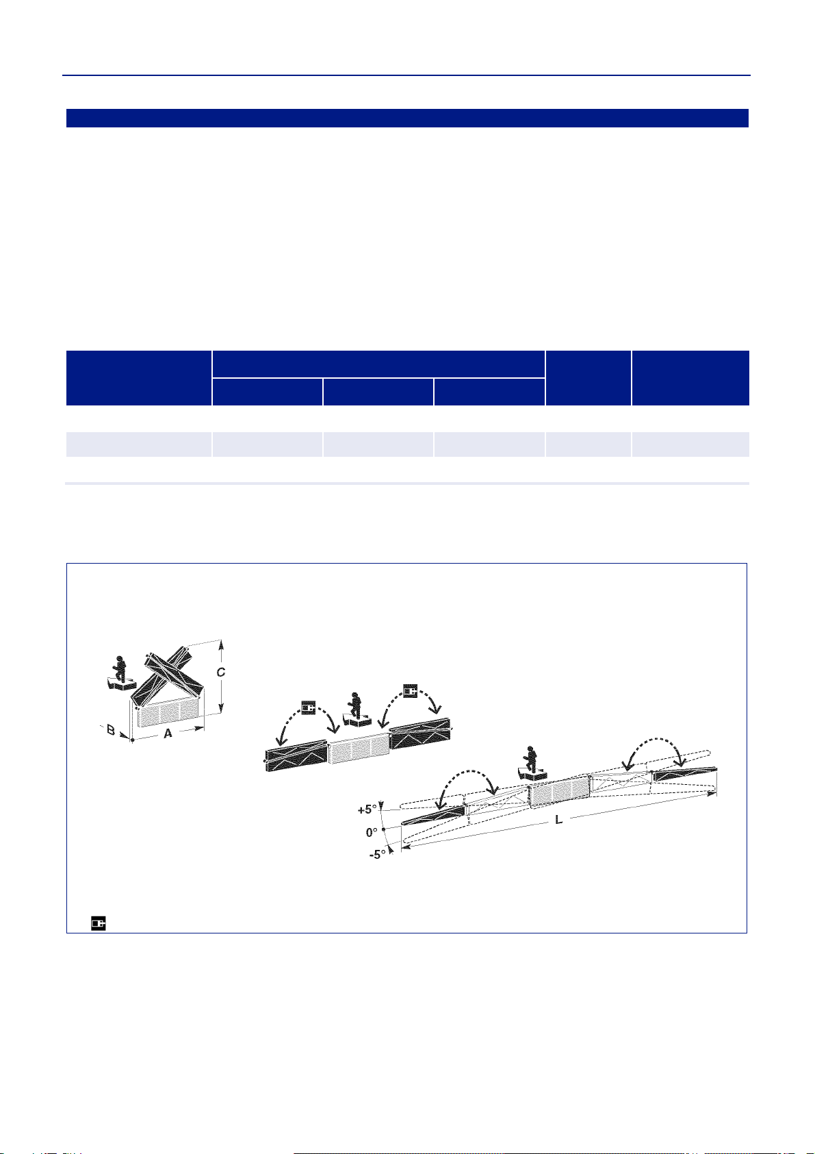
Technical specifications...........................2
Technical specification diagram....................2
Fittings on demand..................................2
Safety devices .........................................3
Safety distance diagram................................3
Identification plate position ......................4
Position of signals....................................4
INFORMATION ABOUT HANDLING
AND INSTALLATION..............................4
Handling instructions ...............................4
Packing and unpacking............................4
Loading and transportation......................5
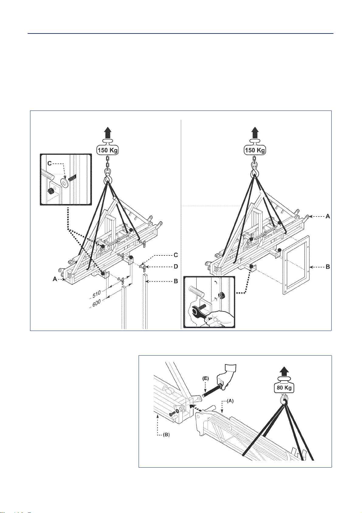
Handling and lifting..................................5
Installation instructions ............................5
Installation of disassembled parts............5
Equipment installation..............................6
Installation of arm ....................................6
Installation of the hydraulic system..........7
2-function hydraulic system (with electric
switch and control panel) ..............................8
Boom folding and unfolding...........................9
4-function hydraulic system (with electric
switch and control panel) ............................10
Boom folding and unfolding.........................11
4-function hydraulic system (with double
effect solenoid valves).................................12
Boom folding and unfolding.........................13
Installation of line filters (if required)
and jets..................................................14
Number of jets on each boom section...15
Jet number diagram for each boom
section (500 mm pitch)................................16
Installation of water hoses.....................16
5-supply water connection diagram ............18
Installation of rear light kit .....................19
Installation of the locking piston
(on request)........................................... 20
INFORMATION ABOUT
ADJUSTMENTS................................... 21
Instructions for adjustments..................21
Adjustment of the swinging sliding
shoes.....................................................21
Adjustment of the automatic blocking
device....................................................21
Adjustment of arm alignment ................22
Boom folding support adjustment..........23
INFORMATION ABOUT USE............... 23
Recommendations for use with
self-levelling device automatic locking..23
Recommendations for use with
self-levelling device hydraulic locking ... 24
Boom folding and unfolding...................25
Adjustment of tilt....................................25
Adjust the hydraulic locking device.......26
INFORMATION ABOUT
MAINTENANCE....................................27
Maintenance schedule table .................27
Lubrication points diagram.................... 28
Cleaning nozzles................................... 28
Long period of inactivity ........................29
TROUBLESHOOTING.......................... 29
Troubles, causes, remedies..................29
INFORMATION ABOUT
REPLACEMENTS ................................31
Replacement of spring and terminal
joint pin.................................................. 31
Replacement of corrector of position
spring ....................................................32
Disposing of the equipment...................32
Spraying boom
user manual
Serial number Edition 2
07 - 2013
Booklet
9

2330102.fm
- 2 -
English (translated from the original language) user manual
Spraying boom 9Booklet
TECHNICAL INFORMATION
EQUIPMENT GENERAL DESCRIPTION
The spraying boom, from now on called equipment,
wasdesignedand builttobe installed on amachinefor
spraying chemical products on tilled land and/or
products.
It is to be put on the height adjustment device and on
the self-levelling device so that it remains perfectly
parallel with the ground, even in the event the ground
is uneven..
The equipment is divided into folding boom sections in
order to adapt it to the spraying width and so as to re-
duce the space occupied during transfer.
TECHNICAL SPECIFICATIONS
(*) Boom with self-levelling devices on maximum configuration.
Technical specification diagram
FITTINGS ON DEMAND
Integral protection kit that protects nozzles from im-
pacts (ground, plants, etc.). Self-levelling device hydraulic locking; as an alterna-
tive to the automatic locking, it blocks the equipment
swinging.
Width (m) L Size (*) Weight
(kg) Qty. Jets
(500 mm)
A mm B mm C mm
12 2450 500 2420 290 24
12,5 2450 500 2420 292 25
15 2520 500 2900 315 30
233001001
Hydraulic Drive

2330102.fm
Spraying boom
- 3 -
English (translated from the original language) user manual
9Booklet
SAFETY DEVICES
Stop valve (in case of hydraulic tilt): itallowsto stop
movements of the various boom sections during use
and/or transport of the equipment and to prevent acci-
dental movements in the event of an hydraulic hose
failure.
Extension articulation: to allow the end of the exten-
sion to turn so as to get past obstacles. In order to get
past the obstacle without damaging the equipment, it
is necessary to keep a distance higher than the value
(D) given in the table.
12 65,4
12,5 6,25 5,63
15 7,5 6,8
Safety distance table
Safety distance diagram
Self-levelling device locking device
(A): it locks the equipment swinging in
the following steps.
- Transportation
-Boom folding and unfolding
- Boom folding on one side in order to
avoid an obstacle
- Boom use with only one side
unfolded
- Prolonged stopover or machine out
of use
Locking pin (B) (only for automatic
locking): it locks the self-levelling
device when the equipment is trans-
ferred.
Width (m)
LWidth
L1
Safety
distance
D
233001002
extension articulation extension articulation
B
A
A
A
HYDRAULIC LOCKING
AUTOMATIC LOCKING
233010046-00

2330102.fm
- 4 -
English (translated from the original language) user manual
Spraying boom 9Booklet
IDENTIFICATION PLATE POSITION
Thefigurepointsoutthepositionsofthe
identification plates of the components.
POSITION OF SIGNALS
The figure shows the location of all
safety plates, while their meaning is ex-
plained in booklet 1. The plates (Aand
B) supplied with the manual have to be
placed inside the tractor cab, in a visi-
ble position.
INFORMATION ABOUT HANDLING AND INSTALLATION
HANDLING INSTRUCTIONS
Comply with the information provided by the manufac-
turer, found on the equipment and in the instruction manual, when carrying out handling and loading oper-
ations.
PACKING AND UNPACKING
- The equipment is to be placed on a loading plat-
form, protected and adequately secured. To make
trans- port easier, it can be shipped with several
components disassembled.
- When unpacking, check that all the components
are intact and in the exact quantities.
- The packing material is to be disposed of properly,
in observance of the laws in force.
233001003.TIF
233001004.TIF

2330102.fm
Spraying boom
- 5 -
English (translated from the original language) user manual
9Booklet
LOADING AND TRANSPORTATION
Depending on the destination, loading
and transport can be carried out with
different means. The diagram shows
the most commonly used solutions.
Secure the means properly during
transportation in order to prevent
untimely shifting.
HANDLING AND LIFTING
The equipment can be handled with a
lifting device with forks or hooks having
a sufficient capacity. Position the lifting
device as shown in the figure. Avoid
sudden manoeuvres.
Danger - Warning
Lifting and handling operations must
be carried out by using appropriate
means and by skilled staff specialized
in this kind of manoeuvres.
INSTALLATION INSTRUCTIONS
Whoever performs the installation must prepare satis-
factory safety conditions in advance in order to ensure
their own safety and that of the operators involved.
INSTALLATION OF DISASSEMBLED PARTS
Follow the instructions given below so as to install and
assemble the spraying boom properly.
233001005.TIF
233001006.TIF

2330102.fm
- 6 -
English (translated from the original language) user manual
Spraying boom 9Booklet
EQUIPMENT INSTALLATION
Proceed as follows:
1 - Insert fastening plates (D) into guides (B).
2 - Insert nylon washers (C) into the screws outside
guides (B).
3 - Lift the middle frame (A) of the boom already
mounted on the self-levelling device (see “Self-
levelling Device” booklet) and fasten it to the slid-
ing frame of the lifting device (B) or to the shock
absorber, if required.
INSTALLATION OF ARM
Proceed as follows:
1-Liftarm(A) and fasten it to central
frame (B) by means of its pins (E)
after lubricating the parts and their
seats.
233001007.TIF
Installation on a slide lifting device Installation on guide or parallelogram lifting
device
233001008.TIF

2330102.fm
Spraying boom
- 7 -
English (translated from the original language) user manual
9Booklet
2 - Remove the rod of cylinder(C) and
fasten it to arm (D) and tie-rod (E)
by means of pins (F).
3 - Install cable (G)as shown in the
figure.
4 - Install the opposite arm by follow-
ing the same instructions.
INSTALLATION OF THE HYDRAULIC SYSTEM
Proceed as follows:
1 - Connect the hoses to the cylinders
(see the hydraulic diagram).
Important
Donottightenthe unionstoomuchso
as to damage the sealing taper fit.
G
233010007-01
233001010.TIF

2330102.fm
- 8 -
English (translated from the original language) user manual
Spraying boom 9Booklet
2-function hydraulic system (with electric switch and control panel)
233001012.TIF
The control is performed from the control panel and is acti-
vated from the tractor’s driver’s seat.
The control panel must be installed in such a way that the
driver can use it easily.
Electric switch with control panel
How to use the controls
1 - Select the function by means of switches (E)
position 1 = Unfolding / folding of left arm
position 0 = Unfolding / folding of right arm
2 - Activate the selected function by means of lever (C) of
the tractor’s control unit
233010009

2330102.fm
Spraying boom
- 9 -
English (translated from the original language) user manual
9Booklet
Boom folding and unfolding
The figure indicates the procedure to follow when
unfolding and folding the boom. Please note: the two arms can be folded or
unfolded independently of each other.
233001013.TIF

2330102.fm
- 10 -
English (translated from the original language) user manual
Spraying boom 9Booklet
4-function hydraulic system (with electric switch and control panel)
E2 E1
E3
C
The control is performed from the control panel and is acti-
vated from the tractor’s driver’s seat.
The control panel must be installed in such a way that the
driver can use it easily.
Electric switch with control panel
How to use the controls
1 - Select the function by means of switches (E) and acti-
vate the selected function by means of lever (C) of the
tractor’s control unit.
-Boom locking
E1 pos. 0 / E2 pos. 0 / E3 pos. 0
-Correction of position
E1 pos. 1 / E2 pos. 0 / E3 pos. 0
-Unfolding / folding of left arm
E1 pos. 0 / E2 pos. 1 / E3 pos. 0
-Unfolding / folding of right arm
E1 pos. 0 / E2 pos. 0 / E3 pos. 1
233010041-00
233010043-00

2330102.fm
Spraying boom
- 11 -
English (translated from the original language) user manual
9Booklet
Boom folding and unfolding
The figure indicates the procedure to follow when un-
folding and folding the boom. Please note: the two arms can be folded or
unfolded independently of each other.
233001013.TIF

2330102.fm
- 12 -
English (translated from the original language) user manual
Spraying boom 9Booklet
4-function hydraulic system (with double effect solenoid valves)
233001012.TIF
CGA CONTROL BOARD
A) Unfolding of left arm
B) Unfolding of right arm
C) Lifting
D) Hydraulic tilt adjustment
E) Hydraulic locking
MÜLLER CONTROL BOARD
A) Unfolding of left arm
B) Unfolding of right arm
C) Lifting
D) Hydraulic tilt adjustment
E) Hydraulic locking
A
C
B
D
A
C
B
E
233010042-00
D
E
This manual suits for next models
2
Table of contents
Other Croplands Paint Sprayer manuals

Croplands
Croplands WEED-IT User manual

Croplands
Croplands Quantum Mist Smart Spray QM-420 User manual

Croplands
Croplands GEX Series User manual

Croplands
Croplands Quantum Mist Smart Spray QM-420 User manual

Croplands
Croplands PEGASUS WEED-IT 4000 User manual

Croplands
Croplands RSRL3-100RC REEL User manual

Croplands
Croplands Pinto 2000 User manual

Croplands
Croplands AgriPak LA300 User manual

Croplands
Croplands CROPPAK US200F User manual