Croplands Quantum Mist Smart Spray QM-420 User manual

1
WWW.CROPLANDS.COM.AU
HT-OMSMART-A
INCORPORATING QM420 SPRAY FANS AND RECAPTURE SYSTEM
QUANTUM MIST
SMART SPRAYER
OPERATORS MANUAL
STOP
BEFORE COMMENCING
operation, ENSURE you read
& understand this manual, its
contents, and any additional
information supplied.

HT-OMSMART-A
2
INTRODUCTION | GENERAL MANAGER’S WELCOME
Dear Customer
Congratulations on the purchase of your new Croplands Sprayer.
Croplands have been in the business of building sprayer
equipment since 1972. For over 48 years we have been
supplying sprayers to farmers, contractors, growers and all
our customers involved in growing crops and in the control of
pests and diseases.
Croplands is a wholly owned subsidiary of Nufarm Ltd, the
largest supplier of crop protection chemicals for Australasia,
and one of the fastest growing global suppliers world-wide.
At Croplands, we pride ourselves on our commitment to
supplying machinery that is at the forefront of the industry’s
needs. We believe we can back up our products and through
constant research and development, bring to you the best
equipment you can find.
We welcome any feedback from you about our equipment.
On the back cover you will find our contact details, and locations
where our staff can be reached during business hours. After
hours, you can email us and expect a reply the following morning.
Please read this manual in its entirety before you operate your
sprayer. This will ensure you have a trouble free start up.
We trust you will get years of good use from your Croplands
Sprayer.
Yours Sincerely
Sean Mulvaney
General Manager
Sean Mulvaney
General Manager
Croplands has taken steps to ensure this operator’s manual is as current and as accurate as possible. Due to the ever-changing markets of cropping and farming, Croplands
is constantly striving to be at the forefront of innovation and technology. While the information in this manual is considered accurate at the time of writing, Croplands reserves
the right to change this information without notice. Croplands will not accept liability for any inaccuracy in this publication, or changes forthwith.

3
CONTENTS
SECTION 1
IMPORTANT INFORMATION
About this manual 4
Terminology 4
Before Operating Your Sprayer 4
Warranty Policy 5
SECTION 2
SAFETY
Safety first 7
Safety signs and decals 7
SECTION 3
PRODUCT IDENTIFICATION,
SHIPPING & SPECIFICATION
Product identification 8
Shipping information 8
General specification 9
SECTION 4
PRODUCT FEATURES /FAMILIARISATION
Quantum Mist QM-420 Spray fan 12
Fan frames, boom arms & tie rods 14
Hydraulic system 15
Spray pump 17
Fusion controller & connection 17
Windcomp hydraulics 19
Liquid system overview 20
Tanks & suction plumbing 20
Pump & pressure plumbing 22
Tiered spraying 24
SECTION 5
PREOPERATION
Safety first 28
Hook up 28
Fit & setup fusion controller to the tractor 31
Setup spray pressure 36
Set-up the booms 38
Set-up the Spray fans 41
Confirming fan functionality 42
Pre Operation Checklist 43
SECTION 6
SPRAY OPERATIONS
Safety first 45
Filters 45
Filling the sprayer 46
Setting sprayer pressure 46
Agitation 47
Mixing basket 47
Chemical probe 48
Calculate water & chemical quantities 49
Proceed to spray 50
Flushing 51
Tank and equipment cleaning 52
SECTION 7
SPRAYING INFORMATION
Spraywise 55
Calibration 55
Flowmeter calibration 56
Step 1 - ensure equipment is in good working order 56
Step 2 - determining the actual speed of travel 58
Step 3 - determine spraying volume required 58
Step 4 - determine sprayer configuration 58
Step 5 - determine the ideal spray pressure 59
Step 6 - determine & select correct nozzles 59
Step 7 - fit & test selected nozzles 60
Step 8 - calculate the actual application rate 60
Step 9 - if the tested rate is unsatisfactory 61
Step 10 - coverage assessment 62
Step 11 - add the correct amount of chemical to the tank 62
Step 12 - record all data for future reference 63
Calibration work sheet 64
SECTION 8
QUANTUM MIST / SMART SPRAY
RECAPTURE SYSTEM 68
SECTION 9
LUBRICATION & MAINTENANCE 74
SECTION 10
TROUBLESHOOTING 78
SECTION 11
ASSEMBLY DRAWINGS, PARTS &
SCHEMATICS 81

HT-OMSMART-A
4
SECTION 1
IMPORTANT INFORMATION
ABOUT THIS MANUAL
This manual provides assembly, setting up, operating and
maintenance instructions for the Croplands (Quantum Mist)
SMART SPRAYER.
In addition to this manual, the sprayer will be delivered
with the General Safety Manual (GP-SAFE-A), Fusion
Controller Manual (HT-FUSION-A) and Micro Power Pack
Manual (HT-OMMICRO-A). For details not covered by
this Guide or the Quantum Mist Manual, please contact
Technical Support.
Some features explained in this manual may not be
installed on your sprayer.
Please pass on this manual with the sprayer at the time of
resale for usage by the new owner.
This manual, HT-OMSMART-A, was first published in
September 2020.
Check online as there may be more recent revisions of
this manual.
TERMINOLOGY
These terms/symbols used throughout
this manual:
NOTE
This Note sign is in place to convey useful
information and will help you to identify
the best possible way to operate the
machine.
CAUTION
This Caution sign shows the potential
for an incident. An incident may include
damage to the machine itself, or possible
injury to the operator.
WARNING
This warning sign shows the potential for
risk or injury and highlights the need for
steps to be taken to protect one’s safety.
DANGER
This Danger sign will be used in areas where
the highest risk is present. Always read the
information on these signs and ensure you
are taking steps to prevent risk or injury.
BEFORE OPERATING YOUR SPRAYER
Before attempting to use your sprayer, make sure you
read all Operator Manuals for this sprayer including but
not limited to:
This Operator’s Manual, and all other supplied
manuals for items such as Micro Power Pack, Pumps,
PTO etc.
And properly understand:
• All Safety Issues.
• Assembly & Installation instructions.
• Calibration of the sprayer.
• Sprayer Operation.
• Sprayer Maintenance.
DANGER
!
Probability of death or serious
injury if an accident occurs
WARNING
!
To stress potential dangers and the
importance of personal safety.
CAUTION
!
To highlight potential injury or
machinery damage.
NOTE
To convey useful operating information.

5
SECTION 1
IMPORTANT INFORMATION
WARRANTY POLICY
Each sprayer will be delivered with a
Warranty & Pre-Delivery Booklet which
includes:
• the Sprayer’s unique serial number,
• the Sprayer’s specification sheet,
• a pre-delivery checklist and
• outlines the Croplands Warranty policy.
Always contact your Croplands Dealer first
and foremost for warranty matters.
NOTE
For full conditions of warranty and warranty
policy, please see the Warranty & Pre-Delivery
booklet provided with this sprayer.

HT-OMSMART-A
6
SECTION 2
SAFETY
SAFETY FIRST
Please read and understand all supplied manuals,
guides and safety decals before operating this
sprayer. This includes the Croplands Operators
Safety Manual – as pictured here.
This manual is available on the Croplands Web site,
or for printed versions contact Croplands customer
support and ask for part number GP-SAFE-A (or later
version if available).
OPERATORS
SAFETY
MANUAL www.croplands.com.au
STOP
BEFORE COMMENCING
operation, ENSURE you read
& understand this manual, its
contents, and any additional
information supplied.
GP-SAFE-A
STOP
BEFORE COMMENCING
operation, ENSURE you read
& understand this manual, its
contents, and any additional
information supplied.

7
SECTION 2
SAFETY
SAFETY SIGNS AND DECALS
All signs and decals for sprayer safety and operation must be maintained in good order and replaced if damaged or missing.
Most Croplands labels have a part number printed on the decal to aid identification and replacement.
Some examples are shown below.
Part No: XD-122V
Part No: XD-194
Part No: XD -195
Part No: XD -125V
Part No: XD -126V
Part No: XD -127V
Part No: XD -123
WARNING
!
1. Read your operators manual thoroughly before
operating the srayer.
2. Inspect hoses, connections and nozzles daily.
3. Clean filters regularly.
4. Always follow correct maintenance schedules
outlined in operator’s manuals.
5. Always read chemical manufacturers labels before use.
6. Always observe all warnings on chemical products.
7. Regularly check all nuts and bolts are tight.
8. Always wear rubber gloves and wash sprayer down
before doing any repair or maintenance work.
9. Do not ride on sprayer when moving.
10.Keep clear of moving parts when sprayer is operating.
11. Always keep guards in place when sprayer is operating.
12. Be sure tank lid is closed before operating basket
mixing facility.
13. Stand well clear of sprayer when operating.
14. Do not disconnect hoses, nozzles or filters while
sprayer is operating.
FAILURE TO FOLLOW THE ABOVE INSTRUCTIONS
MAY RESULT IN SERIOUS INJURY OR DEATH.
Croplands Equipment Pty Ltd XD-123MS
SAFETY INSTRUCTIONS

HT-OMSMART-A
8
SECTION 3
PRODUCT IDENTIFICATION, SHIPPING & SPECIFICATION
PRODUCT IDENTIFICATION
Always use the serial number of the Sprayer when
requesting service information or when ordering parts.
Early or later models (identification made by serial number)
may use different parts, or it may be necessary to use a
different procedure for specific service operations.
The serial numbers of all controllers, pumps etc should also
be recorded for future reference.
SHIPPING INFORMATION
All provided tie down points (and more) should be used to
help secure the sprayer for transporting.
Note serial number plate in the attached image.
Weights & Dimensions
The Croplands Smart Sprayer is available in 2000, 3000
and 4000 litre versions, all feature the QM-420 Spray
fans mounted in fan frames. Recapture screens and Micro
Power Packs are optional.
Maximum heights can vary depending on tyres used,
and ranges from 3.1m to 3.2m with 3.17m being the
most common (top of inner arm). Terracing versions are
3.80m high.
Maximum lengths from rear of the fan frames to the ball
joint of the Micro Power Pack (much the same position as a
normal towbar) are:
2000 Lt = 4450mm (5150mm with Micro Power Pack)
3000 Lt = 4700mm (5400mm with Micro Power Pack)
4000 Lt = 5200mm (5900mm with Micro Power Pack)
Micro Power Pack (from centre of sprayer connection ball
joint to linkage pickup points) is 700mm long.
Maximum widths, parked, from outside edge of the leaf
guards will vary depending on the boom width being
used – set at 2.5m row width the narrowest parked width
is 2200mm, and with the boom extended to the maximum
row width, the narrowest parked width is 2600mm.
Wide tower versions (depending on boom width and
position of the parking bracket), the maximum width is
2990mm wide.
Weights (not including recapture)
4000 Lt with Micro Power Pack = tba
3000 Lt with Micro Power Pack = 2583 kg empty
2000 Lt with Micro Power Pack = tba
Weight of Micro Power Pack = 190 kg
+/- 10 kg
Weight of Inner Recapture = 108 kg (pair)
Screens including Awning + external hardware & hoses
Weight of Boom Recapture = 124 kg (pair)
Screens including Awning + external hardware & hoses

9
SECTION 3
PRODUCT IDENTIFICATION, SHIPPING & SPECIFICATION
GENERAL SPECIFICATION
The SMART Sprayer is Croplands premium vineyard sprayer
that comes in double row and triple row configurations with
optional Recapture / Drift Reduction System.
The Quantum Mist™ system uses a combination of
individual hydraulically driven Spray fans with 5-blade
fans to give the maximum possible spray coverage in
grapes and dwarf tree crops.
All Smart Sprayers feature the Fusion Control system which
allows for full electric over hydraulic control for many of
the Smart Sprayer features.
For more detailed specification, see Section 4,
Product Features / Familiarisation
Controls
The Fusion controller with integrated joystick is used to
control all hydraulic (fan and boom) and spray functions.
Tank Sizes
2000, 3000 and 4000 litre tank options are available
and are constructed of impact resistant polyethylene and
UV stabilized. Each tank has an incorporated flushing tank
and a calibrated sight tube for filling level indication.
All main tanks drain completely via a large drain valve
and sump.
Chemical Handling
Quick fill (camlock) system and chemical suction probe
standard on all models.
Filtration
Lid-strainers & chemical mixing baskets are standard on all
models. Large suction filter, self-cleaning pressure
filter fitted.
Recapture system (when fitted) also incorporates inline filters.
Pumps
All Smart Sprayers are fitted with an Annovi Reverberi
positive displacement diaphragm pumps with a capacity of
165 to 250 L/min - depending on the sprayer model.
A heavy duty PTO shaft is supplied to drive the pump. This
will be supplied to suit the drawbar fitted.
Hydraulic driven pumps (in lieu of PTO) are also an option
when a Micro Power Pack is fitted to the sprayer.
Agitation
The agitation system is driven by the pump via twin supa-
flow venturi tank agitators & bypass agitation.
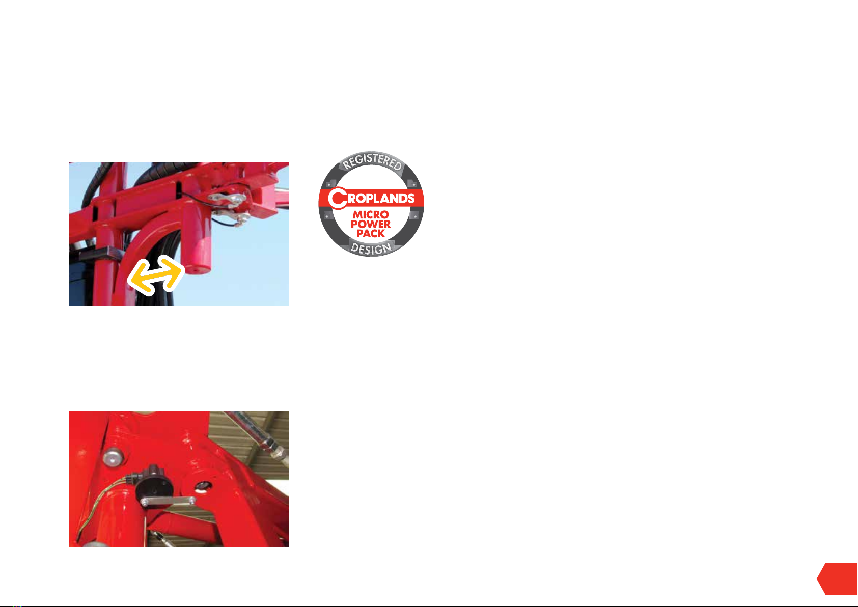
Hydraulic System
Hydraulic oil supply is from the tractor or Micro Power Pack.
The oil supply feeds to the main hydraulic control block
from which the oil is distributed to the hydraulically driven
fans and boom functions. The block also includes the main
pressure relief valve, anti-cavitation valve, soft-start and
test ports (pressure and return).
All models are fitted with a hydraulic oil radiator with
thermostat switching of an electric fan cooler.
Micro Power Pack
Supplied as standard on all 18 x fan models,, optional for
12 and 8 fan models, the Micro Power Pack is a compact,
independent oil supply system incorporated into a 3
point linkage, self-steering drawbar. Driven by the tractor
PTO shaft, the Micro Power Pack is available in single or
dual pump configuration depending on Sprayer model
specifications.
See separate manual for this option.
QM-420 Spray fans
The new QM-420 Spray fans “Fans”, comprised of
a Polyethylene Rotomoulded cowling which includes
mounting points on either side, into which there are
installed dual spray rings, front and rear safety guards and
drive body & fan.
The 5-blade 420mm diameter fan has been designed for
maximum air efficiency in the agricultural environment with
excellent characteristics for canopy spraying.
The fans are hydraulically driven by a case drained 6.5cc
or 9.8cc motor, driving via a double bearing “drive body”
and shaft with well proven rubber coupling to smoothly
drive the fan.
Nozzles
Each Spray fan comes with 2 spray rings with 5 nozzles
per ring, for a total of 10 nozzles per fan. The nozzles
are used in a 3 tier system, with low, medium and high
volumes available.
QM-420
P
A
T
E
N
T
P
E
N
D
I
N
G

HT-OMSMART-A
10
SECTION 3
PRODUCT IDENTIFICATION, SHIPPING & SPECIFICATION
Standard nozzles are ALBUZ 80 degree ceramic hollow
cone nozzles (brown and yellow).
The feed to all spray rings is fitted with a “non-drip”
diaphragm check valve with integral stop cock.
Spray rate capability for the Quantum Mist™ Smart
Sprayer ranges from 150 to 2000+ L/ha depending on
nozzle options.
Boom & Fan Frame
Robust powder-coated, heavy duty steel booms support
the galvanized “fan frames”. Booms are position sensing
and can be hydraulically folded to most conventional row
widths required via the Fusion controller.
Spray fan orientation is controlled via a pull rod /
parallelogram unit so that the fans remain square to the
target and park flat against the sprayer for transport.
Rear/inner booms are manually adjusted.
All fan frames feature a breakaway system.
2-Row and 3-Row
Boom configuration for a two row sprayer is “normal”,
however the 2-Row, 2-Row with Recapture or 3-Row
systems uses the unique “Hanger” style mounting (as
shown) at the end of the boom arm.
Chassis
Hot-dipped galvanised full-length heavy-duty chassis with
self-tracking drawbar, slide-out step & jockey stand.
Suspension
Walking beam tandem axle is fitted on all models.
Wheels & Tyres
11.5/80 x15.3 wheels with tubeless tyres are fitted as
standard. Flotation tyres available as options.
Recapture System
An optional 2-row drift reduction & recapture system can
be fitted to a 2-row QM Smart Spray. This is ideally suited
to cooler climate vineyards.
The system is modular and can be removed if the benefit of
drift control or recovery is not required.
Captured “over-spray” is returned to the sprayer tank via a
venturi suction system.
Speed Sensors
Proximity sensors are used for Fan speed, Pump speed and
wheel (travel) speed.
Tractor required
Power required at the PTO on flat terrain:
• 2-row - 40 HP
• 3-row - 65 HP
• 3-row / 18 fan / 4000 Lt - 90 ~ 100 hp
If not using a Micro Power Pack, hydraulic oil required will
be dependent on sprayer model & configuration, ranging
from 36 to 108 litres per minute at pressures up to a
maximum of 2,750 psi.
Category 2 or 3 linkage connections required.
Factory Fitted Options
• Wide Tower – will be supplied for use in row widths
greater than 3.0 metres (3.3 - 3.75)
• Recapture System
• Nozzles- Albuz 60-degree nozzles can be used in
lieu of 80-degree.
ARAG 40-degree (ceramic hollow cone) nozzles are
recommended with Optional Recapture system.
• Micro Power Pack (standard on all 18 fan models)
• Flotation tyres (31 x 13.5 – 15”) – not compatible with
the 2,000 Lt model
• Electric brakes
• Light kit
• Terracing tower
• Bio oil (for Micro Power Pack)
• Atlas 100 GPS speed sensor
• NuPoint GPS tracking, mapping and data reporting system
Machine specifications are subject to change
without prior notification.

11
QUANTUM MIST QM420 SPRAY FAN “FAN” 12
FAN FRAMES, BOOM ARMS & TIE RODS 14
HYDRAULIC SYSTEM 15
SPRAY PUMP 17
FUSION CONTROLLER SYSTEM & CONNECTION 17
WINDCOMP HYDRAULICS 19
LIQUID SYSTEM OVERVIEW 20
TANKS & SUCTION PLUMBING 20
PUMP & PRESSURE PLUMBING 22
TIERED SPRAYING 24
SECTION 4
PRODUCT FEATURES / FAMILIARISATION

HT-OMSMART-A
12
SECTION 4
PRODUCT FEATURES / FAMILIARISATION
QUANTUM MIST QM420 SPRAY “FAN”
Standard on all QM Smart Spray models is the new
extremely efficient 420 mm diameter “QM-420” fan.
Fan / Cap / Cover
The robust 5 bladed fan also features a separate
moulded front cap designed to prevent the build-up of
detritus so common in other fans, and the same cap, with
the “knockout” removed, is used at the rear to further
streamline the airflow.
Drive Body
The drive body differs from the “original” and very reliable
QM-380 drive body in that it has a further 4 tapped holes
to accept the rear cover. Note the rear cover (which is
the same moulding as the front cap, with a knock out for
the hydraulic motor) has positions for 5 screws, but only
4 screws are used. The “5th screw” position aligns with a
casting cutaway for either a speed sensor or case drain
connection (see photo above and below).
Cowl Orientation / Speed Sensor / Case drain
The cowling should always be mounted with the cutaway
for speed sensor or case drain facing downwards (to
enable drainage). The case drain is there for the unlikely
event of blowing oil seals in the hydraulic motor.
Sprayers fitted with the WindComp feature will use 2
speed sensors (left and right).
Note the rear guard needs to be removed to fit or access
the speed sensor. Replace the guard once done.
Dual Spray Rings
The fan also features dual spray rings, with 5 nozzles
per ring. This allows unprecedented control over spray
coverage rates and droplet spectrums.
As supplied, it’s set up as a 3-tier system. The inner /
smaller diameter spray ring is fitted with a smaller (eg.
brown) nozzle, and the outer / larger diameter spray ring
is fitted with a larger (eg. yellow) nozzles.
• Inner spray ring only is Tier 1 / lowest volume rate.
• Outer spray ring only is Tier 2 / medium volume rate.
• Both spray rings together are Tier 3 / for high volume rate.
There are many other ways to use the dual ring system such
as using one of the rings for special purpose nozzles.
Hydraulic Drive
All QM-420 fans are driven by hydraulic motors built to
a special heavy-duty specification and with case drain
port. Most QM Smart Spray models are fitted with 6.5 cc
motors. In some instances (if required) 9.8 cc motors can
be used as an alternative.

13
SECTION 4
PRODUCT FEATURES / FAMILIARISATION
Fan Guards
The QM-420 must never be used without the front and rear
guards installed.
Operational limits
The nominated maximum operating speed of the fan is
3,000 rpm. Normal delivered maximum operating speed
of 2,500 rpm. Exceptions apply.
DANGER, Stay well away from rotating fans.
Whilst the front (downwind) side may appear to be the
more dangerous side, it’s the back side that holds greater
danger as it can suddenly suck body parts or objects in.
Fan Frame Mounting
Each Spray fan is mounted via dual M12 brass inserts
moulded into each side of the cowling.
The normal Spray fan mounting method is via special
stainless-steel clamps into the “Fan Frame”.
The bracket is reversible and can be used to adjust head
positioning (see more page 41).
Check Valve / stop cock / drain
The feed to each spray ring is fitted with a “non-drip”
diaphragm check valve with integral stop cock which allows
individual spray rings to be manually shut off as required.
Screw the red cap in for stop, out for normal diaphragm
“non-drip”. Each spray ring has a draining / flush tap on
the exit.
FAN FRAMES, BOOM ARMS & TIE RODS
Fan Frames
Mounting the fans into the fan
frames has many advantages,
including the ability to specify
exact positioning of fan heights
and angles. The fans remain
well protected and fixed until a
change is required.
Up to 3 fans can be installed in
each fan frame – with the lower
fan also using a leaf guard (not
shown here)….
More about setting up and
operating the fans (and
booms) in Section 5.
Boom Configurations
All QM Smart Spray models
use the same rear (inner row),
width adjustable booms arms
at the rear of the sprayer
(Photo 1), with individual
fan frames, connected via a
breakaway swivel head.
2-Row Sprayers also use individual fan frames, connected
via a breakaway swivel head at the end of the main boom
arms (Photo 2).
3-Row sprayers use the same main boom arms, but instead
of an individual fan frame at the end of the boom, a “Twin
Hanger” is used to support a pair of fan frames at the end
of the main boom arms. (Photo 3). One set of fans pointing

HT-OMSMART-A
14
SECTION 4
PRODUCT FEATURES / FAMILIARISATION
inwards, the other set pointing outwards). A different
“Hanger” is used for 2-Row + Recapture.
A parallelogram system via an adjustable push – pull rod
keeps the fans pointing towards the canopy regardless of
the boom arm position from parked through to fully open.
In this way it’s possible to adjust boom (row) width by
rotating the boom.
Controlling the boom position and hence row width is via
the Fusion control system.
The main boom arm is also adjustable for length (Photo 4),
nominally suiting row widths from 2.5 to 3.4 metres via is a
series of adjustment holes in both the inner slide of the main
boom and also the pull rod. More details in Section 5.
Each fan frame is connected to the boom arm or “Hanger”
via a Swivel Head which incorporates the ability to
breakaway by about 45 degrees.
All swivel heads and connections use bushes which are
best used dry as grease will attract dust and dirt.
Whenever the Hanger system is used, the individual frames
are connected at the bottom, via a tie rod to ensure both
frames breakaway together (Photo 5).
Main Tower options
The standard Tower is supplied for use in vineyards with
row widths from 2.5 to 3.0 metres. Whilst it’s possible to
spray wider row widths, turning with the fans in the parked
position can become an issue (especially the 3
row versions).
Photo 1
Photo 2
Photo 3
Photo 4
Photo 5

15
SECTION 4
PRODUCT FEATURES / FAMILIARISATION
The (350mm each side) Wide Tower option (Photo 6) is the
supplied option for rows of 3.3m and above.
Boom Position Sensor
Each of the 2 main booms uses a boom position sensor,
shown here (Photo 7). These boom position sensors have
been factory calibrated to measure the booms working
width. This allows varying row widths to be set from the
cab via the Fusion controller.
HYDRAULIC SYSTEM
The Smart Sprayer using Fusion
control employs quite different
hydraulics from the Croplands
“Classic” Quantum Mist Sprayer.
The key difference is that each
fan frame, be it 2 or 3 fans
per frame, is its own separate
hydraulic circuit **.
Assuming sufficient oil supply,
this enables all fans to be run
at (or near) maximum speed
whilst keeping (relatively) low
pressures and temperatures.
Troubleshooting is also easier.
** Note in some markets
(smaller tractors / not requiring a
Micro Power Pack), the plumbing
is more “traditional” using circuits
of 4 or 6 fans.
For more details refer to the oil
flow schematic.
Each circuit connects to a specially developed “Fusion”
hydraulic block. All hydraulic boom functions, such as
boom fold cylinders are also connected to the same block.
Therefore, the operation of all functions connected to
the main block are controlled by the Fusion controller
(and joystick).
Note, to open and close boom arms require the Fusion
controller and hydraulics to be activated.
Micro Power Pack
Most of the larger Quantum Mist Smart Sprayers will
be equipped with the Micro Power Pack in one of 2
configurations, sized as is appropriate for your sprayer.
• Single pump or
• Dual pump.
There is a separate manual for the Micro Power Pack,
HT-OMMICRO-A, first published in August 2020.
Safety; Always be aware of the PTO shaft.
Photo 7
Photo 6

HT-OMSMART-A
16
SECTION 4
PRODUCT FEATURES / FAMILIARISATION
Oil Supply
There are three main options to supply hydraulic oil.
1. The preferred option is for oil supply via the PTO driven,
single pump, Micro Power Pack (see separate
manual), with the AR product (spray) pump driven via a
separate tractor remote. This is the simplest most reliable
and maximum performance setup. The most common
Micro Power Pack single pumps are 48, 56 or 74cc.
2. As above (Micro Power Pack) but using a dual
pump, with the smaller pump driving the AR product
(spray) pump. In some cases, this will limit maximum
fan performance. The most common pump sizes are
56/24cc, 48/32cc or 48/24cc.
3. Oil supply from Tractor hydraulics only. This is the
most economical option and is satisfactory for smaller
sprayers (2 row 8 fans or 12 fans). Note: very few
tractors will have sufficient oil flow (and pressure) for the
larger sprayers.
Oil Cooler
All Smart sprayers are fitted with a fan forced oil cooler.
The fan is thermostat controlled, switching in at around
50 degrees C.
The Fusion system requires a separate wiring loom, direct
from power source (tractor battery) to power the fan, part
CHLOOM/AC
WindComp
Wind Comp (wind compensation via independent Left/
Right fan speed control) is a feature made possible by the
new “Fusion” hydraulic system. The fans facing left or right
sides can be run independent of each other, at different
speeds. This is ideal for combating cross winds or spraying
in exposed / challenging conditions.
Refer “Fusion Controller Manual” for more
details on Wind Compensation
SPRAY PUMP
AR Pump
Smart Sprayers are fitted with an Annovi Reverberi positive
displacement diaphragm pumps with a capacity of 165 or
250 L/min - depending on the sprayer model.
When a Micro Power Pack is fitted to the sprayer, the AR
pump is driven by a hydraulic motor which is (preferably)
connected to the tractor remotes (yellow arrow below)
or via a secondary (dual) pump as a part of the Micro
Power Pack (blue arrow right) – note the use of a separate
manifold used to set and control the pump speed.

17
SECTION 4
PRODUCT FEATURES / FAMILIARISATION
For 18 x fan sprayer models the AR pump must to be
connected to tractor hydraulics.
In sprayer models without a Micro Power Pack the pump is
mounted to a 2 point or 3 point linkage self-steer drawbar
and driven by a heavy duty PTO shaft. 3 point linkage
pictured below.
FUSION CONTROLLER & CONNECTION
Quantum Mist Smart Sprayers come equipped with the
Fusion Controller. The first truly intuitive controller designed
for viticulture.
An Integrated joystick is used to control all sprayer and
hydraulic functions.
CANBUS technology.
It allows for full electric over hydraulic control which allows
for many of the new Smart Sprayer features.
From battery to cab is a power loom (MT90LOOM/
PWR), and thereafter is the Fusion loom (CHLOOM-
FUSION) which connects to the ECU module (mounted
at the front of the sprayer).
The front end of the loom has 3 connections for:
• Console (12 pin)
• Joystick (6 pin)
• Updating port (4 pin) or optional Nupoint
Followed by a power lead which picks up the
MT90LOOM/PWR.
Behind the cab is a connection to break tractor from
sprayer – a handy way to make sure everything is off.
Note the section valves can draw a small current even with
the controller turned off.
At the sprayer the loom connects to the ECU Module with
2 large pins.
From here are connections for:
• Micro Power Pack (level switch)
• Pump speed (pump is powered by tractor remotes)
• Flow meter
• Proximity or GPS Speed Sensor
• Spray “dump” / by-pass valve
• Flow Meter
• Pressure Transducer
• Tank level (optional)

HT-OMSMART-A
18
SECTION 4
PRODUCT FEATURES / FAMILIARISATION
At the rear of the sprayers there are connections for …
• Section valves (8 Neg switching)
• Boom position sensors and boom fold control.
And
• Main hydraulic function block which has ..
o Fan speed sensors (2)
o Fan speed control (2)
o Hydraulic pressure (2)
o Dump
See schematics diagram for more detail.
Note the photo shows the main Fusion hydraulic block
(top), boom control manifold (middle) and 8 spray section
control valves (below) all installed in an (optional) control
box (with the lid removed). Note the orientation of blocks
will be different on sprayers without this box.
Photo below is 4 section valves / 2 row sprayer.
Note, in the photo’s above and left, the labels (as shown
below) have not yet been applied.
Refer to the separate Fusion Manual for more
information on operating the controller & system.
T2
LL
T1
LL
3 ROW
LEFT
T1
RR
T2
RR
3 ROW
RIGHT
T2
L
T1
L
T1
R
T2
R
2 ROW
LEFT - RIGHT

19
SECTION 4
PRODUCT FEATURES / FAMILIARISATION
WINDCOMP HYDRAULICS
Wind Comp (wind compensation via independent Left/
Right fan speed control) is a new feature made possible
by the new Fusion hydraulic system. The fans facing left or
right sides can be run independent of each other. This is
ideal for combating cross winds or spraying in exposed
/ challenging conditions. For example, instead of running
both sides of the sprayer at 2,200 rpm, with Wind Comp
it’s possible to increase fan speed against the wind to say
2,500 rpm, and on the downwind side the rpm will drop to
around 1,900 rpm.
For more detailed information refer to page 34
and in the Fusion Manual HT-OMFUSION-A.
Note the laws of physics still apply, if the maximum speed
is 2,500 rpm on all fans, it’s not possible to increase one
side to 2,800 and leave the other at 2,500.
Note in the photo, the coil circled (closest to the main
inlet / outlet at position (K), controls the fans that spray to
the right side, and the coil below controls the left facing
fans. Note in some applications the block is mounted with
position (K) to the bottom.
PTO Speed / Hydraulic Requirements
Due to the configuration of the hydraulic control block,
the PTO / Pump / Tractor (depending on how oil is being
supplied) needs to maintain a minimum output in order
to supply both sides of the fan circuits with the same
operating rpm. For example, if at PTO = 420 rpm and both
LH & RH fans are running at 2,400 rpm, as the PTO speed
reduces below the minimum, one side will maintain priority
and continue to run at 2,400 rpm and the other side will
drop away and run slower. This feature can be used to
determine best PTO speed to economically run the sprayer.
Recommended minimum PTO speed = 420 rpm
Note the actual minimum (at which point the LH and RH
fans differ) will change from sprayer to sprayer and is more
likely to be lower than 400 rpm.

HT-OMSMART-A
20
SECTION 4
PRODUCT FEATURES / FAMILIARISATION
LIQUID SYSTEM OVERVIEW
“Front End” Spray Controls
A. Pump (AR185 shown)
B. Hydraulic pump drive, including control manifold
C. Pressure manifold. This includes the manual master
pressure adjustment (knob) and red, manual flick taps
to control the suction probe, front & rear agitators and
the basket / powder mix
D. Pressure filter, includes pressure sensor
E. Pressure Regulator (Servo) & Dump valves.
F. Flow meter
G. Suction filter (from tank and into suction manifold
of the pump).
H. Chemical suction probe fitting
I. Quick fill connection
J. To Recapture system venturi.
TANKS & SUCTION PLUMBING
Smart Sprayer models feature three tanks, Main
(chemical), (fresh) Flushing and (fresh) Handwash for easy
operation, cleaning and safety.
All Main tanks are equipped with large lid and basket
filter. Plumbed to the filter basket is a Basket / Powder Mix
function activated via a tap from the pressure manifold.
All Flushing and Handwash tank lids should be clearly
labelled as WATER ONLY. Replacement labels are
available under the code XD-127V.
E
D
B
F
C
A
G
H
I
J
Other manuals for Quantum Mist Smart Spray QM-420
1
This manual suits for next models
2
Table of contents
Other Croplands Paint Sprayer manuals

Croplands
Croplands AgriPak LA300 User manual

Croplands
Croplands Pinto 2000 User manual

Croplands
Croplands CROPPAK US200F User manual

Croplands
Croplands RSRL3-100RC REEL User manual

Croplands
Croplands MHL12 User manual

Croplands
Croplands Quantum Mist Smart Spray QM-420 User manual

Croplands
Croplands PEGASUS WEED-IT 4000 User manual

Croplands
Croplands WEED-IT User manual

Croplands
Croplands GEX Series User manual