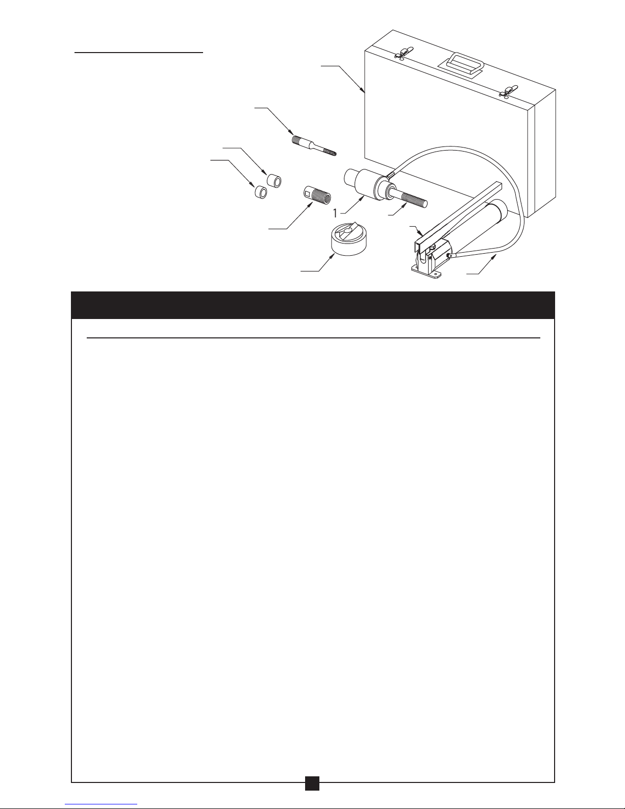
Current Tools 152 User manual

Current Tools™ Hydraulic Knockout Sets
CURRENT TOOLS • P. O. BOX 17026 GREENVILLE, SC 29606
800.230.5421 or 864-721-4230 • FAX 864-721-4232
www.currenttools.com
and
Model 152 PM – ½" to 2"
Model 154 PM – ½" to 4"
Model 152 – ½" to 2"
Model 154 – ½" to 4"
08/10 - REV. 3
Operating, Maintenance, Safety
and Parts Manual
This manual is free of charge. All personnel who operate or
service the Hydraulic Knockout Set should have a copy of this
manual and read and understand its contents. To request a copy,
call or write to the address below.
Read and understand this material before
operating the Hydraulic Knockout Set. Failure to
understand how to safely operate and service
this unit may result in serious injury or death.

Hazards or unsafe
p
ractices which, if not avoided, COULD result in serious
personal in
j
ur
y
or death
.
W
ARNIN
G
Hazards or unsafe
p
ractices which, if not avoided, COULD result in minor
personal in
j
ur
y
or propert
y
damage
.
CA
UTI
ON
Immediate hazards which, if not avoided, WILL result in serious
p
ersona
l
in
j
ur
y
or death
.
DAN
G
E
R
THIS SAFETY SYMBOL is used to call your attention to instructions
that concern your personal safety. It means: ATTENTION! BE AWARE!
THIS IS AN IMPORTANT SAFETY INSTRUCTION!
Read, understand, and follow these safety instructions. Failure to follow
these safet
y
instructions ma
y
result in in
j
ur
y
or death.
Safety Alert
Symbol
2
TABLE OF CONTENTS
Safety Alerts.............................................. 2
Safety Information....................................... 3-4
Specifications ............................................. 4
Operating Instructions.................................... 4-5
Set-Ups Diagram .......................................... 6
Components List .......................................... 7
Section View & Parts List — Model 1522 Ram . . . . . . . . . . . . . . . . . . 8
Specifications — Model 1521 Hand Pump. . . . . . . . . . . . . . . . . . . . . . 9
Operating Instructions — Model 1521 Hand Pump . . . . . . . . . . . . . . 9
Maintenance — Model 1521 Hand Pump . . . . . . . . . . . . . . . . . . . . . . 9
Exploded View — Model 1521 Hand Pump. . . . . . . . . . . . . . . . . . . . 10
Parts List — Model 1521 Hand Pump. . . . . . . . . . . . . . . . . . . . . . . . . 11
Repair Kit — Part No.1521-RPRKIT . . . . . . . . . . . . . . . . . . . . . . . . . . . 11
SAFETY ALERTS

W
ARNIN
G
WARNING
WARNING
WARNING
WARNING
WARNING
WARNING
WARNING
DANGER
WARNING
WARNING
This manual should be read and understood by all personnel who operate or
service this Hydraulic Knockout Set. Failure to understand how to safely
operate and service this unit could result in injury or death. This unit should
only be operated or serviced by qualified personnel.
RETAIN SAFETY INFORMATION
3
NEVER use the Knockout Set or any of its components near
live circuits.
ALWAYS stand to the side of the ram when punching. This
will help avoid injury should there be a component failure.
The model 1521 Hand Pump is pre-set at the factory to operate
at pressures up to 8,000 PSI. Do NOT connect any pump to the
Current Tools model 1522 Ram that will exceed 8,000 PSI. Doing
so may cause component failure which may result in injury or
death. Only use a hand or foot operated pump with the model
1522 Ram. Never operate the ram with an electric pump.
Be sure to support the ram while punching. An unsupported
ram could fall causing injury.
Do NOT continue to operate pump after the ram completes
the punch. Doing so will damage the ram and could cause
component failure resulting in serious injury or death.
If the ram motion stops before the punching process
is completed, Do NOT continue to operate the pump.
Release the pump pressure and disassemble the set-up
and determine the cause before continuing.
Hydraulic tools create tremendous pressures and hydraulic oil
can easily puncture skin. If your skin is pierced by oil you must
seek medical attention immediately! NEVER touch the hydraulic
hose or fittings while the unit is under pressure.
ALWAYS thread the punch COMPLETELY onto the draw stud
( or adapter ) to avoid thread failure. If the punch tightens before
it is completely threaded onto the draw stud, disassemble the
set-up and determine the cause. Then reassemble the set-up.
ALWAYS release the hydraulic pressure before removing
any hoses or before servicing any component of the
hydraulic system.
ONLY replace the hoses and fittings with Current Tools
replacement parts.
NEVER attempt to exceed the punching capacity of this
knockout set. Doing so may cause component failure and
possibly serious injury or death.
continued on next page . . .
IMPORTANT SAFETY INFORMATION
Follow ALL safety information provided by the manufacturer.

CAUTION
CAUTION
CAUTION
CAUTION
CAUTION
WARNING
WARNING
WARNING
WARNING
4
NEVER attempt to punch a hole through more than a single
layer of material. Doing so may cause component failure and
possibly serious injury or death.
NEVER use this knockout set or any of its components except
for its intended purpose.
Hand pressure is sufficient to activate the pump. NEVER
attempt to apply additional pressure to the pump handle.
The Model 1521 Hand Pump is designed for use ONLY with
Hydraulic Knockout Sets and Cable Cutters.
ALWAYS inspect every component of the punch set-up
including the ram, pump, fittings, punch, die, draw stud,
adapter, and spacer(s) before each use. Replace any worn
or defective parts with Current Tools replacement parts.
NEVER use dull punches.
NEVER use any component that has worn or damaged threads.
ALWAYS check to ensure all components are properly
assembled before punching.
New punches are sharp. Be careful when handling them.
ALWAYS wear safety glasses when punching.
BENDING
IMPORTANT SAFETY INFORMATION continued . . .
BENDING
continued on next page . . .
SPECIFICATIONS
Model No. 152 and 152PM 154 and 154PM
Overall Dimensions 41⁄8" x 101⁄2" x 17 3⁄4" 41⁄8" x 14" x 173⁄4"
Capacity 1⁄2" to 2”conduit size holes 1/2” thru 4” conduit size holes
Weight 25 lbs. 54 lbs.
The model 1521 Hydraulic Hand Pump has a maximum operating pressure of 8,000 PSI.
NOTE: All models are designed to punch a maximum of 10 gauge mild steel (.134 in. thick)
Current Tools™ Models 152PM and 154PM — Piece Makers™ — are designed to
split the slug into two pieces for easy removal from the die after punch completion.
OPERATING INSTRUCTIONS
1. Match the punch, die, draw stud, adapter ( if needed ) , and spacer(s)
as required for the size hole to be punched. ( See Figures 1a, 1b, 1c. )
2. After marking the hole location, drill a hole approximately 1⁄32" to 1⁄16"
larger than the draw stud or adapter being used.
NOTE: Alternate Method — Drill a 7⁄16" hole to accept the 3⁄8" adapter draw
stud (Part #1581) and use the 1⁄2" punch and die to increase the hole size to
accept the 3⁄4" draw stud (Part #1582). Then, if needed, use 1" punch and die
to increase the hole size to accept the 11⁄8" adapter.

W
ARNIN
G
ALWAYS thread the punch COMPLETELY onto the draw stud
(
or adapter
)
to avoi
d
thr
ead
f
a
il
u
r
e
. If the punch tightens before it is completel
y
threaded onto the draw
stud, disassemble the set-u
p
and determine the cause. Then reassemble the set-u
p.
5
W
ARNIN
G
•
DO NOT continue to o
p
erate the
p
um
p
after the ram com
p
letes the
p
unch. Doin
g
so will
dama
g
e the ram and could cause component failure resultin
g
in serious in
j
ur
y
or death
.
•
If the ram motion stops before the punchin
g
process is completed, DO NO
T
co
ntin
ue
t
o
o
p
erate the
p
um
p
. Release the
p
um
p
p
ressure and disassembl
e
the set-u
p
and determine
the cause before continuin
g.
•
Be sure to support the wei
g
ht of the ram while punchin
g
. An unsupported ram could fall
causing in
j
ur
y.
SPACER CHART
Punch & Die Size Spacers
1⁄2" SHORT (#1553)
3⁄4" thru 11⁄4" MEDIUM (#1554)
11⁄2" SHORT (#1553)- L
2" thru 4" No spacers
3. When using 3⁄4" through 3" punch and die, thread the end of the
3⁄4" draw stud (Part #1582) with the shortest thread length into the ram until
snug. (See Figure 1b. )
When using the 1⁄2" punch and die, thread the larger 3⁄4" end of the
3⁄8" adapter draw stud (Part #1581) directly into the ram until snug.
(See Figure 1a. )
When using the 31⁄2" and 4" punch and die, thread the 11⁄8" adapter
(Part #1552) over the 3⁄4" draw stud (Part #1582) until snug. The threaded
end of the 11⁄8" adapter should face away from the ram. (See Figure 1c. )
4. Determine spacer(s) needed (if any) and install. (See Spacer Chart below.)
5. Slide the die onto the draw stud with the open end of the die facing
away from the ram.
6. Place the draw stud through the hole you drilled in step 2. Then thread
the punch onto the draw stud (or adapter) with the cutting face toward
the material to be punched. Thread the punch onto the draw stud until
the punch, die and spacers are snug against the material.
7. Complete the punching process by activating the hand pump.
(See hand pump operating instructions on page 9.)
OPERATING INSTRUCTIONS continued . . .

6
PUNCH
MATERIAL
DIE
SHORT
SPACER
3/8"
ADAPTER
STUD
RAM
RAM 3/4" DRAW
STUD
SPACERS AS NEEDED
See SPACER CHART
Page 5 DIE
PUNCH
MATERIAL
RAM 3/4" DRAW
STUD DIE PUNCH
1-1/8"
ADAPTER
RAM WITH
3/8"
ADAPTER
STUD
SHORT
SPACER
1/2"
DIE 1/2"
PUNCH
3/8"
ADAPTER
STUD
3/4"
DRAW
STUD
RAM
PUNCH
DIE
RAM
DIE
PUNCH
3/4"
DRAW
STUD
1 1/8"
ADAPTER
THREADED
END
1/2"
PUNCH
& DIE
3/4"-3"
PUNCH
& DIE
3-1/2"
AND 4"
PUNCH
& DIE
MATERIAL
MATERIAL
MATERIAL
1A
SHORTEST
THREAD
LENGTH
SHORTEST
THREAD
LENGTH
1B
1C
FIGURE 1
SPACERS AS NEEDED
See SPACER CHART
Page 5
3 1/2" & 4" DIES REST
ON RAM SHOULDER
MATERIAL
SET UPS
EXPLODED VIEW COMPLETED VIEW

9
& 1
0
4
7
6
5
3
11
t
hr
u
36
8
1
2
7
COMPONENTS LIST
ITEM# CATALOG# DESCRIPTION #152 #152PM #154 #154PM
1⁄2" to 2" 1⁄2" to 2" 1⁄2" to 4" 1⁄2" to 4"
1 ...............1522 ................... Ram (Includes #2) .................. 1 .................. 1 ................. 1 ................. 1
2 ...............1582 ........................3⁄4" Draw Stud ......................1 ..................1 ................. 1 ................. 1
3 ...............1552 ......................... 11⁄8" Adapter ................................................................1 ................. 1
4 ...............1581 ................ 3⁄8" Adapter Draw Stud ...............1 ..................1 .................1 ................. 1
5 ...............1553 ....................Short Spacer – S ................. 1 .................. 1 ................. 1 ................. 1
6 ...............1554 .................Medium Spacer – M .............. 1 .................. 1 ................. 1 ................. 1
7 ...............1521 .................Hydraulic Hand Pump ...............1 ..................1 .................1 ................. 1
8 ...............1523 ................ 1⁄4" x 3' Hydraulic Hose ..............1 ..................1 .................1 ................. 1
9 ............1500-PC ... Plastic Carrying Case –1⁄2" to 2" Set ....1 ..................1 ......................................
10 ..............1501 .......Metal Carrying Case –1⁄2" to 4" Set ..............................................1 ................. 1
11 ..............1524 ................1⁄2" Piece Maker™ Punch ...................................1 ..................................... 1
12 ..............1525 .............................. 1⁄2" Die ............................1 ..................1 .................1 ................. 1
13 ..............1526 ................3⁄4" Piece Maker™ Punch ...................................1 ..................................... 1
14 ..............1527 .............................. 3⁄4" Die ............................1 ..................1 .................1 ................. 1
15 ..............1528 ................ 1" Piece Maker™ Punch ...................................1 ..................................... 1
16 ..............1529 .............................. 1" Die............................. 1 .................. 1 ................. 1 ................. 1
17 ..............1530 ...............11⁄4" Piece Maker™ Punch ..................................1 ..................................... 1
18 ..............1531 ............................. 11⁄4" Die ...........................1 ..................1 .................1 ................. 1
19 ..............1532 ...............11⁄2" Piece Maker™ Punch ..................................1 ..................................... 1
20 ..............1533 ............................. 11⁄2" Die ...........................1 ..................1 .................1 ................. 1
21 ..............1534 ................ 2" Piece Maker™ Punch ...................................1 ..................................... 1
22 ..............1535 .............................. 2" Die .............................1 .................. 1 ................. 1 ................. 1
23 ..............1560 ................... 1⁄2" Standard Punch .................1 ......................................1 ..................
24 ..............1561 ................... 3⁄4" Standard Punch .................1 ......................................1 ..................
25 ..............1562 ....................1" Standard Punch .................. 1 ...................................... 1 ..................
26 ..............1563 .................. 11⁄4" Standard Punch ................1 ......................................1 ..................
27 ..............1564 .................. 11⁄2" Standard Punch ................1 ......................................1 ..................
28 ..............1565 ....................2" Standard Punch .................. 1 ...................................... 1 ..................
29 ..............1566 ...........................21⁄2" Punch ..................................................................1 ................. 1
30 ..............1567 ............................. 21⁄2" Die ....................................................................1 ................. 1
31 ..............1568 ............................3" Punch ...................................................................1 ................. 1
32 ..............1569 .............................. 3" Die ...................................................................... 1 ................. 1
33 ..............1570 ...........................31⁄2" Punch ..................................................................1 ................. 1
34 ..............1571 ............................. 31⁄2" Die ....................................................................1 ................. 1
35 ..............1572 ............................4" Punch ...................................................................1 ................. 1
36 ..............1573 .............................. 4" Die...................................................................... 1 ................. 1
COMPONENTS
KNOCKOUT SET

1
6
2
3
4
5
7
8
9
10
SECTION VIEW
MODEL 1522 RAM
PARTS LIST — Model 1522 Ram
ITEM# PART# QTY DESCRIPTION
1 ............................ 1522-11 ............................1 ....................................... CYLINDER
2 ............................ 1522-12 ............................1 ......................................... PISTON
3 ............................. 1522-2 .............................1 ......................................... SPRING
4 ............................. 1522-4 .............................1 ............................................ CAP
*5 ............................. 1522-5 .............................1 ................................. RETAINING RING
6 ...............................1582 ..............................1 .................................. 3⁄4" DRAW STUD
*7 ............................. 1522-7 .............................1 ................................... BACK-UP RING
*8 ............................. 1522-8 .............................1 ..........................................O-RING
*9 ............................. 1522-9 .............................1 ..........................................O-RING
*10 ............................ 1522-10 ............................1 ................................... BACK-UP RING
8
* Included in Repair Kit Part Number 1522-RPR

9
BENDING
BENDING
BENDING
The Model 1521 Hand Pump is designed for use ONLY with H
y
draulic Knockout Sets and Cable Cutters.
WARNIN
G
Hand
p
ressure is sufficient to activate the
p
um
p
.
NEVER
attempt to appl
y
additional pressure to the pump handle
.
W
ARNIN
G
SPECIFICATIONS — MODEL 1521 HAND PUMP
Model No. 1521 Hand pump
Overall Dimensions 27⁄8" Wide x 3 7⁄8" Tall x 123⁄4" Long
Capacity 8,000 PSI max — .069 cu. in. of oil per stroke
Weight 4.5 lbs. (with oil)
Oil Capacity 16 cu. in.
MAINTENANCE
Oil Requirements: We recommend a high quality automatic transmission
fluid such as Shell DONAX TG or equivalent
Filling the Pump with Oil:
1. Secure the pump in a vise by clamping lightly onto the hex body with
the reservoir and end cap facing upward, and unscrew the end cap.
2. Remove the rubber plug located in the center of the reservoir follower,
and then remove the reservoir follower. Check the reservoir follower
O-ring and the rubber plug for damage or wear, and replace as needed.
3. Fill the reservoir until the oil level is 3⁄4" from the top.
4. Push the reservoir follower into the reservoir until oil begins to come
out of the hole.
5. To remove trapped air from the pump, turn the release knob clockwise to
the closed position and pump the handle 5 times. Slowly turn the release
knob counterclockwise while keeping light pressure with your finger over
the hole in the reservoir follower. This allows air to escape under your
finger and prevents ejecting oil. Repeat this procedure if needed.
6. Replace the rubber plug in the reservoir follower.
7. Remove and clean the felt vent located inside the reservoir end cap.
Then screw the reservoir end cap back onto the reservoir.
OPERATING INSTRUCTIONS
1. Turn knob clockwise.
2. Pump handle to activate
hand pump.
3. When operation is complete,
turn knob counter-clockwise.

6
24
SEE
EXPLODED
VIEW
2
29
5
16
17
2k 2g
13
3
2j
ITEM 2
EXPLODED
VIEW
2c
2h
2f
2e
2d
26
11
15 14
12
23
19
10
1
9
8
18
28
4
2b
2m
27
25
7
2a
20
22
21
10
MODEL 1521 HAND PUMP EXPLODED VIEW

11
BENDING
PARTS LIST — Model 1521 Hand Pump
ITEM # PART # QTY DESCRIPTION
1 ............................ 1521-1 .............................1 ...........................................BODY
2 ............................ 1521-2 .............................1 ..............................RELEASE ASSEMBLY
2a .......................... 1521-2a ............................1 .................................. RELEASE BODY
2b .......................... 1521-2b ...........................1 ..........................................SCREW
2c .......................... 1521-1d ...........................1 ........................................... BALL
2d .......................... 1521-2d ...........................1 .................................SPRING RELEASE
2e .......................... 1521-2e ............................1 ................................... BACK UP RING
2f ............................1521-2f ............................1 ..........................................O-RING
2g .......................... 1521-2g ..........................1 ..........................................O-RING
2h .......................... 1521-2h ...........................1 ..........................................O-RING
2j ............................1521-2j ............................1 ........................................ROLL PIN
2k .......................... 1521-2k ............................1 ......................................SET SCREW
2m .........................1521-2m ...........................1 ...........................................KNOB
3 ............................ 1521-3 ...........................1 ........................................... FOOT
4 ............................ 1521-4 .............................1 ................................ PISTON RETAINER
5 ............................ 1521-5 .............................1 .................................. PISTON DOWEL
6 ............................ 1521-6 .............................1 .................................... HANDLE LINK
7 ............................ 1521-7 .............................1 .........................................HANDLE
8 ............................ 1521-8 .............................1 .........................................SCREEN
9 ............................ 1521-9 .............................1 ................................SCREEN RETAINER
10 .......................... 1521-10 ..........................2 .................................... CHECK VALVE
11 .......................... 1521-11 ............................1 ...................................... RESERVOIR
12 .......................... 1521-12 ............................1 .................................... RELIEF VALVE
13 .......................... 1521-13 ............................1 ......................................SPRING PIN
14 .......................... 1521-14 ............................1 ..........................................O-RING
15 .......................... 1521-15 ............................1 ................................... BACK UP RING
16 .......................... 1521-16 ............................1 ................................... BACK UP RING
17 .......................... 1521-17 ............................1 ..........................................O-RING
18 .......................... 1521-18 ............................2 ..................................... HANDLE PIN
19 .......................... 1521-19 ............................1 ..........................................O-RING
20 .......................... 1521-20 ............................1 ..................................RESERVOIR CAP
21 .......................... 1521-1B ...........................1 ..................................RETAINING CLIP
22 .......................... 1521-1C ...........................1 .......................................FELT VENT
23 .......................... 1521-23 ............................1 ........................................... PLUG
24 .......................... 1521-1A ...........................2 ..........................................SCREW
25 .......................... 1521-25 ............................1 ...............................RESERVOIR PISTON
26 .......................... 1521-26 ............................1 ..........................................O-RING
27 .......................... 1521-27 ............................1 ................................... RUBBER PLUG
28 .......................... 1521-28 ............................4 ................................. RETAINING RING
29 .......................... 1521-29 ............................1 ........................................ROLL PIN
REPAIR KIT PART #1521-RPRKIT Contains the following:
14 .......................... 1521-14 ............................1 ..........................................O-RING
15 .......................... 1521-15 ............................1 ................................... BACK UP RING
16 .......................... 1521-16 ............................1 ................................... BACK UP RING
17 .......................... 1521-17 ............................1 ..........................................O-RING
19 .......................... 1521-19 ............................1 ..........................................O-RING
26 .......................... 1521-26 ............................1 ..........................................O-RING
27 .......................... 1521-27 ............................1 ................................... RUBBER PLUG
2e .......................... 1521-2e ............................1 ................................... BACK UP RING
2f ............................1521-2f ............................1 ..........................................O-RING
2g .......................... 1521-2g ...........................1 ..........................................O-RING
2h .......................... 1521-2h ...........................1 ..........................................O-RING
This manual suits for next models
3
Table of contents
Other Current Tools Power Tools manuals
Popular Power Tools manuals by other brands

DNIPRO M
DNIPRO M JS-110SF manual

Black & Decker
Black & Decker FireStorm FS300DP instruction manual

Electronica Technologies
Electronica Technologies EL700 manual

Metabo HPT
Metabo HPT FCJ 65V3 Handling instructions

Power Glide
Power Glide 60101211 Assembly and operating instructions

Wacker Neuson
Wacker Neuson PV 35A Operator's manual