5
WARNING
WARNING
WARNING
WARNING
WARNING
WARNING
WARNING
WARNING
WARNING
WARNING
Pulling Rope should be the only thing to contact the capstan.
NEVER let swivels, grips, etc. come in contact with the capstan.
Keep as much rope confined in conduit as possible. This will
help prevent injury should the rope break and whip violently.
Rope must ALWAYS be pulled over a rotating sheave. If
a sheave does not rotate, turn cable puller off immediately
and determine problem before continuing the pull.
This cable puller is equipped with an anti-reversing pawl.
The pawl will make a clicking sound when the capstan is
rotating. If you can not hear the clicking sound as the capstan
rotates, immediately turn the cable puller off and do not
use until repaired.
ONLYuse 3/4”or larger double-braided composite pulling
rope with an average breaking strength of 26,000 lbs.
NEVER allow the rope to slip on a rotating capstan for more
than a couple of seconds. The rope will wear in that spot and
the rope could break under pressure. If you need to stop the
pull, turn the cable puller off and tie the rope off to hold it
in place until you restart your pull.
Keep all body parts, hair, loose clothing, etc. away from rotating
parts and pinch points. Keep hands away from capstan.
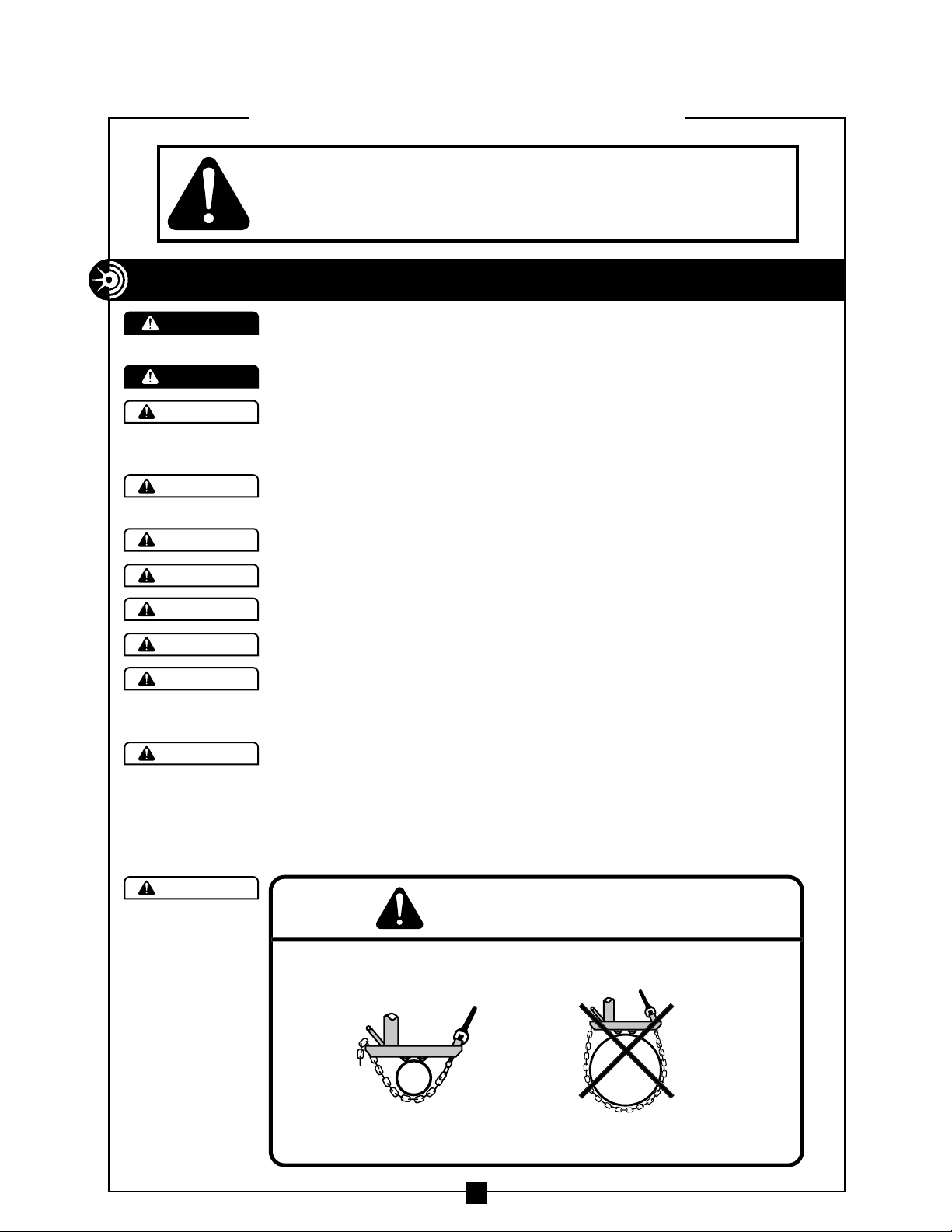
NEVER allow the rope to overlap on the capstan. If this condition
begins to occur, immediately release the tailing force on the rope
so that the rope can feed back toward the conduit or cable tray.
If this does not remedy the overlap, turn off the cable puller
immediately. There is
no known solution for
rope overlap.
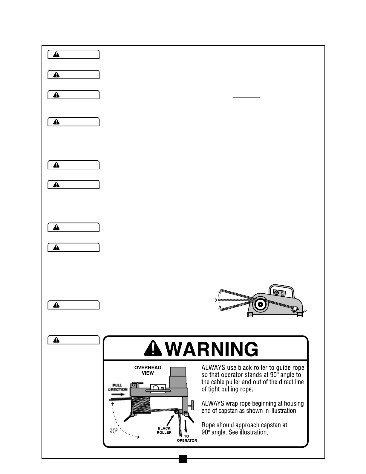
Rope should approach
capstan as shown in
Figure 1.