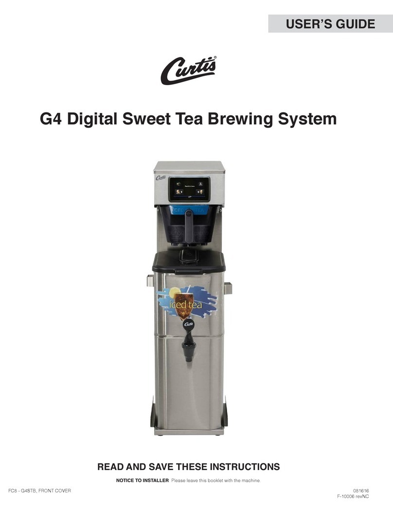
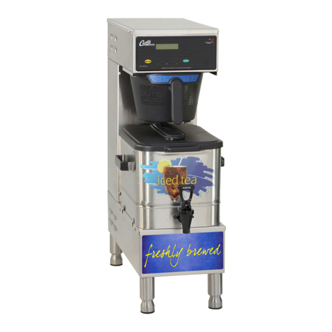
Curtis TCT-35 User manual

TCT-35 and TCT-35S
Iced Tea Brewers
Service Manual
12
12
12
12
12
Contents
Shipping List . . . . . . . . . .
SetupInstructions....
BrewingInstructions..
Filter Packs, Special
Instructions..........
Troubleshooting......
Cleaning . . . . . . . . . . . . .
Tea Tips . . . . . . . . . . . . . .
Wiring Diagram . . . . . . .
IllustratedParts.......
Parts List . . . . . . . . . . . . . .
1
1
2
2
3
4
5
5
6
7
Page
IncludedinthisservicemanualisinformationontheTCT-35andTCT-35S.
TheinformationiscommontobothTCTbrewersexceptwherenoted.
For 220 volt units, a separate wiring diagram and parts list will be
provided.
FOR THE LATEST SPECIFICATION INFORMATION GO TO WWW.WILBURCURTIS.COM
WILBUR CURTIS CO., INC.
6913 Acco St., Montebello, CA 90640-5403 USA
Phone: 800/421-6150 Fax: 323-837-2410
Web Site: www.wilburcurtis.com

SHIPPING LIST
1. Iced Tea Brewer
2. PB-2 Brew Basket
3. Brew Cone
4. Paper Filters
TCT-35 or -35S
WC-3322
WC-3320
GEM - 6
1
1
1
25
Item Part
Number Quantity
Supplied
1. Loosenthefourslotted screws and removethe
topcover.Removetheheatingtanklid.
2. Pour water into the heating tank until the water
level is one to two inches below the siphon
tube. Replace the tank lid.
3. Connectawater lineto theinletvalvebehind the
machine.Turnonwater.
4. Locate the thermostat. Turn the stem of the thermo-
stat clockwise until it stops.
5. Plug in the electrical cord to a 120 VAC, 20 Amp,
outlet. Flip the toggle switch, located behind the
machine, to the ON position. At this time the
READY TO BREW light will be off.
6. Wait about 20-25 minutes for the water to reach
brewingtemperature.
7. Because of the siphon system, proper water level in the heating tank must be established:
a. Place iced tea dispenser on the brewer, under the empty brew cone.
b. Press the brew switch.
c. As soon as you see water flowing, switch off the ON/RESET switch.
d. The water level in the heating tank is now correct and the machine is ready to brew.
e. Make sure the READY TO BREW light is on. This indicates the water in the heating tank is at
operatingtemperature.
8. Thedualtimeroperationandsetting:TheConcentrateKnobdeterminestheentire
length of brew cycle, while the Dilution Knob establishes the length of each of the
five (5) cold water cycles within the brew cycle in order to reach the correct hot to
coldwaterratio.
a. Theamount oftea concentratebrewed canbeadjusted bythe timer
knobmarked CONCENTRATE.Use one(1)gallon asthe standardsetting.
b. The ratio of tea concentrate to cold water can be adjusted by the
timerknobmarkedDILUTION.
c. Thestarting ratiowill beone gallonconcentrate andtwo gallons of
dillution.The ratio canbe adjustedto obtain the desired brew.
SET-UP INSTRUCTIONS
123
1
2
3
1
2
3
1
2
3
123
12
DUALINLETVALVE
HEATINGTANK
DUALBREW
TIMER
THERMOSTAT
ON/RESETSW.
BREW SW.
COMPONENTS, TOP VIEW
GAL
CONCENTRATE
.5
2
GAL
DILUTION
3
16
24
1
4
z
z
z
z
z
z
z
- 1 -
NOTE: These brewers are set at the factory to brew 3 gallons (TCT-35S) or 5 gallons (TCT-35).

F-1958. 8/2/96 P3
- 2 -
1
2
3
1. Once the water in the tank reaches
the proper temperature (200º F),
the READY TO BREW light will
come on.
2. Place filter into filter basket. Pour
leaf tea into basket. Slide brew cone
into brew rails.
3. With an iced tea dispenser in place,
push the brew switch.
Brewed tea will start to fill the tea
dispenser.
BREWING INSTRUCTIONS
SPECIAL INSTRUCTIONS FOR BREWING
WITH FILTER PACKS
SEPARATINGSPRAYHEAD
If you will be using tea that is packaged in a filter pack, it is recommended that the
waterspreaderportionofthetwo-pieceSprayheadberemoved.Thiswillallowfora
single stream of hot water to pour directly onto the tea package. The penetration of
water into the filter will help to increase the extraction from the tea package.
The threaded part of the Sprayhead is tightly fitted to the Spreader section. To
remove,grab the Spreader(withthe sprayheadstillon thebrewer)and pullit firmly
downward.Thetwopieceswillseparate, leavingthethreaded half stillonthe
machine.
Caution: Do not pull out brew cone until it stops dripping
to avoid scalding from hot liquid.

TCT-35, TROUBLESHOOTING
- 3 -
PROBLEM:Low temperature orcold waterin theheating tank.
POSSIBLECAUSE SOLUTION
Thermostatis
turnedoff Check to see that the thermostat is turned on. Twist the stem clockwise as far as it
will go.
PROBLEM:No responsewhen BrewSwitch isdepressed. Nohot or coldwater dispensed.
POSSIBLECAUSE SOLUTION
Waterlineturnedoff
orfilterclogged
Faulty Brew Switch
WC-122
FaultyBrewTimer
WC-655
Disconnectthewater linefromthe inletvalve andcheckthe waterpressure. Recon-
nectthe waterline.Replace thefilter cartridgeandremove anyobstruction. Note:
Theminimumpressureon theinlet valveshould be20 PSI.
While pressing the Brew Switch, check for continuity between the two side termi-
nals, 4B and 5B. If you do not read 110 - 120V from 5B to L2, the switch is defec-
tive.Replace theswitch.
a. With a voltmeter, check the incoming power across terminals L1 and L2
(you should read 110 - 120V). If correct, the timer is energized.
b. Check the voltage across terminals S/S and L2 while pushing the brew switch.
At this time the timer should be energizing the coils of the water inlet valves to
open them. You should read 110V to 120V between the terminals of each coil. If
thereis no voltage, replace thetimer.
PROBLEM: No hot water flowing from Sprayhead. Only cold water cycles.
POSSIBLECAUSE SOLUTION
Faulty Water Inlet
Valve Coil,WC-824
FaultyBrewTimer,
WC-655
Witha voltmeter,check for voltage to thevalve coilfor theHOT waterside. Ifthere is
powerto thecoil and nowater isflowing, thevalve mustbe replaced.
Witha voltmeter, checkthe voltageacross terminals L2 and HOTterminal (press
brew switch to test). If voltage is not present, timer is faulty.
Faulty Water Inlet
Valve, WC-824
FaultyBrewTimer,
WC-655
PROBLEM: No cold water is flowing from the outlet.
POSSIBLECAUSE SOLUTION
Witha voltmeter,checkfor voltagetothe valvecoilfor theCOLD water side.If there
is power to the coil and no water is flowing, the valve must be replaced.
Witha voltmeter, checkthe voltageacross terminals L2 and COLDterminal. If
voltage is not present, timer is faulty.
CONTINUED...PROBLEM: Waterin Tankdoesnot gethot.
POSSIBLECAUSE SOLUTION
Burnedoutheating
element Read the current with a clamp ammeter on one of the two 14 gauge wires connected
tothe element.Turnon themachine.The metershould readapproximately 16
amperes.Ifyou cannotgetan amperereading, useavoltmeter tocheckforvoltage
acrossthe heatingelement terminals.If there areapproximately 115volts, the
elementis burnedout.Replace elements.

- 4 -
Regular cleaning of the TCT-35 Iced Tea Brewer is essential in maintaining the best quality iced tea
flavor that the unit is capable of brewing.
1. Wipe any spills, dust or debris from the exterior surfaces with a damp cloth. The outside surfaces
of the TCT-35 should be cleaned with stainless steel polish only, to prevent scratches.
2. Clean the sprayhead and domed area around the sprayhead with a detergent solution and scrub
well to remove residue. Rinse with and clear water. Dry with clean cloth.
3. Remove the wire filter holder from the brew basket and wash both parts with a detergent solution
or put these parts through a dishwasher.
4. Wash the tea container and top cover with a detergent solution. Remove the faucet assembly.
Unscrew the handle assembly from the faucet and remove. Clean the faucet shank with a gage
glass brush (circular bristle) by pushing the brush through the shank. Using the same brush clean
the faucet body inlet and outlet. Clean the faucet cap and silicone seat cup.
5. After the cleaning, place the parts (sprayhead, brewcone and basket and faucet parts) into a sink
to be sanitized.
CAUTION - DO NOT USE UNDILUTED BLEACH OR CHLORINE.
Mix one of three sanitizing solutions before pouring over the parts
to be sanitized: Chlorine (50 ppm), Iodine (14 ppm), or Quaternary
Ammonium compound (100 ppm). This solution should be warm
(75º F.) Let the parts soak for at least one minute.
6. Thoroughly rinse parts with clear, hot water.
7. Air dry, all parts that were sanitized.
8. After cleaning, sanitizing and drying, assemble any partstaken
from the TCT-35 and tea container.
TCT-35, CLEANING
SPRING
HANDLE
SHANK
C' RING
SEATCUP
STEM
FAUCET
BODY
WINGNUT
zz
zz
z
zz
zz
z
zz
zz
z
zz
zz
z
zz
zz
z
zz
zz
z
zz
zz
z
zz
zz
z
TC FAUCET
NOTE: On these brewers, the Low Water Cutoff Thermostat, part no. WC-508R, serves to
automatically cut off the power to the heating element in case the water level drops too low. When
the water level is so low that the element is exposed, the very hot temperature will cause the reset
button, on the thermostat, to pop out; thus preventing the heating element from burning out.
When the low water condition has been corrected, push in the red button on the thermostat to reset.
You will know when it has reset by a distinct click.
TEA TIPS
1. Store tea bags in a dark, cool and dry place away from strong odors and moisture. Do not
refrigerate.
2. Never hold finished brewed tea for more than eight hours at room temperature. Discard all
unused brewed tea after eight hours.
DO NOT REFRIGERATE UNUSED TEA OVERNIGHT FOR LATER CONSUMPTION.
3. Brew only enough tea that you reasonably expect to sell within a few hours.
4. To protect tea flavor and to avoid bacterial contamination and growth, clean and sanitize tea
brewing, storage and dispensing equipment at least once a day.
5. For any method described, use a thermometer to make sure that brewing water in your
equipment meets the temperature specified.

- 5 -

TCT-35 &TCT-35S
- 6 -
A
12
12
12
123
123
123
123
123
123
2
1
3
4
5
6

28
29
30
31
32
33
36
37
38
39
40
41
42
43
44
45
46
47
48
50
51
52
53
54
55
1
2
3
4
5
6
7
8
9
10
11
12
13
14
15
15A
16
17
18
19
20
21
22
23
26
WC-3322
WC-3320
WC-3201
WC-4003
WC-3992
WC-3963
WC-3647
WC- 655
WC- 202
WC- 114R
WC- 122
WC-39119
WC-4213
WC-2906
WC-54001
WC-54002
WC-4502
WC-5310
WC-2965
WC-1411
WC- 895
WC-2977
WC-4436
WC- 517
WC-2401
BREWBASKET,WIRE
BREWCONE/HANDLEASSY
BREWCONEHANDLE
NUT, 10-32 RETAINER
LABEL,ICEDTEABREWCONE
STICKER,CAUTIONBREWCONE
STRAINER
TIMER,DUAL115V
BREWLIGHT,115V
SWITCH,ON/OFF115V
SWITCH,BREW115V
LABEL,SWITCHPANEL
LOCKNUT,BRASS5/8"
SPRAYHEAD,BLUE
COVER,FRONT, TCB-35S
COVER, FRONT, TCB-35
SCREW,8-32x 3/8" PANHEAD
TUBING,SILICONE5/16"
SPOUT,BYPASS
BUSHING,SNAP-IN5/8"
VALVE,INLETDUAL120V10W
FITTING,SPRAYHEAD45°
SCREW,4x3/8PHILPANHEAD
THERMOSTAT,CAPILLARYSPST
FITTING,1/4x1/8FLAREELBOW
WC-54006
WC-1200
WC-1408
WC- 102
WC-54047
WC-3685
WC-5851
WC-43062
WC-29010
WC-4320
WC-6210
WC-4373
WC-2970
WC- 904-04
WC-5409
WC-29009
WC-4306
WC-4243
WC-4212
WC-4381
WC- 522
WC-54048
WC-3502
WC-4394
WC-4506
COVER,TOPBREWER*
POWERCORD,125V,6'
CORDGRIP,7/8"
TOGGLESWITCH,125V,20A
HEATINGTANKW/FITTINGS
INSULATION,WRAP
LID, TANK
GASKET,TANKLID
FITTINGOVERFLOW,BARBED
O'RINGSEAL,1/2"
SHIELD,BUBBLE
O'RING,3/4"
FITTING,SIPHON TUBE
ELEMENT,HEATING1.6KW120V
CLIP,THERMOSTATBULB
FITTING, TANK INLET/DRAIN
WASHER,.875O.DX.562IDSILICONE
LOCKNUT,3/4"BRASS
JAMNUT,5/8"BRASS
SHOCKGUARD, RSTT'STAT
THERMOSTAT, HI LIMIT HEATER DPST
HEATINGTANKCOMPLETE
RUBBER FEET, 8-32 STUD
SHOCKGUARD,HEATELEMENT
SCREW,8-32x 5/8SSPAN HD
Thepart numbersmentioned inthissection arefor 120volt componentsonly.For 220volt part
numbers,seethe-30wiringdiagram.
PARTS LIST - TCT-35 & TCT-35S, ICED TEA BREWER
* PRE-'94PRODUCTIONHAD16¾"LONGTOPCOVER.
- 7 -
DESCRIPTION
PART
Nº
ITEM
Nº DESCRIPTION
PART
Nº
ITEM
Nº

- 8 -
THIS PAGE
INTENTIONALLY
LEFT BLANK

Printed in U.S.A. 8/06 F-1958 Rev A
ProductWarrantyInformation
TheWilburCurtisCompanycertifiesthatitsproductsarefreefromdefectsinmaterialandworkmanshipundernormaluse. Thefollowing
limitedwarrantiesandconditionsapply:
3Years,PartsandLabor,fromOriginal DateofPurchaseondigitalcontrolboards.
2Years,Parts,fromOriginalDateofPurchaseonallotherelectricalcomponents,fittingsandtubing.
1Year,Labor,fromOriginalDateofPurchaseonallelectricalcomponents,fittingsandtubing.
Additionally,theWilburCurtisCompanywarrantsitsGrindingBurrsforForty(40)monthsfromdateofpurchaseor40,000poundsofcoffee,
whichevercomes first. StainlessSteel componentsare warrantedfor two(2) yearsfrom dateof purchaseagainst leakingor pittingand
replacement parts are warranted for ninety (90) days from date of purchase or for the remainder of the limited warranty period of the
equipmentinwhichthecomponentisinstalled.
Allin-warranty servicecallsmust havepriorauthorization. ForAuthorization,call theTechnical SupportDepartmentat 1-800-995-0417.
EffectivedateofthispolicyisApril1,2003.
Additionalconditionsmayapply. Gotowww.wilburcurtis.comtoviewthefullproductwarrantyinformation.
CONDITIONS&EXCEPTIONS
Thewarrantycoversoriginalequipmentattimeofpurchaseonly.TheWilburCurtisCompany,Inc.,assumesnoresponsibilityforsubstitute
replacementpartsinstalledonCurtisequipmentthathavenotbeenpurchasedfromthe
WilburCurtisCompany,Inc. TheWilburCurtisCompanywillnotacceptanyresponsibilityifthefollowingconditionsarenotmet.Thewarranty
doesnotcoverandisvoidunderthefollowingcircumstances:
1) Improper operation of equipment: Theequipment mustbeused forits designedandintended purposeandfunction.
2) Improperinstallation of equipment: Thisequipmentmustbeinstalledbyaprofessionaltechnicianandmustcomplywithalllocal
electrical,mechanicalandplumbingcodes.
3) Impropervoltage: Equipmentmustbeinstalledatthevoltagestatedontheserialplatesuppliedwiththisequipment.
4) Improperwatersupply: Thisincludes,butisnotlimitedto,excessiveorlowwaterpressure,andinadequateorfluctuatingwaterflow
rate.
5) Adjustments and cleaning: Theresetting ofsafety thermostatsandcircuit breakers,programming andtemperatureadjustments
aretheresponsibilityoftheequipmentowner. Theownerisresponsibleforpropercleaningandregularmaintenanceofthisequipment.
6) Damagedintransit: Equipmentdamagedintransitistheresponsibilityofthefreightcompanyandaclaimshouldbemadewiththe
carrier.
7) Abuse or neglect (including failure to periodically clean or remove lime accumulations): Manufactureris not responsiblefor
variationinequipmentoperationduetoexcessivelimeorlocalwaterconditions. Theequipmentmustbemaintainedaccordingtothe
manufacturer’srecommendations.
8) Replacementof items subject to normal use and wear: Thisshallinclude,butisnotlimitedto,lightbulbs,sheardisks,“0”rings,
gaskets,siliconetube,canisterassemblies,whipperchambersandplates,mixingbowls,agitationassembliesandwhipperpropellers.
9) Repairsand/orReplacementsaresubjecttoourdecisionthattheworkmanshiporpartswerefaultyandthedefectsshowedupunder
normaluse. Alllaborshallbeperformedduringregularworkinghours.Overtimechargesaretheresponsibilityoftheowner. Charges
incurredbydelays,waitingtime,oroperatingrestrictionsthathindertheservicetechnician’sabilitytoperformserviceistheresponsibility
oftheowneroftheequipment. Thisincludesinstitutionalandcorrectionalfacilities. TheWilburCurtisCompanywillallowupto100miles,
roundtrip,perin-warrantyservicecall.
RETURNMERCHANDISEAUTHORIZATION: AllclaimsunderthiswarrantymustbesubmittedtotheWilburCurtisCompany
Technical SupportDepartmentprior toperformingany repairwork orreturnofthis equipmentto the factory. Allreturned equipment
mustberepackagedproperlyintheoriginalcarton.Nounitswillbeacceptediftheyaredamagedintransitduetoimproperpackaging.
NO UNITS OR PARTS WILL BEACCEPTED WITHOUT ARETURN MERCHANDISE AUTHORIZATION (RMA). RMA NUMBER
MUSTBE MARKED ON THE CARTONOR SHIPPING LABEL. Allin-warrantyservicecallsmustbeperformedbyanauthorized
serviceagent. CalltheWilburCurtisTechnicalSupportDepartmenttofindanagentnearyou.
WILBUR CURTIS CO., INC.
6913AccoSt.,Montebello,CA90640-5403USA
Phone:800/421-6150 Fax:323-837-2410
TechnicalSupportPhone:800/995-0417(M-F5:30A-4:00PPST) E-Mail:[email protected]
WebSite:www.wilburcurtis.com
This manual suits for next models
1
Table of contents
Other Curtis Kitchen Appliance manuals

Curtis
Curtis RTB User manual

Curtis
Curtis TCT User manual

Curtis
Curtis G4 Series User manual

Curtis
Curtis CFB3 User manual

Curtis
Curtis TB User manual

Curtis
Curtis ThermoPro G4 User manual

Curtis
Curtis G4RSTB User manual

Curtis
Curtis TLXA30 User manual

Curtis
Curtis TCTS/T User manual

Curtis
Curtis FRW080 Operation manual