Curtis ThermoPro G4 User manual

G4 Digital Sweet Tea Brewing System
86(5·6*8,'(
5($'$1'6$9(7+(6(,16758&7,216
127,&(72,167$//(5: Please leave this booklet with the machine.
FC8 - G4STB, FRONT COVER 081616
F-10006 revNC

CONTENTS CL8
.H\)HDWXUHV6SHFLÀFDWLRQV6\VWHP5HTXLUHPHQWV................................................................................................FS8
,PSRUWDQW6DIHJXDUGV............................................................................................................................................... IS2
,QVWDOODWLRQ,QVWUXFWLRQV*HQHUDO.............................................................................................................................. II2
,QVWDOODWLRQ,QVWUXFWLRQV/HYHOLQJ6ZHHWHQHU:DWHU6XSSO\(OHFWULFDO .................................................................. II8
2SHUDWLQJ,QVWUXFWLRQV%UHZLQJ..............................................................................................................................OI4
2SHUDWLQJ,QVWUXFWLRQV6ZHHWHQHU&RQQHFWLRQ5HSODFHPHQW ..............................................................................OI14
&OHDQLQJ,QVWUXFWLRQV%UHZHU .................................................................................................................................CI1
&OHDQLQJ,QVWUXFWLRQV6ZHHW7HD0L[LQJ6\VWHP ...................................................................................................CI8
&OHDQLQJ,QVWUXFWLRQV7HD'LVSHQVHU......................................................................................................................CI6
3URJUDPPLQJ*XLGH ............................................................................................................................................... 3*
5RXJK,Q'UDZLQJ................................................................................................................................................... 5'
,OOXVWUDWHG3DUWV5HFRPPHQGHG3DUWV0DLQ&KDVVLV............................................................................................. IP8
,OOXVWUDWHG3DUWV5HFRPPHQGHG3DUWV7DQN$VVHPEO\ ........................................................................................ IP21
(OHFWULFDO6FKHPDWLF ..............................................................................................................................................ES11
7URXEOHVKRRWLQJ*XLGH ............................................................................................................................................7*
7URXEOHVKRRWLQJ*XLGH ..........................................................................................................................................7*
(UURU&RGHV .............................................................................................................................................................EC1
3URGXFW:DUUDQW\....................................................................................................................................................3:
G4STB, CONTENTS LIST 081516NC
Contact Information
Wilbur Curtis Co., Inc.
6913 Acco Street | Montebello, CA 90640 US
Phone: 323-837-2300 | Toll Free: 800-421-6150
'PSUIFMBUFTUTQFDJmDBUJPOTBOEJOGPSNBUJPOHPUPXXXXJMCVSDVSUJTDPN
5PMM'SFF].POEBZ'SJEBZA.M.- 4:00 P.M.PT
Email: [email protected]
%VFUPDPOUJOVFEQSPEVDUJNQSPWFNFOUUIFQSPEVDUTJMMVTUSBUFEQIPUPHSBQIFEJOUIJTHVJEFNBZWBSZTMJHIUMZGSPNUIFBDUVBMQSPEVDU

KEY FEATURES/SPECIFICATIONS/SYSTEM REQUIREMENTS FS8
Key Features
• Generation Four (G4) Digital Control Module – Large, 4.3” touchscreen. Icon-driven interface streamlines
operation. It provides precise control of all critical brewing functions.
• G4 Enhanced Tea Flavor and Clarity – With digital accuracy, two separate precision valves provide
unsurpassed control over brewing and dilution cycle.
• On-Screen Instructions – Provides fast, intuitive training; reduces service calls.
• Program selectable for brewing regular or sweet tea.
• Equipped with integral electric sweetener pump.
• Built-in Self Diagnostic System – Includes real-time feedback of the brewing process and energy saving mode.
• Industry’s most effective mineral tolerant design.
• Encapsulated control boards – Protect against steam, water and impact.
6SHFLÀFDWLRQV
(OHFWULFDO6XSSO\5HTXLUHPHQWV
MODEL # DESCRIPTION PHASE VOLTS AMPS HEATING CONFIG WIRE WATTS HERTZ GAL/HR
G4STB Single, Iced Tea Brewing System 1 PH 120 V 13.8 A 1 X 1600 W 2W + G 1650 W 50/60 Hz 12.0
'LPHQVLRQV :DWHU6XSSO\5HTXLUHPHQWV
MODEL # HEIGHT WIDTH DEPTH SHIP WEIGHT SHIP CUBE WATER CONNECTOR WATER PRESSURE MIN. FLOW RATE
G4STB 34.29” 10.11” 22.82” 48.0 lbs 9.14 cu ft µÁDUH
20 - 90 psi 1.0 gpm
G4STB, KEY FEATURES/SPECS/SYSTEM REQUIREMENTS 082316NC
• Brew Temperature = 204°F
• Minimum Brew Temperature = 199°F
• Brew Volume = Large-Small
• Energy Save Mode = Off
Following are the factory default settings for the combination brewer:

IMPORTANT SAFEGUARDS IS2
Symbols
This is the safety alert symbol. It is used to alert you to potential physical injury hazards. Obey all safety
messages that follow this symbol to avoid possible injury or death.
DANGER - Indicates a hazardous situation which, if not avoided, will result in death or serious injury.
WARNING - Indicates a hazardous situation which, if not avoided, could result in death or serious injury.
CAUTION - Indicates a hazardous situation which, if not avoided, could result in minor or moderate injury.
NOTICE - Indicates a situation which, if not avoided, could result in property damage.
IMPORTANT - Provides information and tips for proper operation.
SANITATION REQUIREMENTS
Important Safeguards/Conventions
WARNING:
• Make sure that this brewer is installed and grounded according to the INSTALLATION INSTRUCTIONS
CZRVBMJmFEQFSTPOOFMCFGPSFBUUFNQUJOHUPVTFJU'BJMVSFUPGPMMPXUIF*/45"--"5*0/*/4536$5*0/4
could result in personal injury or void the warranty.
• This appliance is designed for commercial use. Any service other than cleaning and preventive
maintenance should be performed by an authorized Wilbur Curtis service technician.
• 5PSFEVDFUIFSJTLPGmSFPSFMFDUSJDTIPDL%0/05PQFOUIFTFSWJDFQBOFMT5IFSFBSFOPVTFS
serviceable parts inside.
• Keep hands, arms and other items away from hot surfaces of the brewer during operation.
• Clean the brewer completelyCFGPSFVTJOHJUGPSUIFmSTUUJNFBDDPSEJOHUPUIF$-&"/*/(
*/4536$5*0/4$MFBOJUBTJOTUSVDUFEJOUIF$-&"/*/(*/4536$5*0/4
• Use this appliance only for its intended use, brewing hot and/or cold beverages.
$0''&&5&"#3&8&34*.1035"/54"'&(6"3%44:.#0-4 /$

INSTALLATION INSTRUCTIONS II2
Installation Instructions
Installation Requirements
• A secure surface capable of supporting the weight of the brewer.
• For brewers without an attached cord set: Appropriately sized, UL listed, grounding type power cable to meet
UIFFMFDUSJDBMTQFDJmDBUJPOTGPSUIFCSFXFS*GZPVIBWFRVFTUJPOTBCPVUUIFDPSSFDUDBCMFTJ[FBOEMFOHUI
DPOTVMUBRVBMJmFEJOTUBMMFS*GUIFCSFXFSXJMMCFIBSEXJSFEUPBKVODUJPOCPYUIFQPXFSDBCMFNVTUCFMPOH
enoughTPUIBUUIFCSFXFSDBOCFNPWFEGPSDMFBOJOHVOEFSOFBUI
• "HSPVOEFEFMFDUSJDBMDPOOFDUJPOUPBOFMFDUSJDBMDJSDVJUUIBUNFFUTUIFFMFDUSJDBMTQFDJmDBUJPOTPGUIFCSFXFS
(see SPECIFICATIONS5IFDJSDVJUNVTUCFQSPUFDUFECZUIFBQQSPQSJBUFTJ[FEDJSDVJUCSFBLFS*GZPVBSFOPU
DFSUBJOUIBUUIFFYJTUJOHDJSDVJUNFFUTUIFSFRVJSFNFOUTGPSZPVSCSFXFSDPOTVMUBMJDFOTFEFMFDUSJDJBO
• 8BUFSmMUSBUJPOTZTUFN3FRVJSFEUPNBJOUBJOUSPVCMFGSFFPQFSBUJPO8JMCVS$VSUJT$P*ODSFDPNNFOETB
8JMCVS$VSUJTBQQSPWFEXBUFSmMUFS7JTJUwww.wilburcurtis.comUPTFFUIFGVMMMJOFPG8JMCVS$VSUJTBQQSPWFE
XBUFSmMUFST
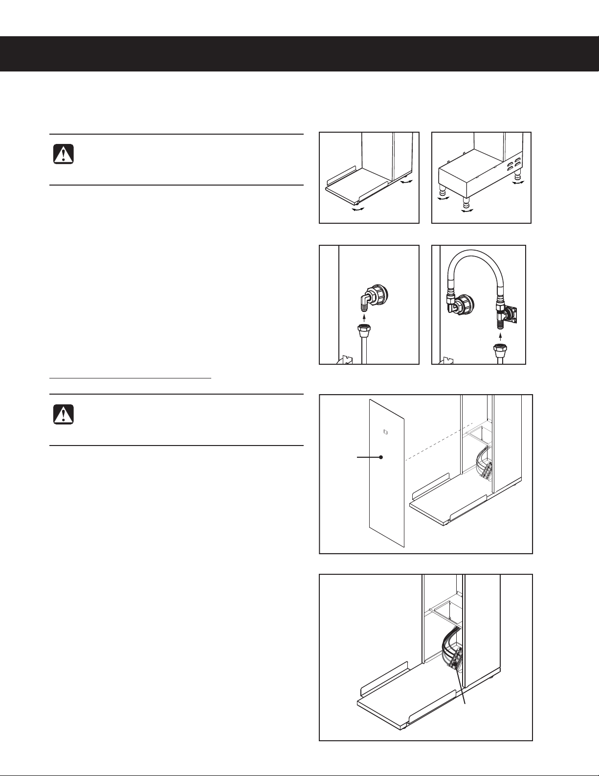
• 1PUBCMFXBUFSTVQQMZMJOFDPOOFDUJPOGSPNUIFXBUFSmMUFSDBQBCMFPGTVQQMZJOHUIFNJOJNVNnPXSBUFSFRVJSFE
CZUIFTQFDJmDBUJPOT5IFXBUFSTVQQMZMJOFNVTUCFBCMFUPDPOOFDUUPUIFnBSFmUUJOHPOUIFCBDLPGUIF
brewer. See the SPECIFICATIONS section for the correct size. The water line should also be capable of being
DPOUSPMMFECZBTIVUPGGWBMWF%POPUDPOOFDUUIFXBUFSMJOFUPBTBEEMFWBMWF
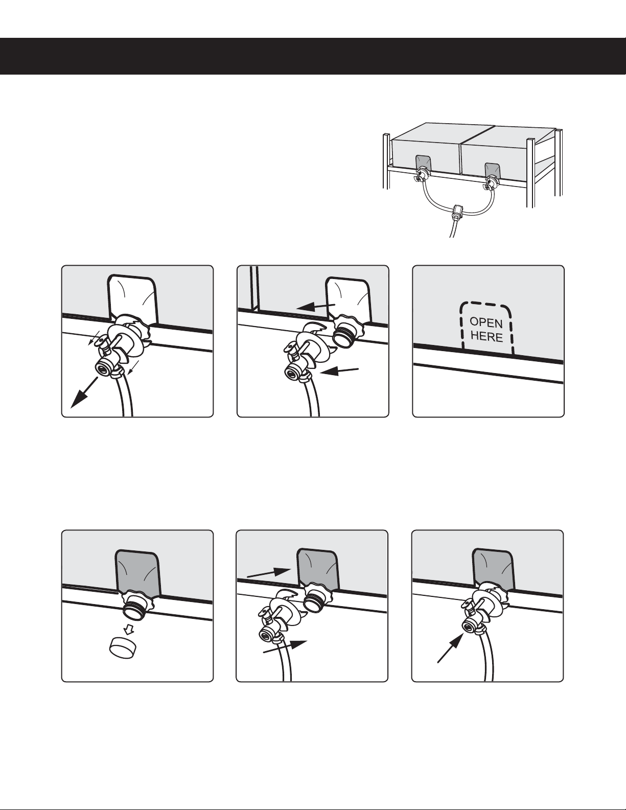
/4'*OUFSOBUJPOBMSFRVJSFTUIFGPMMPXJOHXBUFSDPOOFDUJPO
1 "RVJDLEJTDPOOFDUPSBEEJUJPOBMDPJMFEUVCJOHBUMFBTUUXPUJNFTUIFEFQUIPGUIFCSFXFSJTSFRVJSFE
TPUIBUJUDBOCFNPWFEGPSDMFBOJOHVOEFSOFBUI
2 5IJTFRVJQNFOUJTUPCFJOTUBMMFEXJUIBEFRVBUFCBDLnPXQSPUFDUJPOUPDPNQMZXJUIBQQMJDBCMF
federal, state and local codes.
8BUFSQJQFDPOOFDUJPOTBOEmYUVSFTEJSFDUMZDPOOFDUFEUPBQPUBCMFXBUFSTVQQMZTIBMMCFTJ[FE
installed and maintained in accordance with federal, state and local codes.
WARNING:*OTUBMMBUJPOJTUPCFQFSGPSNFEPOMZCZBRVBMJmFEJOTUBMMFS
WARNING: *NQSPQFS FMFDUSJDBM DPOOFDUJPO NBZ SFTVMU JO BO FMFDUSJD TIPDL IB[BSE 5IJT CSFXFS NVTU CF
properly grounded.
NOTICE:%0/05DPOOFDUUIJTCSFXFSUPBIPUXBUFSTVQQMZ5IFXBUFSJOMFUWBMWFJTOPUSBUFEGPSIPUXBUFS
%POPUFYDFFEUIFNBYJNVNXBUFSQSFTTVSFTUBUFEJOUIFSPECIFICATIONS section.
IMPORTANT:0CTFSWFBMMHPWFSOJOHDPEFTBOEPSEJOBODFT
#3&8&34(&/&3*$*/45"--"5*0/*/4536$5*0/4 /$
5IF*OUFSOBUJPOBM1MVNCJOH$PEFPGUIF*OUFSOBUJPOBM$PEF$PVODJMBOEUIF'PPEBOE%SVH"ENJOJTUSBUJPO
'%"'PPE$PEFNBOVBMEJSFDUUIBUUIJTFRVJQNFOUNVTUCFJOTUBMMFEXJUIBEFRVBUFCBDLnPXQSFWFOUJPO
in compliance with federal, state and local codes. For units installed outside of the U.S.A., make sure that
the installation is in compliance with the applicable plumbing/sanitation code for your area.

Installation
Leveling
1 Position the brewer on the counter top. Level it left to
right and front to back by turning the bottom of the
legs.
Connect the Water Supply
2 Flush the water supply line prior to installation to
QVSHFBJSBOEEFCSJTGSPNUIFXBUFSmMUFSBOEUVCJOH
3 $POOFDUUIFXBUFSTVQQMZMJOFUPUIFnBSFmUUJOHPO
the back of the brewer. Leave the water supply valve
closed until the power is connected.
Connect the Brewer Wiring
Brewers Without A Cord Set Attached
4 Remove the screws that hold the front cover in place
and remove the cover.
5 Loosen the strain relief on the back of the brewer.
6 On dual voltage units being operated at 220 Volts
(nominal) disconnect the existing power cable from
the terminal block and remove.
7 Feed the 220 Volt power cable into the brewer.
8 On dual voltage units being operated at 220 Volts,
disconnect and cap the jumper wire between the “C”
and “N” terminals on the terminal block.
9 Connect the wires on the power cable to the terminal
block inside the brewer.
10 Tighten the strain relief and replace the front cover.
11 Connect the power cable wires to the terminals in the
junction box. See the ELECTRICAL SCHEMATIC for
the power supply requirements.
INSTALLATION INSTRUCTIONS II8
DECANTER/DISPENSER BREWERS, INSTALLATION INSTRUCTIONS 080516NC
WARNING: Use the leveling legs to level the
brewer only. Do not use them to adjust brewer
height. Do not extend them higher than necessary.
Front
panel
WARNING: Turn off power to the junction box at
the circuit breaker panel before connecting the
power cable to the brewer.
Terminal
block

Brewers With A Cord Set Attached
12 Connect the power cord to the appropriate electrical
outlet.
Connect the Bag-in-Box (BIB) Sweetener -
Units Equipped for Brewing Sweet Tea Only
13 Connect two Bag-in-Box (BIB) sweeteners to the
brewer sweetener supply hoses as instructed in the
OPERATING INSTRUCTIONS section. Connecting two
bags allows the brewer to continue operating if one
bag runs out.
Power Up the Brewer
14 Turn on the water supply valve.
15 Make sure that the circuit breaker supplying power to
the unit is on.
16 Turn the toggle switch on the back of the brewer to the
0/QPTJUJPO5IFXBUFSUBOLXJMMTUBSUUPmMM8IJMFUIF
UBOLJTmMMJOHJOTQFDUUIFXBUFSTVQQMZMJOFGPSMFBLT
17 When the water in the tank rises to the correct level, the
heating elements will turn on automatically. Depending
on the incoming water temperature and the electrical
TQFDJmDBUJPOTUIFXBUFSUBOLUZQJDBMMZSFRVJSFTUP
minutes to reach the factory set operating temperature.
When the water has heated, Ready to brew will be
displayed on the LCD screen.
18 Perform a brew cycle of a least 12 ounces to purge
any remaining air from the system. See OPERATING
INSTRUCTIONS. During the initial brew cycle and
XIFOFWFSUIFmMUFSJTSFQMBDFEZPVNBZIFBSUIF
TPVOETPGBJSCFJOHQVSHFEGSPNUIFmMUFSUVCJOHBOE
water tank.
INSTALLATION INSTRUCTIONS II8
DECANTER/DISPENSER BREWERS, INSTALLATION INSTRUCTIONS 080516NC
Connect the Brewer Wiring (cont.)
WARNING: Connect the power cord to the
appropriate type and size electrical outlet. If the
electrical outlet is not compatible with the power
cord, have it upgraded by a licensed electrician. Do
not modify the power plug. Do not use an extension
cord. Do not use a power cord/plug that is damaged.
IMPORTANT: When operating the brewer at
higher elevations, reduce the operating
temperature by 2°F for each 1000 feet of
elevation. See PROGRAMMING GUIDE.

OPERATING INSTRUCTIONS OI4
Brewing Instructions
G4TB/G4STB, OPERATING INSTRUCTIONS 080416NC
2 Remove/open the lid from
an empty tea dispenser and
position it on the brew deck.
Center it under the brew
basket.
TEA
DISPENSER
3 *OTFSUBDMFBOQBQFSmMUFSJOUP
the brew basket. Fill with the
proper amount of leaf tea.
-FWFMUIFUFBJOUIFmMUFS
4 4MJEFUIFmMMFECSFXCBTLFU
into the brew rails under the
control panel. Slide it all the
way back until it stops.
5 )PMEZPVSmOHFSPOUIF
appropriate brew icon. As
soon as you hear the click
of the brew valve, lift your
mOHFS#SFXJOHXJMMCFHJO
5IFCSFXFSXJMMCSFXDPGGFFPSUFBCBTFEPOUIFTFUUJOHTQSPHSBNNFEJOUPUIFVOJWFSTBMDPOUSPMNPEVMF6$.5P
DIBOHFUIFTFUUJOHTTFFUIFPROGRAMMING GUIDE.
1 The brewer should be ON.
$POmSNUIJTBUUIFSFBSUPHHMF
switch. “Ready to brew”
should be on the display.
6 If a keypad appears on
the display, the brew code
GFBUVSFJTFOBCMFEEFGBVMU
JTPGGBrewing will start
immediately after you enter
the brew code. See the
PROGRAMMING GUIDE to set
up/disable the brew code.
WARNING - TO AVOID SCALDING, AVOID SPLASHING. ,FFQ CPEZ QBSUT DMFBS PG UIF CSFXFS EVSJOH
CSFXJOH%POPUSFNPWFUIFCSFXCBTLFUXIJMFi#SFXJOHwBQQFBSTPOUIFEJTQMBZ
WARNING - %0/05SFGSJHFSBUFVOVTFEUFBPWFSOJHIUGPSMBUFSDPOTVNQUJPO
The G4 Tea Brewer is factory preset for optimal performance.

OPERATING INSTRUCTIONS OI14
SWEETENER REPLACEMENT/CONNECTION, OPERATING INSTRUCTIONS 082216NC
Sweetener Bag-in-Box BIB Replacement/Connection Instructions
The sweet tea mixing system is designed to provide continuous
operation, provided that two BIBs are always connected. When one
BIB becomes empty, the system automatically switches over to the
other one. Replace empty BIBs immediately to assure continuous
operation.
2 Slide the QCD sideways off
of the BIB spout.
3 Place the new BIB container
on the rack and remove the
cardboard spout cover.
4 Pull off the shipping cap that
covers the spout on the bag.
5 Place the QCD next to the
spout, then slide sideways
until it stops.
The brewer will prime the new bag and begin to use the contents when the other bag runs out of sweetener.
1 Release the quick connect/
disconnect connector (QCD)
by pulling up on the hose
and cap assembly on the
opposite side. The plunger
will pop up in the center of
the QCD.
6 Push in on the QCD plunger
until it snaps into place.
Pull plunger out
before removal

NOTICE - Do not use cleaning liquids, compounds or powders containing chlorine (bleach) or corrosives.
5IFTFQSPEVDUTQSPNPUFDPSSPTJPOBOEXJMMEBNBHFUIFmOJTIFT USE OF THESE PRODUCTS WILL VOID
THE WARRANTY.
CLEANING INSTRUCTIONS CI1
Cleaning The Brewer - Daily
BREWERS - GENERIC, CLEANING INSTRUCTIONS 080416B
WARNING: HOT SURFACES - To avoid injury, allow the brewer and dispenser(s) to cool before cleaning.
The brewer should be OFF.5VSOUIFCSFXFSPGGCZnJQQJOHUIFSFBSUPHHMFTXJUDIUPUIF0''QPTJUJPO
1 Remove the dispenser(s). Wipe exterior brewer surfaces with a damp cloth to remove spills and debris.
2 Remove the brew basket(s) and clean them in a mild detergent solution. Use a soft bristled brush for hard to
clean areas. Rinse with clean water, then dry.
3 Wipe the spray head area with a cloth soaked in a mild detergent solution. Rinse with a cloth soaked with
clean water removing any residual detergent. Use a clean, soft cloth to dry.
4 Dump out the drip tray(s) (if applicable). Rinse with clean water, then dry with a soft, clean cloth.
Cleaning The Brewer - Weekly
The brewer should be OFF.5VSOUIFCSFXFSPGGCZnJQQJOHUIFSFBSUPHHMFTXJUDIUPUIF0''QPTJUJPO
1 Remove the spray head(s), unscrewing counterclockwise from the dome plate.
2 Thoroughly clean and rinse the dome plate area.
3 Clean the brew basket rails with a brush soaked with a mild detergent solution. Rinse the area with a cloth
soaked with clean water, removing any residual detergent.
4 Dry the area with a soft, clean cloth.
5 Reattach the spray head(s).
WARNING: DO NOT immerse the brewer in water or any other liquid.

CLEANING INSTRUCTIONS CI8
SWEET TEA MIXING SYSTEM - GENERIC, CLEANING INSTRUCTIONS 081516NC
Sweet Tea Mixing System Cleaning and Sanitizing (Weekly)
The brewer pours sweetener into the tea dispenser at the end of the brew cycle. Setting the brewer to Fast Brew
can speed up this cleaning procedure (see the PROGRAMMING GUIDE to turn on Fast Brew).
Use a concentrated cleaning solution to simplify the cleaning procedure. This procedure requires a one gallon
CVDLFUPGDMFBOJOHTPMVUJPOPGXBSNXBUFSBOEBHSBOVMBUFEDPODFOUSBUFETBOJUJ[FSDMFBOFSEJMVUFEBTTQFDJmFECZ
the manufacturer in a one gallon bucket of clean warm water (maximum 120ºF).
1 Make sure the brewer is on and the water supply
line is connected.
2 Remove both quick connect/disconnect (QCD)
connectors from the tea sweetener bag-in-box (BIB)
product bags.
3 Pull the caps off of the QCDs and immerse them in
the container containing the cleaning solution.
4 Place an empty container on the brew deck and
insert an empty brew basket into the rails below the
spray head.
5 Press the SWEET TEA brew button and run one
complete brew cycle.
6 Allow the brewer to sit for the amount of time
TQFDJmFECZUIFTBOJUJ[FSDMFBOFSNBOVGBDUVSFSXJUI
the cleaning solution in the sweetener hoses/lines
CFGPSFnVTIJOHUIFDMFBOJOHTPMVUJPO
7 'MVTIUIFTZTUFNCZmMMJOHBPOFHBMMPODPOUBJOFS
with clean warm water (no cleaning solution). Press
the SWEET TEA brew button to run a brew cycle
VOUJMBMMUIFDMFBOJOHTPMVUJPOIBTCFFOnVTIFEGSPN
the system.
8 Discard the solution that poured into the container
on the brew deck.
9 Remove the QCDs from the bucket containing the
hot water and replace the caps. Reconnect the
QCDs to the BIB product bags.
10 If Fast Brew option was selected for cleaning, reset
Fast Brew to OFF.
BREW
BASKET
BREW
BASKET
CLEANING - STEPS 1 TO 6
RINSING - STEPS 7 TO 10

CLEANING INSTRUCTIONS CI6
5&"%*41&/4&3$-&"/*/(*/4536$5*0/4ø /$
Cleaning the Tea Dispenser (Daily)
To clean, prepare a mild solution of detergent and warm
water. Remove the dispenser from the brewer and rinse.
Remove the lid from the dispenser. Wipe the exterior
surfaces with a sponge and the detergent solution to
remove spills and debris. Use the detergent solution and
a soft bristled brush to clean inside the container. Rinse
with clean, warm water and dry.
2 Sanitize the interior of the dispenser using a commercial
sanitizer suitable for food grade applications. Sanitize
according to the directions on the package.
3 Unscrew the faucet assembly from the dispenser. Then,
unscrew the handle/bonnet assembly from the top of
the faucet and remove. Inspect the seat cup for wear.
Replace the seat cup if it is damaged.
4 Clean the faucet parts with the detergent solution.
Thoroughly rinse all parts with hot water.
After cleaning, place the faucet parts in the sink to be
sanitized. Use a clean container to submerge all parts.
Immerse them in a commercial sanitizer suitable for food
grade applications. Sanitize according to the directions
on the package.
After cleaning, sanitizing and drying, reassemble the
handle/bonnet. Hand tighten the handle/bonnet onto the
top of the faucet assembly.
7 Hand-tighten the faucet assembly onto the dispenser
outlet.
Seat cup
Faucet
Handle
Bonnet

PROGRAMMING GUIDE PG1
Touchscreen Control Module
The touchscreen turns on whenever power is provided to the brewer and the rear toggle switch is on. The symbol
buttons on the screen control operation and programming. Pressing the on-screen symbols and buttons with
ZPVSmOHFSUJQBDUJWBUFTUIFWBSJPVTGVODUJPOT5IFEFGBVMUTDSFFOBTXFMMBTBEEJUJPOBMDPOUSPMCVUUPOTBSFTIPXO
CFMPX5IFDPOmHVSBUJPOPGUIFEFGBVMUTDSFFOWBSJFTEFQFOEJOHPOUIFCSFXFSNPEFM
2 The ACCESS CODE screen will appear. The
EFGBVMUQBTTDPEFJT0ODFUIFDPEFJT
FOUFSFEQSFTT0,5IF."*/.&/6TDSFFOXJMM
appear. The access code can be reset in the
$POUSPM4FUUJOHTTVCNFOVVOEFS1BTTXPSET
Status lights
Brew Buttons
Curtis logoHome Undo Scroll
left/right
Return to
previous
Control symbols - all
symbols may not be
present at the same
time
Entering Programming Mode
5BQUIFXIJUF$VSUJTMPHPPOUIFUPVDITDSFFOmWFUJNFTUPFOUFSQSPHSBNNJOHNPEFTFFEJBHSBNBCPWF
5IF."*/.&/6TDSFFODPOUBJOTBTFSJFTPGTVC
menu icons. The icons vary based on the model
TFMFDUFEVOEFSUIF.PEFM4FMFDUTVCNFOV'PS
UIFCSFXFSUPPQFSBUFQSPQFSMZUIFNPEFMTFMFDUFE
must match the model series on the brewer model
OVNCFSMBCFMBGmYFEUPUIFPVUTJEFPGUIFNBDIJOF
(130(3"..*/((6*%&ø #

PROGRAMMING GUIDE PG1
SELECTIONS FOR
COFFEE BREWER MODELS
SELECTIONS FOR
TEA BREWER MODELS
SELECTIONS FOR
COMBO BREWER
MODELS
Coffee
Gemini
Gemini IF
ThermoPro
Milano
Omega
Gourmet Std
Light Roast
Dark Roast
High Yield
Filter Pack
Decaf
Custom Recipe*
Model Select Control Settings Brew Settings
Recipes
Tea
Model Select Control Settings Brew Settings Settings Summary
Recipes
Combo
Model Select Control Settings Coffee
Brew Settings
Tea
Brew Settings Settings Summary Exit
Exit
Settings Summary Exit
Tea Recipes Coffee Recipes
Temperature
Warmer Settings*
Quality Timer
Energy Savings
Sounds
Diagnostics
Display Settings
Preventative Maintenance
Brew Counter
Passwords
Master Reset
Regional Settings
Filter Pre-Wet*
Custom Recipes
Chemex
V60
Kalita
Brew Basket
Custom Recipes
Thermo Pro 1G Single
Twin
Single
Twin
One Batch
Two Batch
Three Batch
One Batch
Two Batch
Three Batch
See Brew
Settings
One Batch
One Batch
Two Batch
Seraphim Single
Twin Paper Cup
Gold Cup
By Volume/Time
Pre/Pulse
Bypass
Drip Out
Flow Calibration
Tea/IC-1Batch
Tea/IC-2Batch
Tea/IC-3Batch
Tea/IC-4Batch
Tea-Sweet
Dual-Dilution
Dual-Sweet
Standard-Purple
Standard-Gray
Standard-Amber
Tropical-Purple
Tropical-Gray
76/308-Purple
76/308-Gray
Temperature
Quality Timer
Energy Savings
Sounds
Diagnostics
Display Settings
Preventative Maintenance
Brew Counter
Passwords
Master Reset
Regional Settings
Full Only
Full & Half
By Volume/Time
Dilution by Volume/Time
Dilution Delay/Stir/Fast-Brew
Pulses
Drip-Out
Sweetener*
Combo
Combo/IC
Combo-Sweet
Standard-Purple
Standard-Gray
Standard-Amber
Tropical-Purple
Tropical-Gray
76/308-Purple
76/308-Gray
Standard-Amber
Tropical-Amber
76/308-Amber
Standard-Purple
Standard-Amber
Gourmet Std
Light Roast
Dark Roast
High Yield
Filter Pack
Decaf
Temperature
Quality Timer
Energy Savings
Sounds
Diagnostics
Display Settings
Preventative Maintenance
Brew Counter
Passwords
Master Reset
Regional Settings
Full Only
Full & Half
Combo HV
Combo HV/IC
Single
Twin
By Volume/Time
Dilution by Volume/Time
Dilution Delay/Stir/Fast-Brew
Pulses
Drip-Out
Sweetener*
By Volume/Time
Pre/Pulse
Bypass*
Drip-Out
Pulses
Sprayhead Types
Flow Calibration
Batch Size
Sprayhead Types
Flow Calibration
Single*
Twin
Ceramic Cup
Paper Cup
Filter pack
One Batch
Two Batch
Three Batch
Programming
4IPXOCFMPXBSFUIFWBSJPVTQSPHSBNNJOHPQUJPOTBWBJMBCMFJOUIFQSPHSBNNJOH."*/.&/65IFJDPOTUIBU
BQQFBSWBSZCBTFEPOUIFCSFXFSNPEFMTFMFDUFEVOEFS.PEFM4FMFDU
'FBUVSFOPUBWBJMBCMFPOTPNFNPEFMT
(130(3"..*/((6*%&ø #

PROGRAMMING GUIDE PG1
USB - Easy Programming
5IFSFBSFUXPNFUIPETGPSDIBOHJOHUIFEFGBVMUTFUUJOHTPO(CSFXFST5IFTFUUJOHTDBO
CFQSPHSBNNFENBOVBMMZVTJOHUIFCSFXFSUPVDITDSFFOPSBVUPNBUJDBMMZVTJOHUIF64#
6OJWFSTBM4FSJBM#VTEBUBQPSUPOUIFTJEFPGUIFCSFXFS6TJOHUIF64#DPOOFDUJPOBOEB
nBTIESJWFFBTJMZSFQSPHSBNTUIFTFUUJOHTCZTJNQMZDPQZJOHEBUB
"nBTIESJWFDBODPQZBMMPGUIFTFUUJOHTGSPNPOFJEFOUJDBM(CSFXFSUPBOPUIFS%PJOHTPFMJNJOBUFTUIFOFFEUP
program each step individually using the touchscreen. This process also makes it easy to quickly standardize the
QSPHSBNTFUUJOHTPONVMUJQMF(CSFXFST
6TFBnBTIESJWFUIBUTVQQPSUT64#PSBCPWFBOEIBTBUZQF"64#DPOOFDUJPO5IFTUPSBHFDBQBDJUZNVTU
CF(#NJOJNVN
IMPORTANT:5IFnBTIESJWFNVTUCFcompletelyCMBOL&SBTFBOZFYJTUJOHmMFTPOUIFESJWFCFGPSF
TUBSUJOHUIFGPMMPXJOHQSPDFTT
Uploading the Software to the Flash Drive
.BLFTVSFUIFCSFXFSJTPO$IFDLUPNBLFTVSFUIBUUIFCSFXFSZPVBSFDPQZJOHTFUUJOHTGSPNJTQSPHSBNNFE
as desired.
2 0QFOUIFDPWFSPOUIF64#QPSUBOEJOTFSUUIFDPOOFDUPSPOUIFFNQUZnBTIESJWF5IFQPSUJTMPDBUFEPOUIF
SJHIUTJEFQBOFMPGUIFCSFXFSOFBSUIFUPQ5IFVOJWFSTBMDPOUSPMNPEVMF6$.XJMMVQMPBEBMMPGUIFTFUVQ
EBUBPOUPUIFnBTIESJWF5IFZFMMPX-&%JDPOPOUIFUPQMFGUPGUIFUPVDITDSFFOXJMMMJHIUJOEJDBUJOHUIBUEBUBJT
USBOTGFSSJOH5IJTQSPDFTTXJMMPOMZUBLFBTFDPOEUPDPNQMFUF
Downloading the Software to the Brewer from the Flash Drive
Select the (identical) brewer you wish to make program changes to. The brewer must be on.
2 1MVHUIFMPBEFEnBTIESJWFJOUPUIF64#QPSUPOUIFCSFXFS5IFEBUBDPQJFEGSPNUIFmSTUCSFXFSXJMM
BVUPNBUJDBMMZEPXOMPBEPWFSXSJUJOHBMMUIFTFUUJOHTUIBUXFSFPOUIFTFDPOECSFXFS
5IFSFE-&%POUIFUPQMFGUPGUIFUPVDITDSFFOXJMMJOEJDBUFUIBUUIFEPXOMPBEJTJOQSPDFTT5IJTXJMMPOMZUBLF
a second.
0ODFUIFEPXOMPBEJTDPNQMFUFUIF6$.XJMMSFCPPUTPUIBUUIFDIBOHFTUBLFFGGFDU
3FNPWFUIFnBTIESJWF5IFEPXOMPBEJTDPNQMFUF5IFEBUBPOUIFnBTIESJWFDBODPOUJOVFUPCFEPXOMPBEFE
into as many identical brewers as needed.
USB File Transfer
5IJTTDSFFOXJMMCFQSFTFOUXIFOFWFSUIF64#nBTIESJWFJTJOTFSUFE
provided the brewer is not currently brewing.
5IFEFGBVMUBDUJPOJTi/P"DUJPOw5IF6$.XJMMBMXBZTDSFBUFBCBDLVQ
POUIFnBTIESJWFCFGPSFEPXOMPBEJOHTFUUJOHTSFDJQFTPSBTDSFFOTBWFS
*GBmSNXBSFVQEBUFJTQSFTFOUPOUIFnBTIESJWFUIFmSNXBSFVQEBUF
QSPDFEVSFXJMMCFTUBSUFECFGPSFUIFTDSFFOJTTIPXO
FILE TRANSFER
Settings/recipes
Present on USB
Screensaver
Not present on USB
Start
Upload
to USB
Download
from USB No Action
(130(3"..*/((6*%&ø #

ROUGH-IN DRAWINGS RD9
10.04 in
[25.5 cm]
34.29 in
[87.1 cm]
9.11 in
[23.1 cm]
10.11 in
[25.7 cm]
0.49
[1.2 cm]
22.29 in
[56.6 cm]
22.67 in
[57.6 cm]
22.82 in
[58.0 cm]
16.61 in
[42.2 cm]
23.96 in
[60.9 cm]
13.41 in
[34.1 cm]
20.84 in
[52.9 cm]
1.29 in
[3.3 cm]
18.39 in
[46.7 cm]
12.06 in
[30.6 cm]
G4STB - Sweet Tea Brewer
G4STB, ROUGH-IN DRAWING 082316NC

ILLUSTRATED PARTS/RECOMMENDED PARTS IP8
G4STB, ILLUSTRATED PARTS/RECOMMENDED PARTS 090616NC
Supplies and Accessories - All Models
CAB-1 - Cleaning BrushWC-29025 - Spray Head
3
4
5
28
29
6
7
8
27
9
10
11
25
26
18
9
12
13
14
17
19
20
21
22
23
24
1
2
G4STB - Main Chassis - Exploded View
Sold by the case
16
15
SEE SECTION IP21
30

ILLUSTRATED PARTS/RECOMMENDED PARTS IP8
G4STB, ILLUSTRATED PARTS/RECOMMENDED PARTS 090616NC
ITEM # PART # DESCRIPTION
1 WC-58117 COVER, TOP ALPGT/D500GT/D60GT TLP/TCTS/
CBS/GEMSS
2 WC-589-101 TRANSFORMER,120VAC-24V 4.8A W/ LEADS &
MOLEX CONNECTOR
3 WC-13478 HARNESS ASSY COMPLETE G4TB
4 WC-43134 2·5,1*;2';:$//('307&76
5 WC-58017-104 COVER, FRONT TCTS
6 WC-66079 SPOUT ASSY , DILUTION PLASTIC
7 WC-10000 CONTROL MODULE, TOUCH SCREEN G4
8 WC-3398 BREW CONE, ASSY STD TEA NON METAL W/BLU
SPLASH POCKET
9 WC-8531 RAIL, BASE TCTD
10 WC-8556 HEATSINK, ASSY DV ALPDS/D500AP TCTD/PTTD
11 WC-10001 CONTROL MODULE, UPM 120/220V G4
12 WC-3503 LEG, 3/8”-16 STUD SCREW BUMPER
13 WC-5310 TUBE, 5/16 ID x 1/8W SILICONE GEN USE
14 WC-5231 COMPOUND, SILICONE 5 OZ
15 WC-889 9$/9('803/()79:$/3+$·6'
GEM-12/TLP
ITEM # PART # DESCRIPTION
10 WC-8556 HEATSINK, ASSY DV ALPDS/D500AP TCTD/PTTD
13 WC-5310 TUBE, 5/16 ID x 1/8W SILICONE
14 WC-5231 COMPOUND, SILICONE 5 OZ
15 WC-889 9$/9('803/()79:$/3+$·6'
GEM-12/TLP
G4STB - Recommended Parts to Stock
ITEM # PART # DESCRIPTION
16 WC-2977-101K KIT, SPRAYHEAD FITTING PLASTIC
17 WC-29044 SLEEVE, OVERFLOW ASSY GEN USE
18 WC-102 SWITCH, TOGGLE NON-LIT SPST 15A 125/6A
250VAC RESISTIVE
19 WC-10008 UNIVERSAL HOST ADAPTER USB
20 WC-37255 KIT, DUAL VALVE WATER INLET
21 WC-1200 &25'6-72·%/.:3/8*
22 WC-14045-101 CURRENT SENSOR ASSY G4
23 WC-1408 CORD GRIP, 7/8” O.D.
24 WC-29025 SPRAYHEAD, PURPLE ADVANCE FLOW
25 WC-895-105 VALVE, INLET DUAL 120V 10W 2 GPM X .5 GPM
26 WC-3518 LEG, GLIDE 3/8”-16 STUD SCREW
27 WC-37313 KIT, PUMP AND FITTINGS TCTS10200
28 WC-800 VALVE, TRANSFER FLOJET SWEET TEA
29 WC-8653 QCD, LIQUID BOX BAG CONNECTOR TCC1/TCC2
30 WC-43089 GASKET, 1.00OD X .625 I.D. X .030 THK WHITE
EPDM 70 SHORE
ITEM # PART # DESCRIPTION
16 WC-2977-101K KIT, SPRAYHEAD FITTING PLASTIC
18 WC-102 SWITCH, TOGGLE NON-LIT SPST 15A 125/6A 250VAC
RESISTIVE
20 WC-37255 KIT, DUAL VALVE WATER INLET
24 WC-29025 SPRAYHEAD, PURPLE ADVANCE FLOW
G4STB - Main Chassis - Parts List

ILLUSTRATED PARTS/RECOMMENDED PARTS IP21
WC-6277 TANK ASSEMBLY, ILLUSTRATED PARTS/RECOMMENDED PARTS 090616A
ITEM # PART # DESCRIPTION
1A WC-6277 TANK, COMPLETE 1600W 120V D500GT/TCTS/
PTT/CBS
1B WC-75236 TANK, ASSY D500GT/H/TCTS/PTT3/ CBS W/WC-
904 HEATING ELEMENT
2 WC-5853-102 COVER, TOP HEATING TANK GEN USE
3 WC-43062 GASKET, TANK LID
4 WC-5527K KIT, PROBE WATER LEVEL O-RING & NUT
5 WC-904-04 KIT,ELEMENT, HEATING 1.6KW120V W/ JAM NUT &
SILICONE O-RING
6 WC-1438-101 SENSOR, TEMPERATURE TANK
ITEM # PART # DESCRIPTION
3 WC-43062 GASKET, TANK LID
4 WC-5527K KIT, PROBE WATER LEVEL O-RING & NUT
5 WC-904-04 KIT,ELEMENT, HEATING 1.6KW120V W/ JAM NUT &
SILICONE O-RING
6 WC-1438-101 SENSOR, TEMPERATURE TANK
7 WC-4394 GUARD, SHOCK/HEATING ELEMENT FOR SINGLE
HEATING ELEMENT
WC-6277 - Recommended Parts to Stock
ITEM # PART # DESCRIPTION
8 WC-523 THERMOSTAT, MANUAL RESET 120/ 240 VAC 25A
220 DEG F MAX
9 WC-37365 KIT, FITTING TANK INLET
10 WC-37266 KIT, FITTING TANK OVERFLOW
11 WC-37317 KIT, STRAIGHT FITTING & BUSHNG 8mm GEN USE
ITEM # PART # DESCRIPTION
7 WC-4394 GUARD, SHOCK/HEATING ELEMENT FOR SINGLE
HEATING ELEMENT
8 WC-523 THERMOSTAT, MANUAL RESET 120/ 240 VAC 25A
220 DEG F MAX
9 WC-37365 KIT, FITTING TANK INLET
10 WC-37266 KIT, FITTING TANK OVERFLOW
11 WC-37317 KIT, STRAIGHT FITTING & BUSHNG 8mm GEN USE
12 WC-2630 BUSHING, CONICAL BLIND GEN USE
WC-6277 - Tank Assembly
2
3
10
12
11
7
6
8
9
1A
1B
5
4
WC-6277 - Tank Assembly - Parts List

ELECTRICAL SCHEMATICS ES11
G4 TEA BREWERS, ELECTRICAL SCHEMATIC 080416NC
112 Vac Input
212 Vac Input
3T ank Wat er Lev el Probe
4Vdd +5Vdc
5Not Used
6Tank Temperature Sensor
7Tank Temperature Sensor
8Data_Communication Next
(Not Used)
9Vss- (Logic_Common)
10 Not Used
11 Data_Communication First
12 Not Used
13 Not Used
14 UPM Ground
1TX - Transmit
2RX - Receive
3Not Used
4Vdd +5Vdc
5Vss- (Logic_Common)
rotcennoCniP41
rotcennoCniP5
1120V Hot Input
2120V Hot Input
3Brew Valve
4Not Used
5120V Neut ral
6Inlet Valve
7Not Used
8Not Used
9Triac Gate
10 Triac A2
11 Not Used
12 Not Used
13 Dilut ion Valve Right
14 Dilut ion Valve Left
15 Sweetner Pump
16 Sweetner Pump
17 120Vac Neutral (Internal Use Only)
18 Not Used
19 Current Sensor
20 Current Sensor
112 Vac Input (Back Light)
2Vdd +5Vdc
3Vss- (Logic_Common)
4Not Used
512 Vac Input (Back Light)
6Data_Communication First
7Not Used
8Not Used
1Vss- (Logic_Common)
2TX - Transmit
3Vdd +5Vdc
4RX - Receive
5Not Used
6Not Used
(UCM TOUCH SCREEN)
Pin Assignments
(USB) Pin Assignments
6-Pin Connector
(UPM) Pin Assignments
rotcennoCniP02
rotcennoCniP8
Model Voltage
V
Amps
A
WaƩs
W
Hertz
Hz
# of
Conductor
Wires
Phase # of Tank
Elements
Tank Element
RaƟng
W/V
G4TB
G4CB
G4RTB
G4RSTB
G4STB
G4TB2
G4CB2
G4RTB2
G4RSTB2
G4STB2
211
ELECTRICAL RATING TABLE
1600V/120V
1450V/120V
120
120
13.8 1650 2 1 150/60
50/6012.5 1500
G4 TEA BREWERS
Other manuals for ThermoPro G4
2
Table of contents
Other Curtis Kitchen Appliance manuals

Curtis
Curtis TCT-35 User manual

Curtis
Curtis G4RSTB User manual

Curtis
Curtis MILANO G3 User manual

Curtis
Curtis TCTS/T User manual

Curtis
Curtis TB User manual

Curtis
Curtis TLXA30 User manual

Curtis
Curtis G4 Series User manual

Curtis
Curtis TCT User manual

Curtis
Curtis CFB3 User manual

Curtis
Curtis Thermopro TLXA22 User manual