GENERAL INFORMATION BEFORE YOU START
HELPFUL HINTS:
A. Refer to parts diagram toward the back of this manual to help identify parts during the assembly process.
B. To assist with the cab installation, leave all bolts loose for later adjustment unless otherwise specified.
C. Read and understand all instructions before beginning.
D. Apply a silicone sealant to seal any minor gaps that may occur due to vehicle variations.
E. Use caution to avoid damaging the factory installed threaded inserts. Begin the bolt engagement by hand
to guard against potential cross threading.
F. Verify all hardware and cab parts are accounted for before beginning.
TOOLS REQUIRED:
Set of Standard Sockets (3/8” Drive)
One 3/8” Drive Ratchet
Long Socket Extension
Set of Standard Open End Wrenches
Set of Metric Open End Wrenches
Set of Standard Allen Wrenches
#2 and #3 Phillips Head Screwdrivers
Grease
Bar Clamp
CARE AND MAINTENANCE:
Check and tighten hardware after 40 hours of operation. Periodically inspect and tighten hardware for the remainder of the unit’s
life.
Wash with a mild soap or detergent using your bare hands to free or dislodge any caked-on dirt or other foreign particles.
Do Not use Windex or any other chemicals to clean plastic windows or vinyl components.
Be sure to regularly grease door hinge pins. Also lubricate moving parts in the door latches.
p. 2 of 13
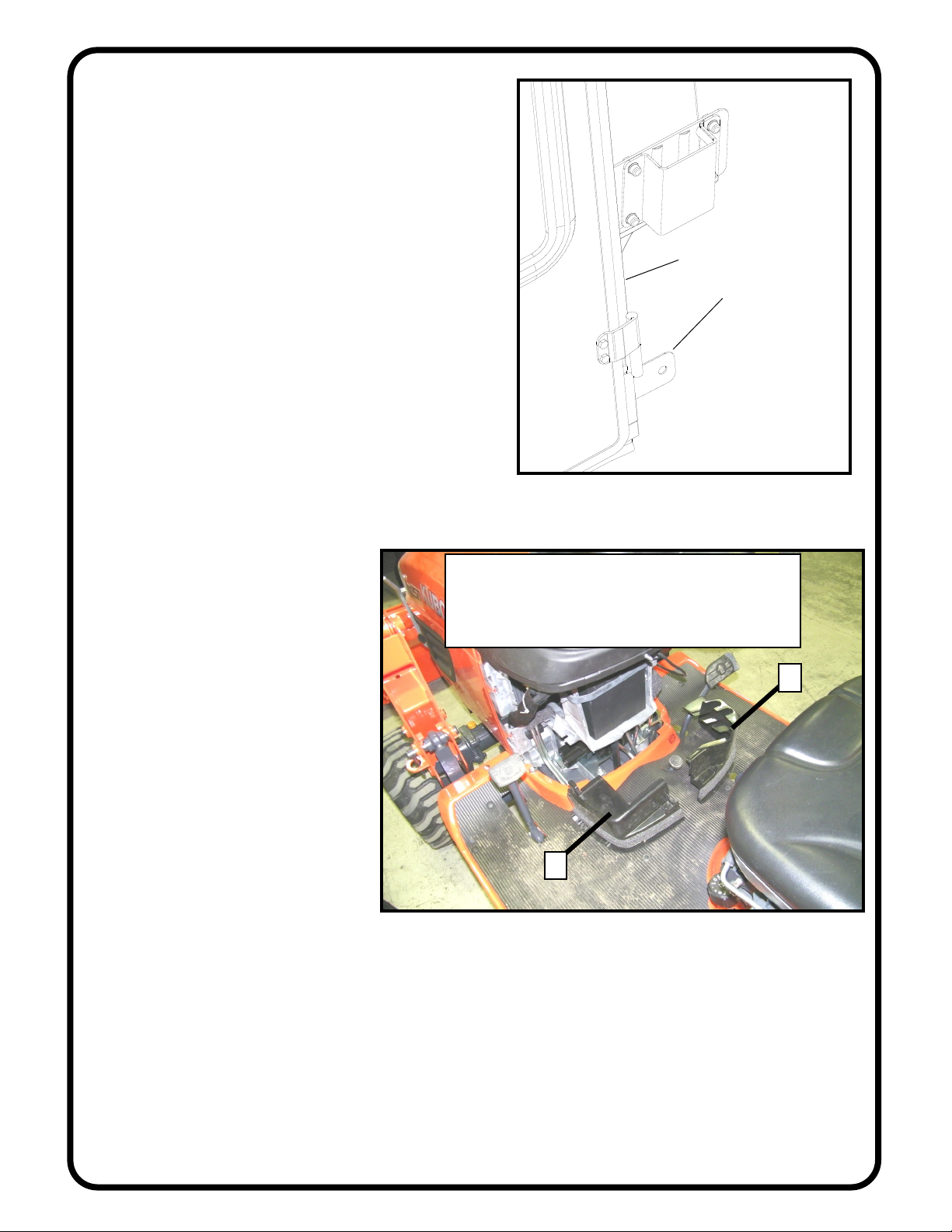
NOTICE
Cabs, blades, and general accessories add
additional weight to the base vehicle.
Deduct the accessory’s total weight from
the vehicle’s rated capacity including
driver and passenger.
Exposure to Carbon Monoxide
can Cause illness, serious injury
or death. Never operate vehicle if
suspicious of Carbon Monoxide. Inspect exhaust
system for leaks monthly. Leaks can result from
loose connections, corrosion, cracks or other dam-
age to the exhaust manifold. If leaks are found,
repair or replace exhaust system. Do not use vehicle
until repair or replacement is complete.