Curtis 1JDZ994RPR Operating instructions

1 of 34
INSTALLATION & OWNER’S MANUAL
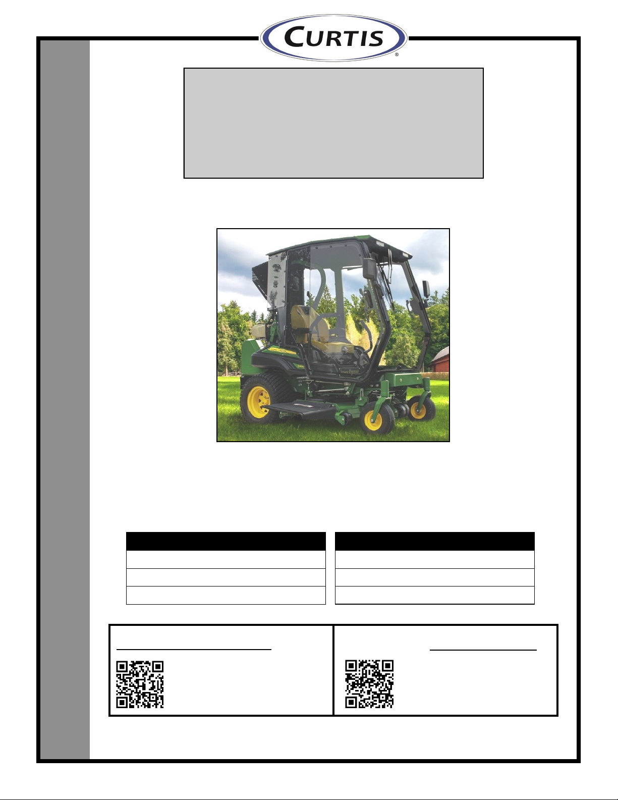
John Deere Z994R
(p/n: 1JDZ994RPR)
Cab with A/C
(fits both 60” and 72” mower decks.
Does not fit with mulching or 54” deck)
Requires Premium Seat
Rev. B, 10/25/2022
p/n: IM-1JDZ994RPR
(*=Not including accessories)
Approximate Installation Time *
Experienced Dealer Technician – 4 Hours
Average Dealer Technician – 6 Hours
Do-It-Yourself – 6-8 Hours
Approximate Product Specifications
Floorboard to Roof Height: 59 inches
Weight: 332 lbs.
Cab Width: 50 inches
The contents of this envelope are the property of the owner. Leave with the owner when installation is complete.
Register your new product quickly online at
Curtiscab.com/product-registration/
Download a digital copy of your installation
instructions online at Curtiscab.com/literature/
Curtis encourages all customers to register their
Curtis products. However, failure to do so will not
diminish right to warranty. Curtis Industries does not
sell or share your information with anyone else.
Curtis strives to continuously improve our products,
technical documentation, etc. Therefore, the
installation manual for this product may have been
updated after your product was packaged. The
latest revision of the installation manual can always
be found at the website above.
Premium Cab Shown with Options
Available Options:
1. Side View Mirrors (P/N: 9PM5)
2. Switch Panel (P/N: 1JDZ994RCK) (req’d for following 2 items)
3. Front LED Work Lights (P/N: 1ZTRLK)
4. Front Wiper/Washer Kit (P/N: 1ZTRWK)
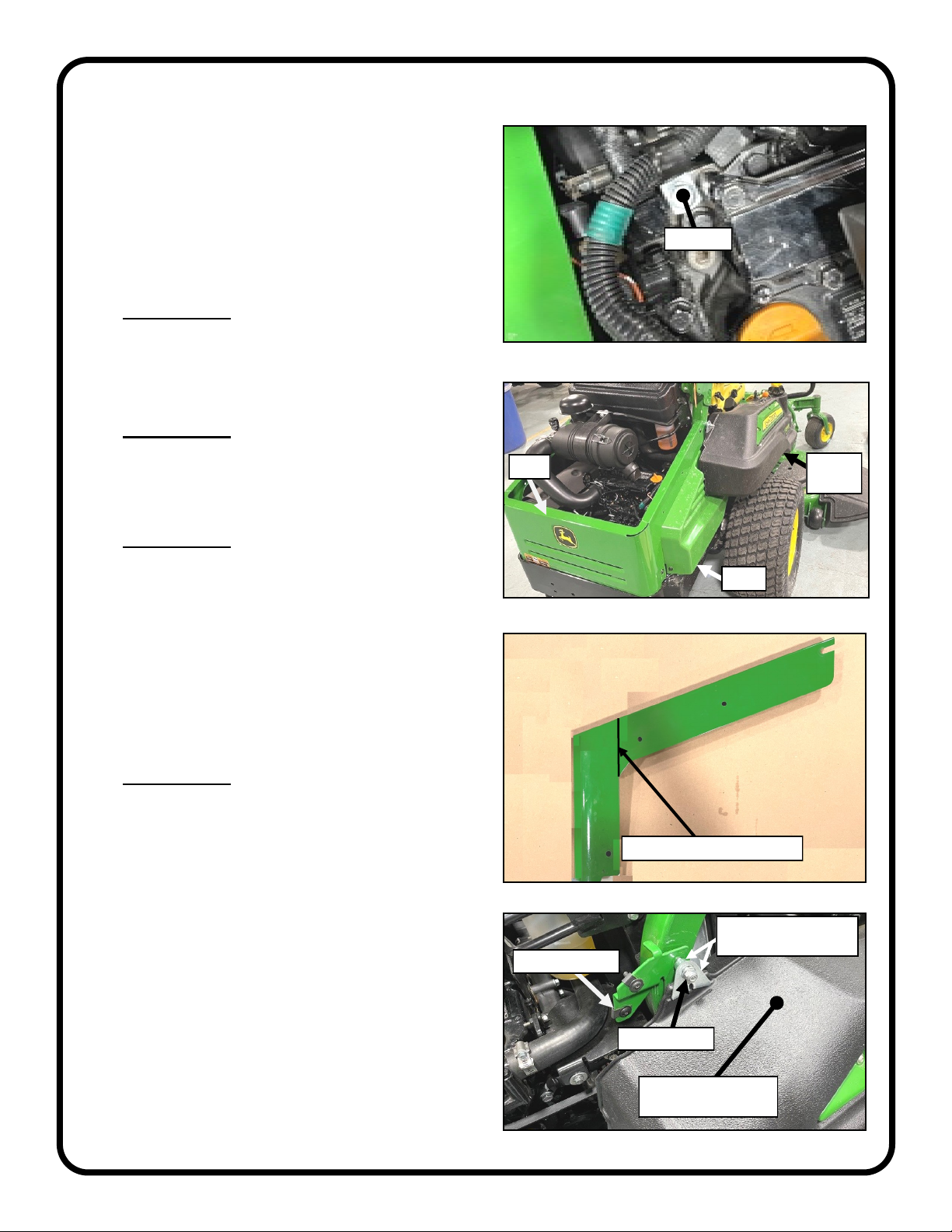
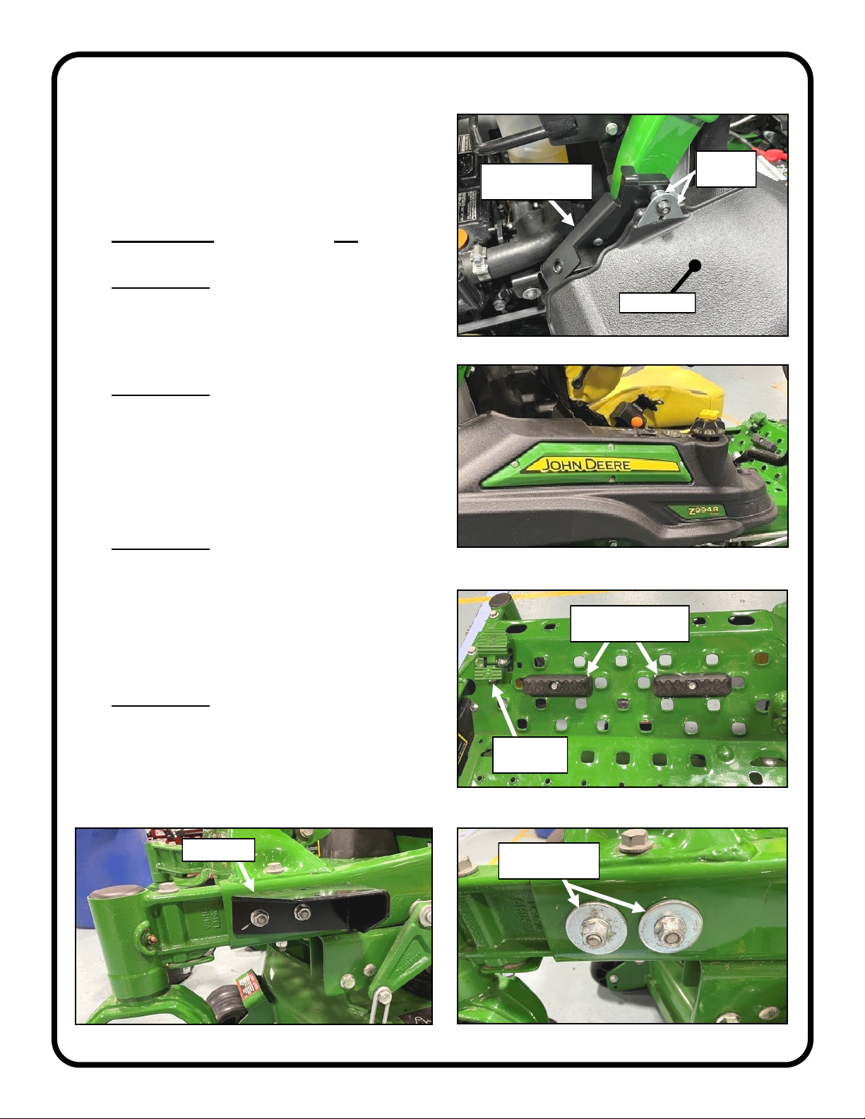
While this cab kit was designed to fit on the vehicle listed above, manufacturing tolerances and vehicle
assembly may affect cab fitment. It is the responsibility of the cab installer to check all vehicle pedals and
levers for full functionality and, as required, adjust the cab fitment to prevent any interference of the cab
components with the travel of pedals or levers.

2 of 34
TABLE OF CONTENTS
WARNINGS, TIPS, & REQUIRED TOOLS.......................................................3
VEHICLE PREP...........................................................................................4-12
CAB INSTALLATION .................................................................................13-24
CAB FEATURES & OPERATION ...................................................................24
CARE AND MAINTENANCE ..........................................................................25
TROUBLESHOOTING....................................................................................25
SERVICE PARTS .....................................................................................26-32
BOLT TORQUE SPECIFICATIONS ...........................................................33-34

3 of 34
Curtis cabs feature an assembly of parts designed for your vehicle which require adjustment
and alignment of components to accommodate vehicle variations and provide proper weather
protection. For accurate installation, proper operation, and years of satisfaction, please read
and understand the installation and owner’s manual fully prior to installing the cab.
From all of us at Curtis, we thank you for choosing our product.
HELPFUL HINTS:
•Refer to parts diagram found in the service parts section of this manual to help identify parts during the assembly process.
•To assist with the cab installation, leave all fasteners loose for later adjustment unless otherwise specified.
•Read and understand all instructions before beginning.
•Apply a silicone sealant to seal any minor gaps that may occur due to vehicle variations.
•Use caution to avoid damaging the factory installed threaded inserts or weld nuts. Begin the thread engagement by hand to
avoid or correct potential cross threading.
•Make sure the areas where the supplied self-adhesive hook Velcro will be applied are clean and dry and at room
temperature for best adhesion.
•Before installing parts with factory installed rubber, make sure the rubber is fully installed onto the parts for proper fit and
sealing.
driver and passenger.
Curtis accessory weights are listed in product
add additional weight to the base vehicle. All
Curtis Cabs, blades and general accessories
ADDED
WEIGHT
brochures. Deduct the accessory's total weight
from the vehicle's rated capacity and never
exceed the vehicle's rated capacity including
Exposure to Carbon Monoxide
can Cause illness, serious injury or
death. Never operate vehicle if suspicious of Carbon Monox-
ide. Inspect exhaust system for leaks monthly. Leaks can
result from loose connections, corrosion, cracks or other
damage to the exhaust manifold. If leaks are found, repair or
replace exhaust system. Do not use vehicle until repair or
replacement is complete.
•Set of Standard and Metric Sockets (3/8” + 1/2” Drive)
•T25 Torx Bit
•3/8” + 1/2” Drive Ratchets and Long Drive Extension
•Set of Standard and Metric Open-End Wrenches
•Set of Standard and Metric Allen Wrenches
•#1, #2, and #3 Phillips Head Screwdrivers
•Flat Head Screwdriver
•Grease Pencil or Marker
•Torque Wrench (3/8” and 1/2” Drive)
•Rubber Mallet or Plastic Dead Blow Hammer
•Bungee Cord or Twine
•Hoisting Strap
•Narrow Plastic Putty Knife
•Drill/Driver
•Center Punch
•9/32” Drill Bit
•#2 and #3 Phillips Head Bit
•Utility Knife
•Pair of Scissors
•Shears
•Grease
•Black Silicone Sealant
•Steel Straight Edge
•Belt tension gauge
•Angle Wire Cutters
WARNINGS, TIPS, & REQUIRED TOOLS
TOOLS REQUIRED:
GENERAL INFORMATION BEFORE YOU START
California Health and Safety Proposition 65 Warning: This product may contain chemi-
cals known to the state of California to cause cancer and birth defects or other reproductive harm.

CAB INSTALLATION
4 of 34
STEP 1: (VEHICLE PREP)
1.1 Park vehicle in a location accessible by an
overhead hoist.
1.2 Disconnect the negative battery terminal.
1.3 Remove screw and P-Clamp found on the engine
holding wire harness in place. See Fig. 1.3.
Tools required
13mm socket
1.4 Remove cover and grille from vehicle. Set aside
grille for later re-work and keep all removed
mounting hardware . See Fig. 1.4.
Tools required
T25 Torx Bit
1.5 Per Figure 1.5, cut off the right flange of grille at
marked edge. Apply touch-up paint to the cut
edges.
Tools required
Cut-Off Wheel or Jigsaw
1.6 Remove right fender.
Remove sleeve and retainer and set aside for later
re-installation. Remove bracket and M8X1.25
Lock Nut. See Figures 1.4 & 1.6
Remove Torx fasteners around instrument panel
Remove two fasteners securing the bottom of the
fender.
Tools required
T25 Torx Bit
10mm socket or wrench
13mm socket and wrench
Grille
Fig. 1.4 (Remove Cover and Grille)
Cover
Right
Fender
Fig. 1.6 (Remove Right Fender)
Remove Right Fender
+ Set Aside
Remove + Set Aside
Retainer & Sleeve
Remove Bracket
Remove Nut
Fig. 1.3 (Remove Screw and P-Clamp)
Remove
Fig. 1.5 (Cut Right Flange of Grille off)
Cut Grille Here

CAB INSTALLATION
5 of 34
STEP 1: (VEHICLE PREP CONT’D.)
1.7 Loosen alternator and remove OEM pulley and
spacer.
Install double V-Belt Pulley, per Fig 1.7. Re-
tension belt, apply finger pressure to the belt
approximately halfway between the alternator and
water pump pulleys. Belt should deflect between
3/8”-1/2". Adjust if too tight or too loose.
Tools required
24mm socket
13mm socket or wrench
15mm socket or wrench
1.8 Loosen the (2) hose clamps found on the hose
connecting the engine to the air cleaner. Next,
remove the air cleaner and (2) mounting screws/
nuts from the mounting bracket. Set aside hose, air
cleaner and hardware for later re-installation. See
Figure 1.8.
Assembly Tip: For easier removal of air cleaner
and later install, remove Cover found over the
radiator.
CAUTION!: DO NOT RUN THE VEHICLE UNTILL
STEP 2.38.
Tools required
13mm socket or wrench
5/16” socket or wrench
1.9 Remove cover from 2-pin connector found on right
side of vehicle. Next, cut wire tie and ensure
connector is accessible. See Figure 1.9.
Tools required
Angle Wire Cutters
1.10 Install spacer on outside of compressor mounting
bracket as shown on Fig 1.10. Use hardware
listed below.
Hardware Used Qty
1/4-20X1" Button Head Cap Screw 1
1/4-20 Flange Lock Nut 1
Tools required
5/32" Allen Wrench
7/16" Socket or Wrench
Air Cleaner
Hose
Bracket
Fig. 1.8 (Remove Hose and Air Cleaner)
Fig. 1.9 (Remove Cover from 2-Pin Connector)
2-Pin
Connector
Cover
Fig. 1.7 (Install Double V-Pulley)
Water Pump Pulley
Use
inside “V”
Apply Finger Pressure Here
Fig. 1.10 (Install Spacer to Bracket)
Bracket
Spacer
Nut
Button Head
Cap Screw
Wire Tie

CAB INSTALLATION
6 of 34
Fig. 1.13 (Remove Footrests & Brake Pedal Bolt)
STEP 1: (VEHICLE PREP CONT’D.)
1.11 Install Bracket and Spacer assembly from Step
1.10, on the outside of the right R.O.P.S. as well
as the sleeve and retainer with new M8X1.25 Nut
per fig 1.11. Leave hardware loose.
Hardware Used Qty
M8X1.25 Lock Nut 1
Tools required
13mm socket and wrench
1.12 Re-install right fender removed from step 1.4. At
this time, leave hardware installed on step 1.11
loose. See Figure 1.12.
Tools required
T25 Torx Bit
10mm socket or wrench
13mm socket and wrench
1.13 Remove and set aside footrests (this includes
bolts, fender washers, and nuts). Next, remove
M10 Carriage bolt and nut found below brake
pedal. See Fig. 1.13.
Tools required
13mm socket and wrench
15mm socket
1.14 Remove (2) M10 lock nuts and washers from the
left side of the vehicle’s caster arm per Fig. 1.14a.
Install front mount using the recently removed
M10 lock nut. Leave mounts loose per Fig. 1.14b.
Repeat on right side of vehicle.
Tools required
18mm wrench
19mm socket
Fig. 1.11 (Install Bracket & Spacer)
Curtis Bracket and
Spacer
Retainer
& Sleeve
Right Fender
Remove + Set Aside
Footrests
Remove Bolt
and Nut
Fig. 1.14a (Remove M12 Washers and Nuts)
Remove Washers
and Nuts
Fig. 1.14b (Install Front Mount, Left Side)
Front Mount
Fig. 1.12 (Re-Install Right Fender)

CAB INSTALLATION
7 of 34
Fig. 1.16a (Install Footrest Lip Floormat)
Ballast Box
Fig. 1.16b (Brake Pedal Hardware)Fig. 1.17 (Install Footrest Floormat)
Fig. 1.15a (Install Ballast Box, Backing Plate)
Fig. 1.15b (Install Ballast Box)
Top of Footrest Lip
Backing Plate
Install First
5/16” Hardware
Push Material Here
Clipped Washer
3/8” Washer
Cut out for
break pedal
Push Extra
Material to
Sides and Back
Rubber Surface
Requires Ratchet
Wrench
STEP 1: (VEHICLE PREP CONT’D.)
1.15 Remove ballast box from shipping pallet. Next,
install ballast box on the font edge, of the vehicle.
Installing top bolts first into the vehicles floorboard
(do not fully tighten). Place backing plate between
the underside of the floorboard and locking nuts.
Next, install front lower carriage bolts from inside
the vehicle floorboard outwards to the front of the
vehicle. To tighten down the lock nuts, you will
need a 3/4” rachet wrench to access the nuts
found on the inside of the ballast box. Fully
tighten the front bolts and then the top bolts. See
Figures 1.15a and 1.15b.
Hardware Used Qty
1/2-13X1-1/4” Carriage Bolt 4
1/2-13 Flange Lock Nut 4
Tools required
3/4" Ratchet Wrench
3/4" Socket or Wrench
1.16 Place the footrest lip floormat on the vehicle.
Place floormat material found on the lower right
and left into the sides of the vehicle frame. Install
5/16” hardware into square hole to the right of the
pedal. Next, install 3/8” hardware below the pedal
making sure 3/8”washers are wedged between the
vehicle and clipped washer. Re-install the vehicle
footrests. Now fully tighten hardware. See
Figures 1.16a and 1.16b.
Hardware Used Qty
3/8-16X1-1/2" Flange Hex Screw 1
3/8" Clipped Washer (in Hardware Box) 1
3/8" Washer 2
3/8-16 Flange Lock Nut 1
5/16-18X1" Flange Hex Screw 1
5/16" Fender Washer 1
5/16-18 Flange Lock Nut 1
Tools required
13mm socket and wrench
1/2" socket and wrench
9/16" socket and wrench
1.17 Install the footrest floormat making sure the rubber
is on the top surface (foam on bottom). Push the
extra material into the back edge and sides to fully
seal the floorboard. See Fig. 1.17.

CAB INSTALLATION
8 of 34
STEP 1: (VEHICLE PREP CONT’D.)
1.18 Tilt the seat forward.
1.19 Disconnect 2-pin connector from the underside of
the seat
Remove harness clip from the seat frame
Remove/set aside spring lock pin from prop rod.
While holding the seat, remove the prop rod from
the seat frame and set the seat back down. See
Figure 1.19.
Tools required
Needle Nose Pliers
1.20 Remove and save seat frame hinge bolts and nuts
per Fig. 1.20. Remove seat from vehicle.
Tools required
13mm socket and wrench
Fig. 1.19 (Disconnect Seat Connector & Prop Rod)
Disconnect
Seat Harness
Fig. 1.18 (Tilt Seat Forward)
Seat Latch Bar
Remove and Set Aside
Fig. 1.20 (Remove Front Hinge Bolts)
Prop Rod
Harness Clip
Spring
Locking Pin

CAB INSTALLATION
9 of 34
STEP 1: (VEHICLE PREP CONT’D.)
1.21 Apply 5/8” wide P.S.A. Velcro to the bottom edge
of Arm Restrictors. See Fig. 1.21.
Tools required
Scissors
1.22 Install the arm restrictors using 1/4-20 hardware,
making sure the locating pin is on the front hole as
shown in Figure 1.22.
Hardware Used Qty
1/4-20X3/4" Flange Hex Screw 2
1/4-20 Flange Lock Nut 2
Tools required
3/8" socket
7/16" wrench
1.23 Install (13) pieces of Velcro as shown in Figure
1.23.
Tools required
Scissors
Fig. 1.21 (Install Velcro to Arm Restrictors)
Apply Velcro
Fig. 1.22 (Install Arm Restrictors, Right)
1/4-20 Hardware Here
Fig. 1.23 (Install Velcro)
Place Velcro
Here
13 places
Pin

CAB INSTALLATION
10 of 34
STEP 1: (VEHICLE PREP CONT’D.)
1.24 Remove and set aside the (4) nuts and washers
holding the seat frame to the seat adjuster rails.
Next, remove frame from the seat. See Figure
1.24.
Tools required
13mm deep socket
1.25 Install (4) Clip-On Nuts using a socket to push
them onto the screws going through the (2)
adjuster rails. See Figure 1.25 with detail.
Hardware Used Qty
M8X1.25 Clip-On Nut 4
Tools required
7/16" deep socket
Socket wrench extension
1.26 Place supplied seat pan assembly onto seat.
Next, re-install seat frame onto the seat pan.
Loosely install OEM washers and nuts back on.
Fully tighten left side hardware first followed by the
right side. See Figures 1.24 and 1.26.
Tools required
13mm deep socket
1.27 Install supplied release lever by pushing through
the underside of seat pans rubber filler. Placing
the hole of the lever onto the seat frame’s latch
bar mounting bolt and the fork of the lever onto the
latch bar. Install lock nut onto the mounting bolt.
See Figures 1.26 and 1.27.
Hardware Used Qty
M10X1.5 Hex Lock Nut 1
Tools required
17mm wrench and socket
Fig. 1.26 (Install Seat Pan Assembly)
Fig. 1.25 (Install (4) Clip-On Nuts)
Fig. 1.24 (Remove Seat Frame)
Remove and Set Aside
Install Clip-Nuts Here
Fig. 1.28 (Install Release Lever)
Seat Frame
Front
Left
Seat Pan
Mounting Bolt
Latch Bar
Rubber
Filler
Release
Lever
Release
Lever Release
Lever’s Goes
Outwards

CAB INSTALLATION
11 of 34
STEP 1: (VEHICLE PREP CONT’D.)
1.28 Re-install seat with seat pan assembly back onto
the vehicle by re-installing OEM hinge bolts and
nuts per figure 1.28.
Tools required
13mm socket and wrench
1.29 Tilt the seat forward, while holding the seat, re-
install the prop rod to the seat frame and re-install
spring lock pin. Next, reconnect 2-pin connector
from the underside of the seat and re-install the
harness clip to the seat frame. Lower the seat
back down. See Figure 1.29.
Tools required
Needle Nose Pliers
1.30 Install left and right R.O.P.S. brackets onto the
vehicle’s R.O.P.S. See Figures 1.30a and 1.30b.
Hardware Used Qty
5/8-11X1-1/4” Hex Flange Bolt 4
5/8-11 Flange Hex Lock Nut 4
Tools required
15/16” wrench and socket
Fig. 1.30b (Install R.O.P.S bracket, right)
Fig. 1.29 (Reconnect Seat Connector & Prop Rod)
Fig. 1.28 (Re-Install Seat with Seat Pan)
Re-Install
Prop Rod
Harness Clip
Reconnect
Seat Harness
Fig. 1.30a (Install R.O.P.S bracket, left)
Spring
Locking Pin

CAB INSTALLATION
12 of 34
STEP 1: (VEHICLE PREP CONT’D.)
1.31 Remove compressor (with guard) and tensioner
from the compressor mount (keep 3/8” hardware
with compressor). Support the compressor using
a bungee cord or rope. Do not ever use the hoses
to support the compressor or damage may occur.
Next, remove compressor mount from rear
shipping bracket. See Figure 1.31.
Tools required
1/2” socket and wrench
9/16” socket or wrench
5/16” Allen wrench
1.32 Install compressor mount on the upper right side
of the engine. Use hex head screws and
washers** on top holes and flange hex head
screws on back side bolts. Torque screws to 19 ft-
lbs (26 N-M). See Figure 1.32.
**Note: washers are required on the top holes
so bolt do not bottom out in the engine.
Tip: Start bottom back side screw before
placing the compressor mount on the engine.
Hardware Used Qty
M8X1.25X25 flange hex screw 2
M8X1.25X40 hex screw 2
M8 washer 2
Tools required
13mm wrench and socket
1.33 Clean the vehicle frame rails on either side of the
floorboard. Apply P.S.A. D-Rubber (9PR09) to the
top surface of the frame rails. Apply along the
inner edge of the surface as shown in Figure
1.33.. Repeat for left side.
Tools required
Scissors
Fig. 1.31 (Remove Compressor Mount)
Tensioner
Compressor
Mount
Compressor
Guard
Fig. 1.32 (Install Compressor Mount onto Engine)
Hex Head Screws
+ Washer Here
Rear Shipping
Bracket
Fig. 1.33 (Install Rubber to Vehicle’s Frame, Right)
Apply Rubber
Here

CAB INSTALLATION
13 of 34
STEP 2: (CAB INSTALLATION)
2.1 Remove the doors from the cabin and set aside
carefully to prevent scratching the panels.
2.2 Lower the mower deck to 2”
2.3 Position a lifting strap so that it sits roughly 7-1/2”
behind the gas shock mount as shown in Figure
2.3.
2.4 Put tension on the lifting strap with the overhead
hoist. Remove and discard the (4) bolts holding
the rear of the cab down to the rear shipping
bracket (located inside the cab) as well as the (4)
bolts holding the floorboards to the front shipping
brackets. See Figures 2.4a, b, and c.
Tools required
1/2” wrench or socket
2.5 With assistance, lift the cabin and position over
the vehicle. Be sure to support the A/C
compressor so that it never hangs from the hoses.
2.6 Lower the cab slowly onto the vehicle being
careful to not scratch the fenders with the rear
edge of the floorboards.
Fig. 2.3 (Position Lifting Strap)
Fig. 2.4a (Tension Lifting Strap)
Overhead Hoist
Fig. 2.4b (Remove Front Shipping Bracket Bolts)
Fig. 2.4c (Remove Rear Shipping Bracket Bolts)
Remove
Remove

CAB INSTALLATION
14 of 34
STEP 2: (CAB INSTALLATION)
2.7 Install the back of the cab to R.O.P.S mounts per
Figure 2.7.
Hardware Used Qty
5/16-18X1-3/4” Flange Hex Screw 4
5/16-18 Flange Lock Nut 4
Tools required
1/2” wrench and socket
2.8 Install the front of the cab to front mounts per
Figure 2.8.
Hardware Used Qty
5/16-18X1” Flange Hex Screw 4
5/16-18 Flange Lock Nut 4
Tools required
1/2” wrench and socket
2.9 Fully tighten front mount hardware going into the
vehicle’s side frame. Torque to 110 ft-lbs. (150
Nm). See Figure 2.9.
Tools required
18mm wrench
18mm socket
Torque Wrench
2.10 Install one of the supplied brushes to the
underside of the right cab floorboard.
Next, install a second brush along with the
supplied floorboard insert on the inboard side of
the deck lift lever. See Figure 2.10.
Hardware Used Qty
#8-32 X5/8” Pan Head Screw 6
#8-32 Flange Lock Nut 6
Tools required
11/32” wrench or socket
#2 Phillips bit or screw driver
Fig. 2.7 (Install Back of Cab Screws)
Fig. 2.8 (Install Front Mount Screws)
Install
Fig. 2.9 (Tighten Vehicle Frame Bolts, Left)
Torque nuts to
110 ft-lbs. (150 Nm)
Fig. 2.10 (Install Brushes and Insert, Right)
Install
Right Brush
Insert
Left Brush

CAB INSTALLATION
15 of 34
STEP 2: (CAB INSTALLATION)
2.11 To install the compressor, run hoses from the left
to right side of the vehicle over the engine. Next,
re-install the compressor onto the compressor
mount. See Figures 2.11a and b.
Tools required
9/16” wrench or socket
5/16” allen wrench
2.12 Install V-Belt onto the outer “V” groove of the
double pulley found on the Compressor and install
the other end onto the double pulley found on the
alternator. See Figure 2.12.
2.13 Tension belt by placing a straight edge tangent to
compressor pulley and alternator. Place belt
tension tester in the center and perpendicular to
the belt between the (2) pulleys and next to the
straight edge. Push the tensioner towards the
theoretical center making sure that a deflection
force of 3.1 lbs. gets .2 inches of belt deflection at
the center of the belt. See Figures 2.12 and 2.13.
Tools required
9/16” wrench or socket
5/16” allen wrench
Belt tensioner tester
Straight edge
Fig. 2.11a (Install Compressor, Outside View)
Fig. 2.12 (Install V-Belt)
Fig. 2.11b (Install Compressor, Inside View)
Fig. 2.13 (Tension Compressor V-Belt)
Compressor Pulley
Alternator Pulley
Straight Edge
Belt Tension Tester
Set belt deflection distance to .2 inches
Set belt deflection force to 3.1 pounds
Center line
between pulleys
V-Belt
Use Outside “V”
of Double Pulley
Straight Edge
Tensioner

CAB INSTALLATION
16 of 34
STEP 2: (CAB INSTALLATION)
2.14 Slide the seat rearward then tilt seat forward.
2.15 Install right filler onto the cab from the outside
using provided hardware per Figure 2.15. Note:
side screws have lock nuts on the inside.
Hardware Used Qty
5/16-18X3/4” Flange Hex Screw 4
5/16-18 Flange Lock Nut 2
Tools required
1/2” wrench and socket
2.16 Install left filler onto the cab from the inside using
provided hardware per Figures 2.16a and b.
Hardware Used Qty
5/16-18X3/4” Flange Hex Screw 5
Tools required
1/2” wrench and socket
2.17 Apply P.S.A. Velcro on the left fender up the left
filler per Figure 2.17. Continue the Velcro on the
lower edge of the window.
Tools required
Scissors
Fig. 2.15 (Install Right Filler)
Into Inserts
Into Lock Nuts
Fig. 2.16a (Install Left Filler, Inside View)
Fig. 2.16b (Install Left Filler, Outside View)Fig. 2.17 (Apply Velcro to Left Filler and Fender)
Install
Install
Apply Velcro
Here

CAB INSTALLATION
17 of 34
STEP 2: (CAB INSTALLATION)
2.18 Place the rear panel assembly onto the R.O.P.S.
brackets apply pressure towards the AC Unit.
Install the top horizonal screws first and then the
(4) screws in two rear fillers. Attach to the
previously installed Velcro. See Figure 2.18.
Hardware Used Qty
1/4-20X5/8” Flange Hex Screw 4
1/4-20X3/4” Flange Hex Screw 2
1/4-20 Flange Lock Nut 6
Tools required
3/8” wrench or socket
7/16” wrench or socket
2.19 At the bottom of the left side rear panel assembly
there is a small piece of Velcro. Place a piece of
P.S.A. Velcro onto the rear fender as shown in
Figure 2.19. Attach lower corner of rear panel
vinyl onto installed Velcro.
Tools required
Scissors
2.20 Once the rear panel’s vinyl filler is fully installed
onto the mating Velcro, install hardware through
the Vinyl into the (2) fillers. See Figures 2.20a
and b. Do not over tighten or vinyl will be
damaged.
Hardware Used Qty
1/4-20X3/4” PH Truss Head Screw 2
1/4-20 Flange Lock Nut 2
Tools required
#3 Phillips Head Screwdriver
7/16” wrench or socket
Fig. 2.18 (Install Rear Panel Assembly)
Fig. 2.19 (Install Velcro, Left Fender)
Fig. 2.20a (Attach Rear Filler Vinyl to Left Filler)Fig. 2.20b (Attach Rear Filler Vinyl to Right Filler)
Install 1/4-20X3/4”
First
Install 5/8” lg.
last
Install Screw through
Vinyl and Rear Filler.
Phillips Head on
Inside of Cab.
Install Screw through
Vinyl and Rear Filler.
Phillips Head on
Inside of cab.
Apply
Velcro to
Left Fender

CAB INSTALLATION
18 of 34
STEP 2: (CAB INSTALLATION)
2.21 Slide the supplied right hand drive handle boot
down over the drive handles. (The right filler does
not have the hole shown in Figure 2.22)
Press the sewn on foam into the gap between the
frame and fender and attach the boot to the pre-
installed Velcro.
Move the drive handle forward and backwards as
well as left to right to determine best spot for
locating Velcro onto drive handles that will secure
the top edge of the boot and mark the top edge at
the appropriate location. See Figure 2.21.
Slide the boot down the handle and apply Velcro
around the handle below the mark.
Secure the top of the boot to the Velcro.
Tools required
Scissors
Marker
2.22 Repeat installation for the left boot.
Slide the hole in the left boot over the head of the
adjustment bolt as shown in Figure 2.22 upon
installation.
Tools required
Scissors
Marker
Fig. 2.21 (Loosely Install Drive Handle Filler, Right)
Fig. 2.22 (Install Left Filler, Outside)
Mark for Velcro
Bolt on Left
Side Only
Foam Goes
Here
Foam Goes
Here

CAB INSTALLATION
19 of 34
STEP 2: (CAB INSTALLATION)
2.23 Remove the (2) clips found on the sides of the air
cleaner mount and set aside. See Figure 2.23a.
Rotate both the elbow that houses the “Air
Restriction Indicator“ as well as the body of the air
cleaner in the mount roughly 180 deg until it looks
like Figure 2.23b.
Tools required
Flat Head Screw Driver
2.24 Per Figure 2.24, install relocation bracket making
sure fender washers are placed between
relocation bracket and vehicle’s bracket.
Hardware Used Qty
5/16-18X1” Flange Hex Screw 2
.349 X 1.129 Fender Washer 2
5/16-18 Flange Lock Nut 2
Tools required
1/2” wrench and socket
2.25 Re-install reconfigured air intake per Figure 2.25.
Make sure air intake is pointed vertically. At that
point, re-install clips into the air cleaner’s mount
removed on step 2.23. Fully tighten down hose
clamps found on the engine and air cleaner.
Make sure the extra part of the hose clamp
located on engine is pointing down away from the
fuel lines. If radiator cover was removed on step
1.8, re-install now.
Hardware Used
Use hardware set aside on step 1.8
Tools required
13mm wrench and socket
Fig. 2.23a (Reconfigure Air Cleaner, Stock)
Fig. 2.25 (Install Reconfigured Air Cleaner)
Remove +
Set Aside
Fig. 2.23b (Reconfigure Air Cleaner, New)
Fig. 2.24 (Install Relocation Bracket)
Relocation
Bracket
Bracket
Fender
Washer
Air Intake
Air Restriction
Indicator
Air Intake
Air Restriction
Indicator
Air Intake
Must Point
Vertically
Mount

CAB INSTALLATION
20 of 34
STEP 2: (CAB INSTALLATION)
2.26 Secure the larger AC hose and the wire harness
to the ROPS brackets using p-clamps as shown in
Figure 2.26.
Adjust hose and clamps so that the hoses are
away from the hot muffler when p-clamps are
tightened.
Hardware Used Qty
1/4-20X1” Button Head Screw 3
1/4-20 Flange Lock Nut 3
3/4” P-Clamp 3
11” Heavy Duty Wire Ties As Needed
Tools required
5/32” allen wrench
7/16” wrench or socket
Angle Wire Cutters
2.27 Run drain hose for AC Unit down in front of the
alternator and out the bottom of the vehicle. Keep
hose away from moving components and hot
engine parts. See Figures 2.27a, b, and c for
routing recommendations. Use provided Wire
Ties as needed.
Hardware Used Qty
11” Heavy Duty Wire Ties As Needed
Tools required
Angle Wire Cutters
Fig. 2.26 (Install Hose Clamps on R.O.P.S Brackets)
Fig. 2.27a (Routing Drain Hose)
Hose Clamps
Right Side R.O.P.S.
Run Drain Hose
Down Here
Compressor
Terminals
Fig. 2.27b (Drain Hose Between Radiator and R.O.P.S.)
Drain Hose
Fig. 2.27c (Drain Hose at Bottom of Vehicle)
Drain Hose
Table of contents
Other Curtis Safety Equipment manuals
Popular Safety Equipment manuals by other brands

Guardian Fall Protection
Guardian Fall Protection Diablo 2.0 Tie-Back SRL instruction manual

Respirex
Respirex WORKMASTER DIELECTRIC OVERBOOTS User information

Malta Dynamics
Malta Dynamics TR1000 instruction manual

Hubbell
Hubbell Chance Equi-Mat C6002850 instructions

IRUDEK
IRUDEK Hydro instruction manual

Singer Safety
Singer Safety 51SIREP15 (V2) quick start guide